User Manual Integrated Lithium-ion Battery - HUBBLE LITHIUM X100-48 - Full Circle Solar
←
→
Page content transcription
If your browser does not render page correctly, please read the page content below
HUBBLE LITHIUM X100-48

Integrated Lithium-ion Battery

User Manual

Version:V2.0
Released Date:2020-06-08
Quick Setup

The Hubble is designed to work with 48V UPS and inverter systems and will work under AGM charge
characteristics. For solar inverters that is not on the approved integration list it is recommended to set
your inverter battery parameters manually to ensure your battery operates at optimal levels.
It is highly recommended to study the manual before installation, however for quick setup and startup of
the Hubble Lithium pack, follow the following steps:
1. Ensure cuircuit breaker is in the OFF position
2. Securely connect the DC cables to the terminals ensuring correct polarity.
3. If the unit is in sleep mode (LED lights off), press and hold RESET button for 3 seconds. The LED's
will light up.
4. Switch on DC breaker.

Inverter setup for Axpert King & VMIII (with BMS port)
The Hubble has full integration with the Axpert King and VMII type inverters and other Axpert type
inverters with a BMS comms port.

To setup the Axpert King or VMIII, ensure you have at least firmware version 02.49 installed on the King
or VMII inverter. If you do not have this version please request it from your inverter supplier.

Connect the communications cable into port RS485-A and the other end into the Lithium RS485 port on
the inverter. Ensure you have the cable connected the correct way around as each side has a different pin
layout.

After the Lithium is connected and the inverter is powered on, change setting 5 in the inverter setup to
"Lib". This will enable the Lithium battery communication.

It takes up to 120 seconds to syncronize the communication. Once the battery icon on the inverter
flashes, communication has been successfully setup. No further settings or setup is required as the
battery will communicate to the inverter what charge, cutoff, float, bulk charge voltage should be used.

The below settings is for setting up Axpert type inverters that does not have the lithium comms port.

   Item                                                                         Settings Value

                                                               The Hubble is set to charge at a maximum rate of
                                                                                    21Amps.
Program 02              Maximum charge current                 Multiple batteries (2 or more) can be setup as as
                                                                     20Amps x (amount of Hubble units).

Program 05                    Battery Type                                            USE
Program 12             Voltage point back to Utility                                  48V
Program 13            Voltage point back to Battery                                   51V
Program 26             Bulk Charge Voltage (C.V.)                                    53.2V
Program 27                Float charge voltage                                       51.2V
Program 29               Low DC cut-off voltage                                       46V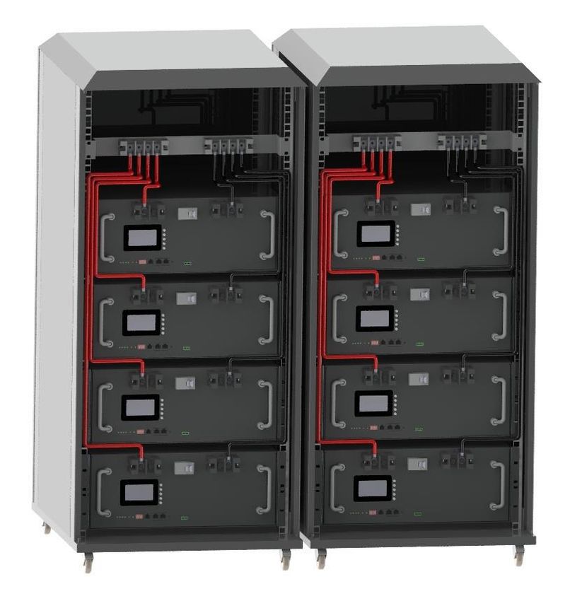
Integrated Lithium-ion Battery Pack For Solar &
UPS User Manual FOREWORD
FOREWORD
Overview
This manual describes the installation, history recording and parameter settings etc.
Readers
This document provides technical details regarding the tools and infrastructure used
by the following users:
Sales engineer
Technical support engineer
Installation engineer
Application engineer
Maintenance engineer
Symbol convention
The following symbols may appear in this article, and they are represented as follows:
Symbol Indication
Used as warning in an emergency, if not avoided, it will result in
death or serious personal injury.
Used as a warning of a middle or low potential hazards, if not
avoided, it may cause minor or normal injury.
All Right Reserved ©
ii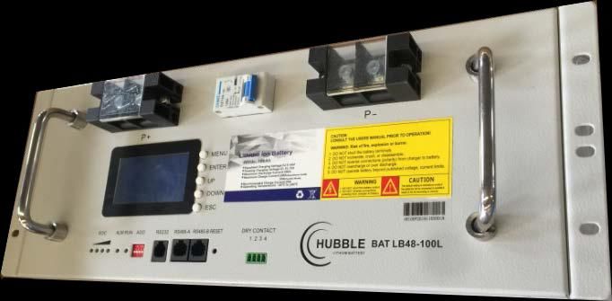
Integrated Lithium-ion Battery Pack For Solar &
UPS User Manual                                                                             FOREWORD

                                    Used as a warning of potential dangers, if ignore this information,
                                    it may result in equipment broken, data lost, equipment
                                    performance decrease and other unpredictable result.

                                    represents the supplement information of main text to emphasize
                                    or replenish.

                    All Right Reserved ©
                                                                                                      iii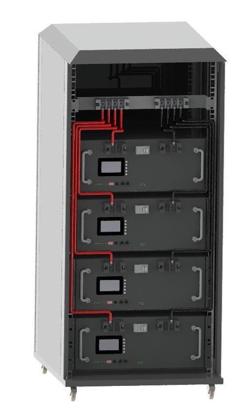
Integrated Lithium-ion Battery Pack For Solar &
 UPS User Manual                                                                                                                                        DIRECTORY

                                                                                                                                   DIRECTORY

FOREWORD..................................................................................................................................... ii

DIRECTORY..................................................................................................................................... iv

1 OVERVIEW..................................................................................................................................... 6
1.1 Product specification................................................................................................................................................ 6

1.2 Product profiles..........................................................................................................................................................6

1.3 Product structure.......................................................................................................................................................7

2 ILLUSTRATION............................................................................................................................. 8
2.1 Panel description....................................................................................................................................................... 8

2.2 Menu operation instructions................................................................................................................................13

2.3 The working principle.............................................................................................................................................14

2.4 The product features.............................................................................................................................................. 15

3 INSTALLATION GUIDE............................................................................................................. 17
3.1 Installation precaution notes................................................................................................................................17

3.2 Installation preparation..........................................................................................................................................19

3.2.1 Unpacking and inspection................................................................................................................................. 19

3.2.2 Installation tools................................................................................................................................................... 20

3.3 Installation and wiring............................................................................................................................................21

3.3.1 Standard cabinet installation.............................................................................................................................21

4 MAINTENANCE..........................................................................................................................27
4.1 Electrical maintenance............................................................................................................................................27

4.2 Battery maintenance...............................................................................................................................................28

4.3 Treatment for malfunctions...................................................................................................................................28

                                   All Right Reserved ©
                                                                                                                                                                        4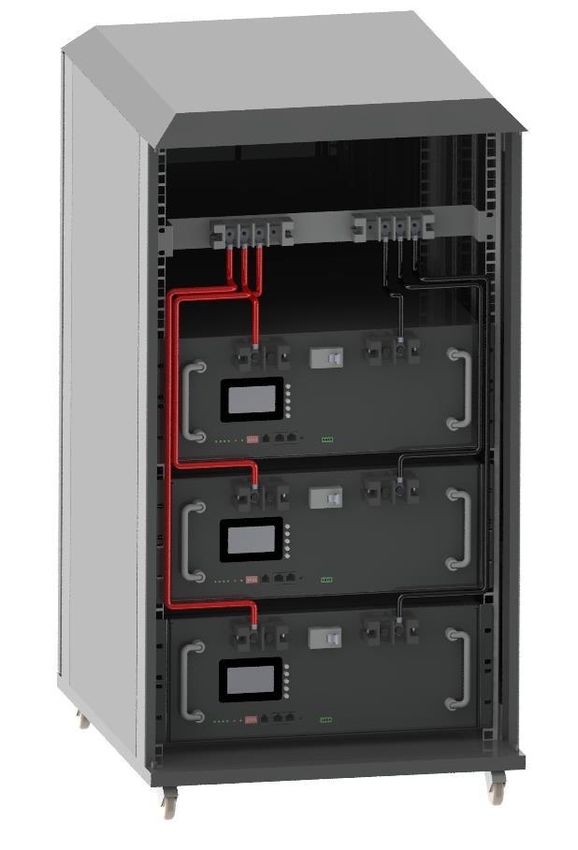
Integrated Lithium-ion Battery Pack For Solar &
  UPS User Manual                                                                                                                                            DIRECTORY

5 SPECIFICATIONS........................................................................................................................33
5.1 Technical specifications..........................................................................................................................................33

5.2 The main performance index of the battery....................................................................................................34

6 ENVIRONMENT PROTECTION..............................................................................................36
6.1 Environmental Label............................................................................................................................................... 36

6.2 Recycle........................................................................................................................................................................36

7 APPENDIX....................................................................................................................................37
7.1 Connection cable.....................................................................................................................................................37

8 G-SENSOR……………………………………………………………………………………………………………………………..39

                                    All Right Reserved ©
                                                                                                                                                                              5
Integrated Lithium-ion Battery Pack For Solar &
UPS User Manual                                                                             1 OVERVIEW

                                                                 1           OVERVIEW

1.1 Product specification
                  The model of integrated lithium Ion battery (hereafter referred to as lithium
                  battery or PACK) for Solar & UPS is the HUBBLE X-100.

1.2 Product profiles
                  The lithium battery group is developed by Supplier. Belonging to one of the series of
                  48V communication for back-up lithium battery products, the system adopts the
                  international advanced lithium iron phosphate battery application technology and
                  BMS control technology. Due to it’s a long lifecycle, small size, light weight, stable
                  performance, safety and environmental protection, as well as a strong ability to adapt,
                  it can be used in harsh outdoor environments.

                     All Right Reserved ©
                                                                                                     6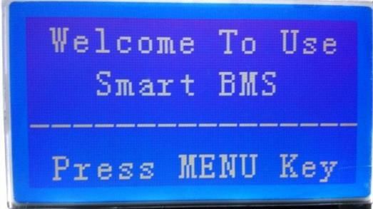
Integrated Lithium-ion Battery Pack For Solar &
UPS User Manual                                                                            1 OVERVIEW

                  The system integrates advanced battery manage system (BMS), including charge
                  and discharge management, thermal management, communication management,
                  balance management, data management, and realize remote centralized monitoring,
                  remote management and maintenance of the battery. It has outstanding advantages
                  in specific occasions, as a backup power supply is widely used in the remote access
                  network equipment, exchange, mobile communication equipment, transmission
                  equipment, satellite and microwave communication equipment and communication.

1.3 Product structure
                  The appearance of the lithium battery pack is shown in figure 1-2, for interface
                  description; please refer to the 2.2 panel description".

                  Figure1-2 Product picture

                     All Right Reserved ©
                                                                                                     7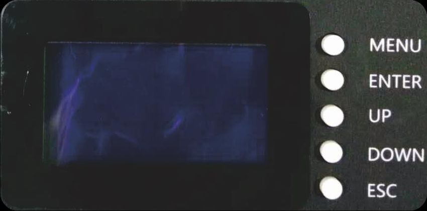
Integrated Lithium-ion Battery Pack For Solar &
UPS User Manual                                                                           2 ILLUSTRATION

                                                          2           ILLUSTRATION

2.1 Panel description
                  The lithium battery panel as the Figure2-1 shows below.

                  Figure2-1 Module panel description

               For detailed descriptions of each location, see the following figure2-2.

                     All Right Reserved ©
                                                                                                      8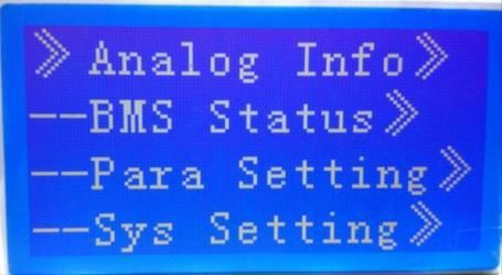
Integrated Lithium-ion Battery Pack For Solar &
UPS User Manual                                                                      2 ILLUSTRATION

                  Figure2-2 Panel Effect Chart

                   1 Handle           2 SOC (capacity light)   3 ALM(alarm)        4 RUN

                   5 ADD              6 RS232                  7 RS485             8 RESET / POWER ON

                   9 Dry Contact      10 Main panel            11 Mounting holes   12 Output-

                   13 MCB             14 Output﹢               15 LCD display

Handle
                  Made of galvanized steel and make it for transportation.

SOC
                  The meaning of SOC indication light shown in table 2-1

                  Table2-1 The relationship between the capacity of the battery and the light

                   ●                 ●                ●                ●              Capacity

                   ¤                 ¤                ¤                ¤              75%-100%
                   ¤                 ¤                ¤                ○              50%-75%

                   ¤                 ¤                ○                ○              25%-50%

                   ¤                 ○                ○                ○              0%-25%

                             ¤indicates ON,○indicates OFF。

                       All Right Reserved ©
                                                                                                 9
Integrated Lithium-ion Battery Pack For Solar &
UPS User Manual 2 ILLUSTRATION
ALM
When the battery is at fault, "ALM" light is red.
RUN
During charging, the "RUN" light will be flashing.
"RUN" and "ALM" can display the battery status, as shown in table 2-2.
Table2-2 The explanation of “RUN” and “ALM”
Function Mark Color Flashing frequency Indication
Running RUN Green No light Not working
Slow Flash(about 3 secs) Standby state
Fast flash Working state
Alarm ALM Red No light Normal
stable lighting Alarm
ADD
In parallel, band switch using four dip switch to address set cell system. The
explanation of its dial switch as shown in table 2-3.
Table2-3 Band switch address code
Address Code ADD PACK Explanation
Definition
1 2 3 4 5 6
OFF OFF OFF OFF / / 0 Use Alone
ON OFF OFF OFF 1 PACK Use As
MasterPack, Can
apply RS-232
OFF ON OFF OFF 2 PACK1 Use as SlavePack1
ON ON OFF OFF 3 PACK2 Use as SlavePack2
OFF OFF ON OFF 4 PACK3 Use as SlavePack3
ON OFF ON OFF 5 PACK4 Use as SlavePack4
OFF ON ON OFF 6 PACK5 Use as SlavePack5
ON ON ON OFF 7 PACK6 Use as SlavePack6
OFF OFF OFF ON 8 PACK7 Use as SlavePack7
All Right Reserved ©
10Integrated Lithium-ion Battery Pack For Solar &
UPS User Manual 2 ILLUSTRATION
Address Code ADD PACK Explanation
Definition
1 2 3 4 5 6
ON OFF OFF ON 9 PACK8 Use as SlavePack8
OFF ON OFF ON 10 PACK9 Use as SlavePack9
ON ON OFF ON 11 PACK10 Use as SlavePack10
OFF OFF ON ON 12 PACK11 Use as SlavePack11
ON OFF ON ON 13 PACK12 Use as SlavePack12
OFF ON ON ON 14 PACK13 Use as SlavePack13
ON ON ON ON 15 PACK14 Use as SlavePack14
1) Address code 5 and 6 are reserved and do not play any role.
RS232
The system uses RS-232 series load data for Solar & UPS, transfering data
including: system parameters, system status and alarm information.
Telecom RS-232 generally uses 1200bps. Connected with a high-end computer,
only when the dip switch is set to Pack (Master Pack) mode, the RS-232 comms
module is effective. Connection as shown in figure 2-3.
Figure2-3 RS-232 connection schematic diagram
RS485
All Right Reserved ©
11Integrated Lithium-ion Battery Pack For Solar &
UPS User Manual 2 ILLUSTRATION
When the system is in parallel mode, it can use the RS-485 serial comms for data
transfer. The main system through the Master Pack to get the data for each Slave
Pack. Connection as shown in figure 2-4.
Figure2-4 RS-485 connection schematic diagram
RESET / POWER ON
- Press RESET key for 3 seconds, the lithium pack will wake up from deep sleep.
- Press the RESET key for 3 seconds again, and the pack will shut down.
- When the system is running, should there be a error, press this button for 6
seconds to reset the system (press / release) to ensure the stability of the system.
Dry contact
The function of the dry node is to provide an interface for the status of the remote
monitoring battery. Failure Alarm: indicate BMS or battery fail including but not limited
to charge and discharge MOS fail, cell voltage under 0.5V, NTC disconnect.
Protection Alarm: Output short circuit, charge and discharge over current, charge and
discharge over temperature/low temperature.
Output
A total of 4 output terminals, 2 red positive, 2 black for the negative, each terminal is
the specification for M8 Stud.
MCB
MCB(Mini Circuit Breaker), protection of circuits against short-circuit currents,
protection of circuits against overload currents.
LCD display
LCD display can read Battery status, cell status, firmware version, protection/alarm,
etc.
All Right Reserved ©
12Integrated Lithium-ion Battery Pack For Solar &
UPS User Manual 2 ILLUSTRATION
2.2 Menu operation instructions
The LCD display interface is user-friendly, as shown in figure 2-5. It provides 320 *
240 dot matrix graphic display. The LCD is able to display the alarm information in
real time, and provides the historical warning records for the user to query, and
provide a reliable basis for fault diagnosis.
Users can easily browse the battery parameters through the LCD interface, and
obtain timely access to information on the current state of the battery. The interface
displays a total of 5 menu keys, the functions described as follows.
Figure2-5 LCD Display
The commonly used button function
Display function of the button as shown in table 2-4.
Table2-4 Button function description
Main menu
Confirm, enter
Page up
Page down
Return, launch
All Right Reserved ©
13Integrated Lithium-ion Battery Pack For Solar &
UPS User Manual 2 ILLUSTRATION
Operation procedures
1) Press once, the LCD display screen light up, then the welcome
interface will be shown.
2) Followed by the prompt and then click once to enter the main menu bar.
3) Scroll page up and page down ,Enter the Menu
screen, when the arrow points to the corresponding bar, press Enter
to confirm.
4) Go back on the menu bar, click .
2.3 The working principle
Lithium battery pack is equipped with charging and discharging management module
and monitoring module.
Charge and discharge management module protects battery charge and discharge
functioning, prevents overcharging, discharge over-current, the charging process by
the adapter charger to the DC input form, the discharge process is completed by
connecting the load discharge.
The monitoring module has the balance function and power, temperature and SOC.
The monitoring module transmits the real-time information collected in the
operation of the product through the comms protocol network to the monitoring
platform, and the user can observe the operation status of the battery in each group
through the display screen.
A single module has a 48V 100Ah, with a large capacity, can be used in accordance
with user requirements arbitrary combination. As shown in figure 2-6.
All Right Reserved ©
14Integrated Lithium-ion Battery Pack For Solar &
UPS User Manual 2 ILLUSTRATION
Figure2-6 the working principle diagram
2.4 The product features
Integrated lithium battery pack for Solar & UPS has the following
characteristics:
The lithium iron phosphate as cathode material has a long life cycles, its safety
is extremely good.
The operating temperature range is: 0 ~ 45 ℃.
It has strong charge and discharge capacity, charge and discharge rate can
support 1.0C.
It can support multiple batteries for expansion.
During storage and transport, L can enter the sleep mode, in order to reduce the
loss of capacity.
The Port design is convenient; all wire harness connected to the plug,
convenient connection.
Lightweight, small size, easy to install and maintain, meets the requirements of
the standard cabinet, is able to be wall mounted, or mounted on a pole.
Battery status parameter is the system for real-time monitoring of current and
voltage, temperature, alarm and protection function.
The function of "four remote" (telemetry, remote signaling, remote regulating and
remote control), can be connected by computer with remote control center.
It is environmentally friendly.
1) Telemetry: voltage, current, temperature, SOC, SOH (optional), etc.
2) Tele-signal state of charge and discharge, overcharge / overcurrent, under voltage
All Right Reserved ©
15Integrated Lithium-ion Battery Pack For Solar &
UPS User Manual 2 ILLUSTRATION
overcurrent alarm / alarm, environment / battery /PCBA/ battery temperature alarm, low
environmental temperature alarm, battery capacity is too low, the battery temperature /
voltage / current sensor failure alarm, battery failure alarm (just not cut off the monomer
pressure high limit alarm) (optional), battery failure alarm (optional).
3) Remote control: charge / discharge (optional), alarm sound off, intelligent intermittent
charging mode, current limiting charging mode, etc.
4) Optional: Battery charge / discharge management parameters and the output parameters
of the switching power supply system..
All Right Reserved ©
16Integrated Lithium-ion Battery Pack For Solar &
UPS User Manual 3 INSTALLATION GUIDE
3 INSTALLATION GUIDE
3.1 Installation precaution notes
Comply with local laws and regulations
When operating the equipment, make certain to comply with local laws and
regulations.
Personnel requirements
Technicians who are responsible for installation and maintenance are required to
undertake strict training first. Master the correct methods for operation and safety,
only then the installation, operation and maintenance can be carried out.
In order to maximize the efficiency of the equipment, to obtain best possible
operating results, and ensure maximum lifespan, please pay careful attention to the
correct installation and usage requirements.
Personal safety
Insulated tools and gloves should be used and worn at all times – During the
installation process, watches, bracelets, rings and other metal products should
be removed.
Avoid any fall or collision during the installation process.
Do not remove the battery components. The maintenance of the battery should
be carried out by a professional engineer.
Should be operated and supervised by engineer who have experience and can
take preventive measures for potential hazards of battery.
Field and environment
Site requirements
1) Cleanliness
All Right Reserved ©
17Integrated Lithium-ion Battery Pack For Solar &
UPS User Manual 3 INSTALLATION GUIDE
Lithium battery packs cannot be placed in or near garbage disposals, or accidentally
dropped or placed in smaller disposal units, as their interaction with metals is likely to
cause short circuits and endanger the system and personal safety.
2) Fire protection
The room is prohibited to store flammable, explosive and other dangerous goods,
and it should be equipped with effective fire equipment (such as CO2 fire
extinguishers).
3) Ventilation and heat dissipation
In order to facilitate the operation and maintenance of equipment for the heat, the
equipment should be left around (50~30) cm around at least, left about 50cm for the
upper space. The space should be equipped with exhaust fan, to maintain good
indoor ventilation.
4) Installation requirements
Installation should be carried out as shown in figure 3-1 in order to avoid possible
risks.
Put the lithium battery on the ground (to avoid tilt, uneven ground).
Avoid placing in the sunlight, rain or wet surfaces.
Figure3-1 Requirements for installation scenarios
Environmental requirements
Ambient temperature: ( -10~+40) ℃.
Relative humidity level: 0%RH~95%RH, no condensation.
Cooling method: air cooler.
Height above sea level: match to the standard requirement of GB3859.2-93.
Verticality: no vibration and the vertical inclination does not exceed 5º.
Pollution level: Levelⅱ.
Recommended operating temperature : (20~25) ℃, humidity level control within 50%.
All Right Reserved ©
18Integrated Lithium-ion Battery Pack For Solar &
UPS User Manual 3 INSTALLATION GUIDE
Do not install in the working environment with metal conduction type dust.
Do not put anything containing corrosive gases.
Do not put anything in the dust concentrated areas.
Do not place any items on the top of lithium-ion battery pack. People could not sit on the
battery.
Power check
Before installation, please confirm that the load capability of inlet wire meets the
requirements of the new equipment. Check to see if the power supply corresponds to
the equipment nameplate of the voltage and frequency and if the current capacity has
decreased due to the aging of the wire.
If in doubt, please check with your local power supply Consultation Department.
Ground wire
Earthing terminal is ready; zero voltage required in the room cannot exceed 5V.
DC output voltage and load capacity
Lithium-ion battery pack of rated DC output 48V.
DC output power
When installing the lithium-ion battery pack, the user should check the lithium-
ion battery pack in advance to make sure that the contacts and connectors are safely in
place to avoid an open circuit or short circuit fault.
During installation, do not connect the lithium batteries polarity in reverse or inany
way incorrectly, to avoid causing a short circuit.
Please do not connect the terminals with no security or insulation protection, so as to
avoid the risk of electric shock.
3.2 Installation preparation
3.2.1 Unpacking and inspection
Lithium batteries and accessories use packaging of cardboard boxes or wooden
boxes. When unpacking, be careful when dismantling. Inspect the device and
accessories according to the package list, to ensure it’s complete and make certain
nothing was damaged during shipping.
Before clearing the packaging, make sure that all parts are included. If equipment
or accessories are damaged in transit, or incomplete or incompatible, the equipment,
All Right Reserved ©
19Integrated Lithium-ion Battery Pack For Solar &
UPS User Manual 3 INSTALLATION GUIDE
accessories and order contracts should be recorded and immediately contact
the local branch or office of Supplier company.
The site needs to be reviewed inspected once again to make sure the audit
documents are in order for the audit. Before inspection, the site should be clean.
3.2.2 Installation tools
Potential commonly used tools as shown in table 3-1~3-4 the field technician will
increase or decrease the amount according to the construction.
Table3-1 General purpose tools
The appearance of the tools, parameters, and names
Adjustable Phillips screwdriver Slotted screwdriver Socket wrench
wrenches
Torque wrench Open-end Double offset ring Diagonal cutting
wrenches spanner pliers
Wire cutters Needlenosed pliers Marking pen Working gloves
Ladder (2m) Flashlight Tape measure Impact drill
Table3-2 Tools for delivery and unpacking
The appearance of the tools, parameters, and names
Manual forklifts Electric forklift Sling(weight≥ Leverage
400kg) (weight≥400kg)
All Right Reserved ©
20Integrated Lithium-ion Battery Pack For Solar &
UPS User Manual 3 INSTALLATION GUIDE
Table3-3 Electrical installation tools
The appearance of the tools, parameters, and names
Insulated gloves Power cable crimpi Wire stripping pliers Electrical tape
ng plier
Table3-4 Measuring Tools
The appearance of the tools, parameters, and names
Clamp the flow tab -
le
-
3.3 Installation and wiring
Before installing, make sure that the switching power supply system is off and
that the battery's system switch is off.
The installation should ensure that the wiring platoon, bus and so on the dust has been
wiped clean, after installation to check, all connecting bolts are tightened. To designate a
person to check, the person responsible, to ensure that all bolts in the state of tightening.
If the installation is complete without connecting mains, disconnect the battery and
switching power supply. Before the official opening of the battery pack must be
supplemented, so as not to the future of the normal use of battery packs to bring great
harm hidden danger.
At least two or more people should be operated on the construction site.
3.3.1 Standard cabinet installation
Mounting fixed
The standard cabinet installation is to place the product on a pallet in a 19-inch
standard cabinet, push into the cabinet, with 6 m6*15 bolts through the product on
both sides of the chassis hanging ears on the 6 mounting holes, with square nuts to
All Right Reserved ©
21Integrated Lithium-ion Battery Pack For Solar &
UPS User Manual 3 INSTALLATION GUIDE
the product fixed in the cabinet Square column, must ensure that more than or equal
to 4 holes in the lock and die.
Figure3-2 Schematic diagram of standard cabinet installation
Battery Output Connection
The positive and negative polarity of the battery output terminals on the lithium-ion
battery system chassis are connected with the positive and negative polarity of the
DC switching Power module battery terminals by using the attached red and black
cords respectively.
All Right Reserved ©
22Integrated Lithium-ion Battery Pack For Solar &
UPS User Manual 3 INSTALLATION GUIDE
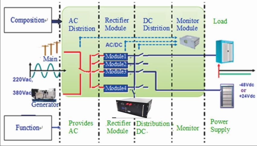
Multi-group Parallel use
If multiple systems are required in parallel, the positive electrodes of the output
terminals of several lithium-ion batteries are connected, and the negative be
connected with the negative. Please refer to the figure below.
Figure3-3 Three modules in parallel use
All Right Reserved ©
23Integrated Lithium-ion Battery Pack For Solar &
UPS User Manual 3 INSTALLATION GUIDE
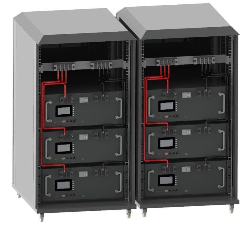
Figure3-4 Four modules in parallel use
All Right Reserved ©
24Integrated Lithium-ion Battery Pack For Solar &
UPS User Manual 3 INSTALLATION GUIDE
Figure3-5 Six modules in parallel use
Figure3-6 Eight modules in parallel use
All Right Reserved ©
25Integrated Lithium-ion Battery Pack For Solar &
UPS User Manual 3 INSTALLATION GUIDE
Switch power supply parameter setting
After installation, test whether there is a short-circuit phenomenon, if not, you can
directly on the electricity.
Switch power supply module parameters should be set according to the following
table:
Table3-5 Switch power supply parameter setting
Item Parameters Notes
Floating charge voltage 51.00V ~ 51.75V /
Uniform charge voltage 52.50V ~ 54.00V /
After the parameter is set up, it can be used normally, when the power outage, the
product is no delay to the communication equipment to provide back-up power supply
support.
1) Before the parallel installation, setting the battery to the limited charging mode is
very important. For detailed operations, please refer to Integrated Lithium-ion Battery
Pack PC Software User Manual, and it will be provided with this manual.
2) Capacity load (namely in line with the voltage-hysteresis current load), to ensure the
work, start the power supply module first, then load.
All Right Reserved ©
26Integrated Lithium-ion Battery Pack For Solar &
UPS User Manual 4 MAINTENANCE
4 MAINTENANCE
In order to ensure the lithium-ion battery pack achieves the longest life cycle, the
maintenance technician should carry out regular inspections and maintenance care.
The maintenance records should be complete and routine, so that subsequent verif
ication of management parameters of the battery pack can be tracked.
4.1 Electrical maintenance
Maintenance of the electrical parts may refer to table 4-1.
Table4-1 Table of contents for maintenance
Items The Methods Repair conditions Repair solution
checking
Points
Electrical Check if the Multimeter Battery voltage out of See the
Output of range set following
the voltage troubleshooting
is normal section
Fault Check if Visual Alarm
inspection lights are inspection
normal
Cable Insulation, Visual Insulation Replace the
Terminal inspection cracks, aging cable
Exfoliated, Replace the
corrosion of the terminal
terminals block
All Right Reserved ©
27Integrated Lithium-ion Battery Pack For Solar &
UPS User Manual 4 MAINTENANCE
4.2 Battery maintenance
Table4-2 Contents of battery maintenance
Frequency Items Solutions
Monthly Operating Stay away from heat source and avoid direct sunlight.
environment
Visual If there is any breakage, leakage or deformation,
inspection Isolate the problematic battery pack, take a
photograph and replace the battery.
Quarterly Visual Use cotton cloth to clean the appearance. Be careful
inspection during cleaning because the voltage is high.
Connection Check each terminal, check the bolt, if it’s loose,
status and tighten it again.
Check the reason if the cable temperature
exceeds 40℃.
Every 6 Measure At the final stage of charging, record the voltage;
months and record make sure the positive and negative voltage of the
the voltage battery are the same. Otherwise, should check
and repair the corresponding connection cable.
Collect the discharging data at least once every
six months for the first year.
In the second year, capacity is determined by
every three months. Through the RS232 interface
to view history, which shows frequent overcharge
of a battery in the alarm message, indicating that
the batteries have reached the charging and
discharging protection point. This may result in
time for preparing electricity is not enough and
suggest changing the battery immediately.
1) Charge and discharge status at the final stage can through capacity light to display.
Please refer to 2.2 for the definition of capacity lights.
4.3 Treatment for malfunctions
Solutions
Follow figure4-1 to process the malfunction.
All Right Reserved ©
28Integrated Lithium-ion Battery Pack For Solar &
UPS User Manual 4 MAINTENANCE
Figure4-1 Table of Battery maintenance
Step 1 Check the LED lights to detamine which part may fail.
Step 2 Check the information about faiure in the monitor module.
Step 3 Classify the information (DC, AC, modules, batteries, control, etc.).
Step 4 Find the problem according the information.
Step 5 Debuging the failure.
Step 6 Record the data while processing.
Step 7 Confirm all malfunction removed.
Step 8 Fill the report.
Step 9 Repeat these steps if any more malfunction.
All Right Reserved ©
29Integrated Lithium-ion Battery Pack For Solar &
UPS User Manual 4 MAINTENANCE
Faulty reasons and handling methods
Table 4-3 lists of most frequently failures and solutions.
Table4-3 Checklist
Failure Possible reasons Solutions
modes
Over DC over-voltage Check if the DC over-voltage alarm point
voltage alarm set (default value is 58.5V) is reasonable. If it
Unreasonable. is unreasonable, adjust according to the
In manual control actual situation.
mode, the power Check whether the manual control
supply voltage is increases the system voltage. If yes,
set too high. confirm the cause and return to the
Rectifier module normal value when the operation is
failure. completed.
Pull out the rectifier module one by one
to check whether the alarm disappears. If
the alarm still exists, insert the rectifier
module into the home position. If the
alarm disappears, replace the module.
Under No AC power. Check the DC under voltage alarm point
voltage Monitoring (default value is 45V). If it is not
module DC reasonable, adjust it according to the
undervoltage actual situation.
alarm point set Check that the power system current
unreasonable. value is greater than the current power
System system capacity and, if so, increase
configuration is capacity configuration or reduce the
unreasonable. power system load.
In manual control Check whether the manual control to
mode, the power reduce the system voltage, if so, should
supply voltage is confirm the reason, to be restored to
set too low. normal after the completion of the action.
Check whether Check whether the rectifier module is
the exchange of faulty and the system capacity does not
power outage meet the load demand. If yes, replace
and restore AC the rectifier module.
power supply.
Charge Module If there is a commutation module
over current communication communication interruption alarm, if yes,
interruption. plug and unplug the commutation module
Loose contact for of communication interruption to confirm
monitor module. whether the alarm is cleared. If the alarm
continues, replace the rectifier module.
Monitoring
failures. Reinstall the monitoring module, if still
alarm, replace the module.
All Right Reserved ©
30Integrated Lithium-ion Battery Pack For Solar &
UPS User Manual 4 MAINTENANCE
Failure Possible reasons Solutions
modes
Ambient Temperature Check if the ambient temperature alarm
temperature alarm parameter value (default 50 ℃) is reasonable. If
is too high setting is not, adjust it according to the actual
unreasonable. situation.
The temperature Check whether the temperature control
control system of system of the cabinet is faulty. If so,
the cabinet where handle the fault of the temperature
the temperature control system. When the temperature in
sensor is located the system cabinet returns to the normal
is faulty. range, the alarm will be cleared
The temperature automatically.
sensor is faulty. Check the temperature sensor is faulty, if
so, replace the temperature sensor.
Ambient Low temperature Check if the ambient temperature alarm
temperature alarm parameter value (default 0℃) is reasonable. If not,
is too low setting is adjust it according to the actual situation.
unreasonable. Check the system cabinet temperature
Temperature control system is faulty, if it is, then deal
sensor system with temperature control system failure.
cabinet where the After the temperature in the system
temperature cabinet returns to the normal range, the
control system alarm will be cleared automatically.
failure. Check that the ambient temperature
The temperature sensor is faulty and, if so, replace the
sensor is faulty. ambient temperature sensor.
Battery The battery Check the battery temperature is too high
temperature temperature is alarm value (default 53 ℃) is
is too high too high alarm reasonable, if unreasonable, according to
point set the actual situation adjustment.
unreasonable. Check the battery compartment
Battery temperature control system is faulty, and
compartment if so, then deal with temperature control
cooling system system failure. When the battery
failure. temperature returns to normal, the alarm
The temperature will be cleared automatically.
sensor is faulty. Check the temperature sensor is faulty,
and if so, replace the temperature
sensor.
All Right Reserved ©
31Integrated Lithium-ion Battery Pack For Solar &
UPS User Manual 4 MAINTENANCE
Failure Possible reasons Solutions
modes
Battery Battery Check if the battery temperature is too
temperature temperature is low (default: 0 ℃). If it is not reasonable,
is too low too low alarm set adjust the battery temperature according
unreasonable. to the actual situation.
Battery Check the battery compartment
compartment temperature control system is faulty, and
heating system if so, then deal with temperature control
failure. system failure. When the battery
The temperature temperature returns to normal, the alarm
sensor is faulty. will be cleared automatically.
Check the temperature sensor is faulty,
and if so, replace the temperature
sensor.
1) Only when the power system is configuredwith a battery temperature sensor there
should be a temperature alarm.
All Right Reserved ©
32Integrated Lithium-ion Battery Pack For Solar &
UPS User Manual 5 SPECIFICATIONS
5 SPECIFICATIONS
5.1 Technical specifications
Lithium batteries with 48V100Ah modules, the main technical indicators for a
single module is shown in table 5-1, 5-2, when performing multiple sets of parallel
battery, the charge and discharge parameters are shown in table 5-3, table 5-4.
Table5-1 Technical data of single module charging
Model Voltage Capacity Limited Charging current (A)
(V) (Ah) charging
voltage(V) Standard Largest
value value
Hubble X-100 48 100 54.0 20 100
Table5-2 A single module technology parameters
Model Voltages Capacity limited Discharging current (A)
(V) (Ah) discharge
voltage(V) Standard Biggest
value value
Hubble X-100 48 100 40.5 20 100
Table5-3 Multi group of parallel charging parameters
Voltage Capacity Limited charging voltage(V) largest Notes
(V) (Ah) current
smallest typical biggest (A)
value value value
48 100 50.3 51 54 20 1 parallels
48 200 50.3 51 54 40 2 parallels
All Right Reserved ©
33Integrated Lithium-ion Battery Pack For Solar &
UPS User Manual 5 SPECIFICATIONS
Voltage Capacity Limited charging voltage (V) largest Notes
(V) (Ah) current
smallest typical biggest (A)
value value value
48 300 50.3 51 54 60 3 parallels
48 400 50.3 51 54 80 4 parallels
48 500 50.3 51 54 100 5 parallels
48 600 50.3 51 54 120 6 parallels
48 700 50.3 51 54 140 7 parallels
48 800 50.3 51 54 160 8 parallels
Table5-4 Multi group of parallel discharging parameters
Voltage Capacity Limited discharge voltage(V) The Notes
(V) (Ah) largest
The The The current
smallest classical biggest (A)
value value value
48 100 40.5 42 43.5 30 1 parallels
48 200 43.2 42 43.5 60 2 parallels
48 300 43.2 42 43.5 90 3 parallels
48 400 43.2 42 43.5 120 4 parallels
48 500 43.2 42 43.5 150 5 parallels
48 600 43.2 42 43.5 180 6 parallels
48 700 43.2 42 43.5 210 7 parallels
48 800 43.2 42 43.5 240 8 parallels
5.2 The main performance index of the battery
For lithium battery of 48V100Ah module, the electrical performance as shown in table
5-3.
All Right Reserved ©
34Integrated Lithium-ion Battery Pack For Solar &
UPS User Manual 5 SPECIFICATIONS
Table5-5 Multiple group parallel discharge technology parameters
Items for test Testing methods Requirements
0.1C Standard battery charge, 1h within 1h Discharge time ≥ 600min
discharge with 0.1C discharge current to 40.5V,
performance Record the discharge time.
0.5C Standard battery pack, 1h within 0.5C Discharge time≥ 115min
discharge discharge current to 40.5V, record the
performance discharge time.
High After the battery pack is charged in Discharge time≥ 600min
temperature the standard (60 ± 2) ℃ high
performance temperature box for 4 hours and then
discharged to 40.5V at 0.1C, record
the discharge time.
Low After charging, the battery pack is put Discharge time≥ 180min
temperature in the low temperature box of(-10 ±
performance 2) ℃ for 6 hours, then discharged to
(-10 ℃) 40.5V at 0.2C at this temperature,
record the discharging time.
Low After charging, the battery pack is Discharge time≥ 120min
temperature allowed to stand for 6 hours at (-20 ±
performance 2) ℃, then discharged to 40.5V at
(-20 ℃) 0.2C at this temperature. Record
discharge time.
All Right Reserved ©
35Integrated Lithium-ion Battery Pack For Solar &
UPS User Manual 6 ENVIRONMENT PROTECTION
6 ENVIRONMENT PROTECTION
6.1 Environmental Label
The product described in this manual does not contain toxic and hazardous
substances or elements. It is a green product. It can be recycled after being
discarded and should not be discarded at will. The environmental label shown in
Table 6-1.
Table6-1 Environmental label
Specification Mark
48V
6.2 Recycle
This mark indicates that the product can not be classified with other waste. In
order to prevent potentially hazardous substances from hazardous waste disposal
hazards to the environment and human health, please refer to the classification of
waste recycling in order to promote the sustainable use of material resources.
In order to recycle the used equipment, please use the recycling system or
contact the manufacturer or seller of the product or the local authority to manage the
waste products.
All Right Reserved ©
36Integrated Lithium-ion Battery Pack For Solar &
UPS User Manual 7 APPENDIX
7 APPENDIX
7.1 Connection cable
If groups (4~10) of parallel sets of lithium batteries are not supplied by Battery
Manufacturer battery racks, you can choose the customized wiring cables to
replace. Relevant technical requirements are the feeder cable number and the
number of parallel battery pack is consistent, and the specifications of each
extension cable (length, diameter, and material) are the same.
For example, a customised six parallel wiring cable diagram as shown in figure7-1.
Figure7-1 Customized wiring cable diagram
According to the customer requirements, selecting the appropriate connector, cables,
extension cable specifications, refer to relevant cable specifications given in table 7-1.
All Right Reserved ©
37Integrated Lithium-ion Battery Pack For Solar &
UPS User Manual 7 APPENDIX
Table7-1 Corresponds to AWG line number table
AWG Diameter cross- Resistance Rated Maximum
sectional area (Ω/km) current current
mm inches (mm2) (A) (A)
0000 11.68 0.4600 107.22 0.17 423.2 482.6
000 10.40 0.4096 85.01 0.21 335.5 382.6
00 9.27 0.3648 67.43 0.26 266.2 303.5
0 8.25 0.3249 53.49 0.33 211.1 240.7
1 7.35 0.2893 42.41 0.42 167.4 190.9
2 6.54 0.2576 33.62 0.53 132.7 151.3
3 5.83 0.2294 26.67 0.66 105.2 120.0
4 5.19 0.2043 21.15 0.84 83.5 95.2
5 4.62 0.1819 16.77 1.06 66.2 75.5
6 4.11 0.1620 13.30 1.33 52.5 59.9
7 3.67 0.1443 10.55 1.68 41.6 47.5
8 3.26 0.1285 8.37 2.11 33.0 37.7
9 2.91 0.1144 6.63 2.67 26.2 29.8
10 2.59 0.1019 5.26 3.36 20.8 23.7
11 2.30 0.0907 4.17 4.24 16.5 18.8
12 2.05 0.0808 3.332 5.31 13.1 14.9
13 1.82 0.0720 2.627 6.69 10.4 11.8
14 1.63 0.0641 2.075 8.45 8.2 9.4
Installation steps are shown below:
1) Preparation before installing: insulation metal mounting tool (such as a cross
screwdriver, wrench), insulation tape and customized wiring cables.
2) Lithium-ion battery pack should be installed in a suitable location.
3) Connect each connector in turn with each of the output end of the lithium-ion
battery pack. First, connect all lithium-ion battery packs with to the positive
terminals (“+”), and then all the negative terminals of lithium-ion battery packs.
All Right Reserved ©
388 G-SENSOR The G-Sensor is a built in ANTI-THEFT feature. By default the G-SENSOR is in a disabled state and can not be enabled through the front display. The G-Sensor is reserved for commercial installtions and can only be enabled through specialist software if required. Please contact your installer is this is a requirement. Attention On purchasing the products, services or features, such as international commercial contracts, you accept and are bound by the terms described in this document, in part or in whole, the product, services or features are strictly for your own purchase or use. Unless otherwise agreed in the contract, Supplier does not make any express or implied representations or warranties within the content of this document. For product version upgrades or other reasons, this document will not be updating on a regular basis. Unless otherwise agreed, this document serves only as a guide, all the statements in this document, information and recommendations do not constitute any express or implied warranty.
You can also read