New diagonal micropolarizer arrays designed by an improved model in fourier domain
←
→
Page content transcription
If your browser does not render page correctly, please read the page content below
www.nature.com/scientificreports
OPEN New diagonal micropolarizer arrays
designed by an improved model
in fourier domain
Jia Hao1,2,3, Yan Wang1,2,3, Kui Zhou1,2,3, Xiaochang Yu1,2,3 & Yiting Yu1,2,3*
The design of micropolarizer array (MPA) patterns in Fourier domain provides an efficient approach
to reconstruct and investigate the polarization information. Inspired by Alenin’s works, in this paper,
we propose an improved design model to cover both 2 × N MPAs and other original MPAs, by which
an entirely new class of MPA patterns is suggested. The performance of the new patterns is evaluated
through Fourier domain analysis and numerical simulations compared with the existing MPAs.
Particularly, we analyze the reconstruction accuracy of the first three Stokes parameters and degree
of linear polarization (DoLP) in detail. The experimental results confirm that the 2 × 2 × 2 MPA provides
the highest reconstruction quality of s0, s1, s2 and DoLP in terms of quantitative measures and visual
quality, while the 3 × 3 diagonal MPA achieves the state-of-the-art best results in case of single-
snapshot systems. The guidance of this extended model and new diagonal MPAs show its massive
potential for the division of focal plane (DoFP) polarization imaging applications.
At present, the most attractive polarization imaging instrument employs the way of division of focal plane
(DoFP), in which a micropolarizer array (MPA) is placed in front of the camera’s focal plane, showing the
advantages of simple structure, compact size and the capability of real-time d etection1,2. The first polarization
imaging system which had been built using the conventional 2 × 2 repeating pattern of polarization analyzer,
was introduced by Chun3 in 1994 and has been a standard for almost 20 years. However, since each pixel within
a 2 × 2 minimum periodic array can only collect the intensity information of its corresponding polarization
orientation4, the spatial resolution is reduced, and the reconstructed polarization information is not accurate
due to the instantaneous field of views (IFOV)5,6. Therefore, it is significant to enhance the quality of polarization
reconstruction images for further applications.
Until now, various methods have been developed for the quality enhancement of polarization reconstruction
images. Subsequently, several works have demonstrated that both the layout of MPAs and the reconstruction
algorithms affect the quality of the reconstructed Stokes parameter images7–11. Furthermore, some unconven-
tional MPA p atterns7,8 and interpolation m
ethods6,9–11 have been proposed to achieve superior resolution and
accurate polarization information. For example, in 2014, LeMaster and Hirakawa7 creatively put forward a novel
2 × 4 MPA pattern, which demonstrated that the high reconstruction quality could be achieved over the tradi-
tional 2 × 2 MPA. For further exploration, in 2017, Alenin et al.8 designed 2 × 3, 2 × 7 and 2 × 2 × 2 MPA patterns
for linear DoFP polarimeters, and extended the 2 × 4 MPA into a family of 2 × N MPAs aiming to widen the
optimization space in Frequency Domain. The results indicated that the maximized theoretical spatial resolu-
tion of the reconstructed Stokes parameters could be achieved by the 2 × 2 × N MPAs. Despite their previous
superior efforts advanced the available set of MPA patterns and improved the reconstruction quality of Stokes
parameters and degree of linear polarization (DoLP) images, however, these works were merely focused on the
family of 2 × N patterns, and although the 2 × 2 × N MPAs have superior performance in reconstruction quality,
these MPAs should be used in multiple-snapshots systems. Besides, to the best of our knowledge, the applica-
tion of a generalized model to investigate new MPA layouts for improving reconstruction accuracy has not
been reported. Therefore, for the purpose of a higher reconstruction quality in case of single-snapshot systems,
designing higher-performance MPA patterns for linear DoFP polarimeters is required.
Motivated by the extraordinary design model8, in this paper, we propose an improved model that can be
leveraged to design both the 2 × N MPA patterns and N × N diagonal MPA patterns by changing the location of
carriers in Fourier domain. Moreover, to compare the performance of those previously demonstrated MPAs with
1
Research & Development Institute of Northwestern Polytechnical University in Shenzhen, Shenzhen 518057,
China. 2Key Laboratory of Micro/Nano Systems for Aerospace (Ministry of Education), Northwestern Polytechnical
University, Xi’an 710072, China. 3Shaanxi Province Key Laboratory of Micro and Nano Electro‑Mechanical Systems,
Northwestern Polytechnical University, Xi’an 710072, China. *email: yyt@nwpu.edu.cn
Scientific Reports | (2021) 11:5778 | https://doi.org/10.1038/s41598-021-85103-x 1
Vol.:(0123456789)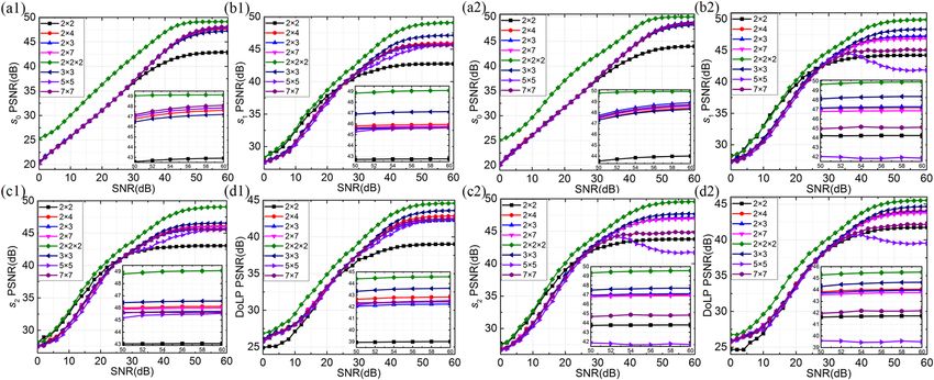
www.nature.com/scientificreports/
Figure 1. Eight MPA patterns and their corresponding Discrete Fourier Transform (DFT) spectra. The first
row represents the (a1) conventional 2 × 23 (b1) LeMaster’s 2 × 47, (c1) Alenin’s 2 × 38, (d1) Alenin’s 2 × 78, (e1)
Alenin’s 2 × 2 × 28, (f1) this work’s 3 × 3, (g1) this work’s 5 × 5, (h1) this work’s 7 × 7. The second row gives the
spectra according to MPAs in the first row.
the entirely new class of N × N diagonal MPAs, we provide a detailed comparison of the reconstruction quality
in s0, s1, s2 and DoLP simultaneously. The results demonstrate that this improved model can further expand the
scope of MPAs and effectively design a new type of patterns with higher performance, which may bring a great
applications for the DoFP polarization detection technique.
Methodology and design
Design model of MPAs. Stokes vector S has been proven to be efficient for representing the polarization
states of incident light1. For DoFP systems, most digital cameras combine a photodetector with a MPA to capture
the incident light. Then the Stokes vector can be indirectly calculated using the acquired intensity images from
different polarization orientations. Traditionally, it is formulated as:
� ��
s0 I0◦ + I45◦ + I90◦ + I135◦ 2
s I ◦ −I ◦
S = 1 = 0 ◦ 90 ◦ , (1)
s2 I45 − I135
s3 IR − IL
where I0°, I45°, I90°, and I135° represent the intensities measured through a linear polarizer in the directions of 0°,
45°, 90°, and 135°, respectively, and s3 is always ignored for linear DoFP polarimeters13.
To derive Stokes parameters, the captured image I is given using a series of pre-determined analyzing polari-
zation states, AN8,
T T
TS T + n
I = I1 · · · IN = A 1 S · · · AN
(2)
= WS + n,
where IN represents the intensity of the polarized light passing through the linear polarizer, S represents the
unknown polarization state, and n represents an additive detector noise. Then the unknown state’s Stokes param-
eters can be revealed by,
S = W+ I = W+ WS + W+ n,
(3)
where S represents the calculated Stokes parameters and “+” in the upper right corner denotes the pseudo-inverse
of a matrix. Because the layout of the MPA is periodic and defined by the square lattice, it is convenient to design
polarization orientations of MPAs using an analysis vector. The conventional and most commonly used 2 × 2
MPA, as shown in Fig. 1a1, and the available set of 2 × N MPAs, as shown in Fig. 1b1–e1 can be expressed by
using the analyzing v ector8,
1 2 1 1
Am,n = cos (mπ) + cos (nπ) , or Am,n = cos (amπ) cos (bnπ) , (4)
4 cos (mπ) − cos (nπ) 2 sin (amπ ) cos (bnπ)
where m and n are the horizontal and vertical pixel coordinates in a MPA pattern, respectively. The polarization
orientations of each pixel can be calculated by changing the m and n, while a and b determine the positioning
of carriers in horizontal and vertical direction, respectively.
Inspired by the above design model, we propose a new generalized model, which breaks the limit of Eq. (4)
and can be used to design a novel type of MPAs with N × N diagonal configuration. The permutation of three
N × N diagonal MPAs, as s hown in Fig. 1e1–g1, belong to the following analyzing vector,
Scientific Reports | (2021) 11:5778 | https://doi.org/10.1038/s41598-021-85103-x 2
Vol:.(1234567890)www.nature.com/scientificreports/
Type Origin Size a b c N CNa 2
σ0,1,2,3b
QT Q+
√
Chun 3 2×2 – – – 1 2 1, 4, 4,
√
LeMaster 7 2×4 4 2 1 1 2 1, 4, 4,
2×N √
Alenin 8 2×3 3 1.5 1 1 2 1, 4, 4,
√
Alenin 8 2×7 7 3.5 2 1 2 1, 4, 4,
√
Alenin 8 2×2×2 2 1 1 2 2 1
2 , 4, 4,
√
This work 3×3 3 1 1 1 2 1, 4, 4,
Diag N × N √
This work 5×5 5 2 2 1 2 1, 4, 4,
√
This work 7×7 7 3 3 1 2 1, 4, 4,
Table 1. Notable micropolarizer array patterns. The circles represent the coefficient’s polar form of the
frequency phase matrix, and the total number of circles is 9 × 4 = 36. The direction of the radius line in the
circles represents the phase information as: right = + 1, up = + j, left = − 1, down = − j. The frequency phase
matrix in Eq. (7) indicates that there have nine channels, which contain four empty channels and five non-
empty channels. Empty circles indicate that the locations of the channels do not contain the information of
Stokes parameter8. a CN is the condition number, which ensures the optimal configuration for W12. b σ20,1,2,3 are
the noise variances from Q, which is a 9 × 4 matrix; the EWV is the sum of σ20,1,2,3.
1 � �
1
Am,n = cos 2π (bm + cn) , (5)
2 sin � 2πa (bm + cn)�
a
by which, both the LeMaster’s 2 × 4 MPA and Alenin’s 2 × N MPAs can also be designed by setting the appropri-
ate parameters. As shown in Table 1, the corresponding parameters of the 2 × N MPAs and the N × N diagonal
MPAs are discussed in greater detail.
The intensity measured through linear polarizer with different directions can be represented by,
Iθ = (s0 + s1 cos 2θ + s2 sin 2θ)/2, (6)
where θ represents the orientation angle of analyzer at different location. According to the Eqs. (5) and (6), it is
convenient to calculate the orientation angles of the MPAs designed by our proposed model.
MPA’s performance evaluations. As shown in Alenin’s seminal w ork8, the Fourier transform of Eq. (5)
can be denoted by the Frequency Phase Matrix (FPM) to describe the corresponding channel structure, which
provides new insights into MPA patterns design,
1
� �, η)
2 δ(ξ � � ��
1
Âξ ,η = δ ξ + ab , η + ac + δ ξ − ab , η − ac , (7)
4� � � � ��
j b c b c
4 δ ξ + a , η + a − δ ξ − a , η − a
where a, b and c determine the positioning of carriers in Fourier domain.
For the purpose of analyzing the proposed model theoretically, we use the Q formalism to analyze the
Stokes polarimeters, which can reveal the relationship between the Stokes parameters and the set of channel
structures8,13. By properly inverting process, the Stokes vector can also be reconstructed by,
S = F −1 Q+ F{C} , (8)
where Q+ is the pseudo-inverse of Q, and C is the related channel. Accordingly, the parameters of MPAs designed
by Eq. (5), the corresponding channel structures indicated by the Q matrix and its inverse are all shown in Table 1.
Based on the Alenin’s t heory14, to assess the performance of a MPA while taking the noise, bandwidth, and
system error into consideration, using the equally weighted variance (EWV) inferred by Q+ as an index is signifi-
cant. It provides a handy way to evaluate the intrinsic properties of the channel structure. As shown in Table 1,
the family of N × N diagonal MPAs has the same value of EWV as the family of 2 × N MPAs. In particular, we
can also design the 2 × 2 × 2 MPA with the setting of a = 2 and b = c = 1 in our proposed model, whose EWV is
equal to 8.5. Although this type of MPA extends the channel centers to the outer corners and provides a strong
capability of noise resilience, this MPA cannot reconstruct the first three Stokes parameters in real-time8. To
obtain all the mentioned Stokes parameters simultaneously, it must add a temporally modulated ferroelectric
liquid crystal rotator. As an appropriate metric, the concept of EWV can be used to evaluate the performance
Scientific Reports | (2021) 11:5778 | https://doi.org/10.1038/s41598-021-85103-x 3
Vol.:(0123456789)www.nature.com/scientificreports/
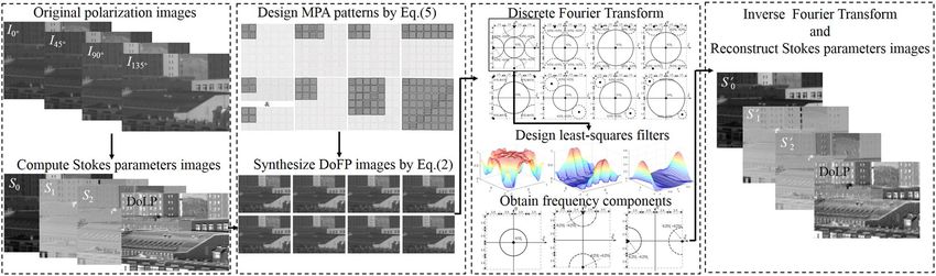
Figure 2. Flowchart for reconstructing the images of different Stokes parameters.
and assess noise immunity. However, the bandwidth also has an effect on the quality of reconstruction, which
improves when the higher frequency information is included. Therefore, the design of MPA patterns should
take into account various factors comprehensively, and the effective analysis of the bandwidth of s0, s1 and s2 is
significant for evaluating the MPA’s performance.
As shown in Fig. 1, it is noticeable that the spectra have several multiplex frequency components different
by the location and the bandwidth in Fourier domain. White solid lines outline the channel bandwidths of
s0, and white dotted lines outline the channel bandwidths of multiplex components of s1 and s2. Note that by
convention, the basebands are placed at the center in the second row, but all the DFT spectra are periodic in
both horizontal and vertical directions. Based on the Fourier domain representation, it is intuitive and visual
to analyze the location of multiplex frequency components, the extent of aliasing contaminations and relative
bandwidths between different components. As shown in Fig. 1a2, we can easily discover that the conventional
2 × 2 MPA has a small theoretical bandwidth of s0, because the frequency components overlap on the horizontal
and vertical axes. Obviously, as shown in Fig. 1b2–h2, the 2 × N MPAs and N × N diagonal MPAs remarkably
reduce the risk of aliasing and improve the bandwidth of s0 by further separating s1 and s2 carriers away from
the s0 carrier. Therefore, these MPAs can significantly reduce the crosstalk impact of different components and
improve the reconstruction quality as the theoretical bandwidth of s0 increases. Similarly, we can analyze the
theoretical bandwidth of s1 and s2 with the same approach. Avoiding the frequency components situated on
the horizontal and vertical axes, the reconstruction accuracy of s1 and s2 increases strikingly as the theoretical
bandwidth increases. Based on these analyses, we can see that the 2 × 2 × 2 MPA provides the best s0, s1 and s2
reconstruction accuracy in case of multiple-snapshots systems, while the 7 × 7 diagonal MPA provides the best
s0 reconstruction accuracy in case of single-snapshot systems theoretically. Furthermore, the quality of the DoLP
should be weighed depending on various factors comprehensively.
Experimental validation
Reconstruction method. To provide a quantitative comparison of different MPA patterns, numerical
simulations are also performed to evaluate the imaging quality of reconstruction. Based on Junchao Zhang’s
database15, we simulated the reconstructed performance of Stokes parameters and DoLP through visual and
quantitative measurement by comparing three new N × N diagonal MPA patterns with several mainstream MPA
patterns such as 2 × 23, 2 × 47, 2 × 38, 2 × 78, 2 × 2 × 28. The scheme for the reconstruction of Stokes parameters and
DoLP images is described in Fig. 2, which contains four main steps: (1) by applying the true intensity images of
I0°, I45°, I90° and I135°, we can calculate the Stokes parameters and DoLP images as the true samples; (2) by combin-
ing different MPA patterns as shown in Fig. 1, we generate the synthesized DoFP images from the true Stokes
parameters images of s0, s1 and s2; (3) through Discrete Fourier Transform(DFT) and frequency domain filtering,
we get three frequency components, respectively; (4) by employing the Inverse Fourier Transform (IFT), we can
reconstruct the Stokes parameters and DoLP images in the end.
To reconstruct the Stokes parameters and DoLP from the synthesized image, the reconstruction algorithm
and filtering operation must be a pplied9,16. As shown in Fig. 1, the appropriate band-pass filters must be used to
estimate the frequency components from different locations and bandwidths. Like the color filter array (CFA)
designing and reconstructing process17,18, we want to note that the algorithms also profoundly affect the recon-
struction quality. Instead of developing extremely complex reconstruction algorithm, in this paper we focus on
new diagonal MPAs design and the comparison of the MPA’s inherent attribute. Considering that the practical
bandwidths occupied by the frequency components are diverse for different scene targets and different MPAs,
the filters based on the least-square method have more powerful abilities to be suited for various scenes and
MPAs. Inspired by the reconstruction process for the Bayer CFA19,20, in this paper, we used the reconstruction
algorithm based on the least-square filters to reconstruct Stokes parameters and DoLP. In order to estimate for the
components s0, s1, and s2 by the filtering operation, the corresponding filters h1, h2, h3 were separately optimized
according to the scenes and MPA patterns we mentioned. Formally, the least-square filters can be expressed by,
Scientific Reports | (2021) 11:5778 | https://doi.org/10.1038/s41598-021-85103-x 4
Vol:.(1234567890)www.nature.com/scientificreports/
Figure 3. Reconstructed DoLP images of different MPA patterns on the building1 scene. The left side
represents the (a1) 2 × 2, (b1) 2 × 4, (c1) 2 × 3, (d1) 2 × 7, (e1) 2 × 2 × 2, (f1) 3 × 3, (g1) 5 × 5, (h1) 7 × 7, and (i1)
ground-truth. The right side gives the enlarged views of white rectangular regions of the reconstructed images
and ground-truth image according to MPAs in the left side.
Figure 4. Reconstructed DoLP images of different MPA patterns on the building2 scene. The left side
represents the (a1) 2 × 2, (b1) 2 × 4, (c1) 2 × 3, (d1) 2 × 7, (e1) 2 × 2 × 2, (f1) 3 × 3, (g1) 5 × 5, (h1) 7 × 7, and (i1)
ground-truth. The right side gives the enlarged views of white rectangular regions of the reconstructed images
and ground-truth image according to MPAs in the left side.
2
h′x = arg min fx − fˆx
h
2 (9)
= arg min fx − I MPA ∗ hx ,
h
where h′x represents the obtained band-pass filters h1, h2 and h3 which are used to estimate the modulated fre-
quency components in Fourier domain, respectively. The fx is the original signal obtained by the full resolution
ground-truth images and fˆx represents the estimated signal.
As shown in Figs. 3i1 and 4i1, two target scenes were used to evaluate the reconstructed performance. Nota-
bly, the white rectangular regions of the ground-truth image were expanded and presented in Figs. 3a2–i2 and
4a2–i2. To facilitate the objective comparisons, the peak-signal-to-noise-ratio (PSNR)21 was used as a quantita-
tive evaluation criterion in this paper, which is the most common measure to assess the performance of spatial
resolution enhancement. The calculation formula of PSNR is defined as:
PSNR = 10 log10 (MAX2 /MSE). (10)
In order to give a comprehensive evaluation, the gradient magnitude similarity deviation (GMSD)22 was also
used to measure the quality of reconstructed images, which makes use of global variation of gradient based local
quality map for the overall image quality prediction
Scientific Reports | (2021) 11:5778 | https://doi.org/10.1038/s41598-021-85103-x 5
Vol.:(0123456789)www.nature.com/scientificreports/
PSNR reconstruction results GMSD reconstruction results (× 10–9)
2×2 2×4 2×3 2×7 2×2×2 3×3 5×5 7×7 2×2 2×4 2×3 2×7 2×2×2 3×3 5×5 7×7
Building1
S0 42.96 47.73 48.23 47.98 49.13 47.30 47.96 48.23 406.80 10.41 7.65 10.16 6.13 19.88 10.89 9.41
S1 42.76 45.95 45.66 45.78 49.13 47.15 45.66 45.65 1193.7 285.31 326.06 256.68 67.38 138.81 153.97 272.34
S2 43.05 46.13 45.72 46.04 49.10 46.57 45.55 45.63 817.44 218.10 274.95 215.26 67.99 157.78 168.77 219.93
DoLP 39.03 42.87 42.26 42.44 44.62 43.63 42.56 42.43 2422.8 335.07 583.30 443.28 148.40 238.67 284.84 500.02
Building2
S0 44.07 48.58 49.09 48.76 49.94 48.44 48.76 48.90 150.46 9.99 6.45 8.11 5.54 10.97 7.31 6.60
S1 44.26 47.22 47.30 46.87 49.94 48.41 41.79 45.08 755.34 181.82 295.94 256.73 80.00 165.71 187.60 246.56
S2 43.78 47.04 47.13 46.92 49.60 47.73 41.64 44.81 644.61 176.03 204.82 166.55 67.29 143.97 177.70 215.50
DoLP 41.76 44.07 43.98 43.78 45.55 44.69 39.45 42.17 1120.4 377.14 552.26 433.73 199.65 359.87 418.35 566.17
Table 2. Reconstruction results with different MPAs.
N
1
GMSD =
(GMS(i) − GMSM), (11)
N
i=1
where N represents the total number of pixels in the image. GMS represents the gradient magnitude similarity
map and GMSM is the average of GMS. In general, the larger PSNR value is, the higher reconstruction accuracy
will be, while a smaller GMSD value indicates that the reconstruction is of higher quality.
Results and discussions
The value of PSNR and GMSD used for comparison are shown in Table 2, and the best results in each row are
in boldface and underlined among the proposed MPA layouts. For the single-snapshot systems, the best results
in each row are highlighted in bold, to indicate the best reconstruction performance among the single-snapshot
layouts. It is obvious from Table 2 that the 2 × 2 × 2 MPA provides the best s0, s1, s2 accuracy and DoLP accuracy
in all scenes, which is consistent with the theoretical analysis. Besides, the new N × N diagonal MPAs provide
better Stokes parameters and DoLP reconstruction accuracy than the conventional 2 × 2 MPA in the building1
scene. In particular, the new 5 × 5 diagonal MPA provides the worst DoLP reconstruction accuracy in the build-
ing2 scene, which indicates that the frequency structure is particularly associated with the MPA pattern and
the scenes. In addition, according to the PSNR and GMSD results, the 2 × 3 MPA can reconstruct the s0 with a
higher accuracy than other single-snapshot layouts, and the 7 × 7 diagonal MPA comes second. Note that if we
need to reconstruct Stokes parameters and DoLP images in case of single-snapshot systems, the 3 × 3 diagonal
MPA provides the best s1, s2, and DoLP accuracy in all scenes, which demonstrates that our proposed new 3 × 3
diagonal MPA reconstructs state-of-the-art results. Moreover, the reconstructed DoLP images are shown in
Figs. 3a1–i1 and 4a1–i1, and the enlarged views of the reconstructed images and ground-truth image are shown
in Figs. 3a2–i2 and 4a2–i2 for visual comparison. As shown in Figs. 3 and 4, we can see that the reconstructed
DoLP image by 2 × 2 × 2 MPA is much cleaner while preserving image details and edges, removing aliasing
artifacts and reducing the zipper effect artifacts. However, in case of single-snapshot systems, it is seen that the
quality of the DoLP image achieved by 3 × 3 diagonal MPA is much better. On the contrary, it can be seen clearly
that the loss of image details and the generation of false grid exists in other reconstructed DoLP images. Thus, the
novelty diagonal MPAs proposed in this paper can enhance the quality of the reconstruction images effectively,
and our improved model has great value for DoFP polarization imaging.
Finally, to compare the capability of denoising, we first add Gaussian noise to the original images. Then the
corresponding reconstructed images are generated using the different MPAs. Similarly, the PSNR is used to
evaluate the reconstruction performance, and the level of the additional noise represented by the signal-to-noise
ratio (SNR) is increased by every 2 dB from 0 to 60 dB. The corresponding PSNR curves are drawn in Fig. 5.
Experimental results show that the value of PSNR increases as the SNR increases. For a low SNR, all the MPAs
behave a similar s1, s2 and DoLP reconstruction performance, because all the filters are narrow and have a similar
size. However, the 2 × 2 × 2 MPA provides the highest s0 reconstruction accuracy due to the most bandwidth. As
the SNR increases, the filters are widened to include more frequency information. The 2 × 2 × 2 MPA gives the
best s0, s1, s2 and DoLP reconstruction quality, and the 2 × 2 MPA exhibits the worst performance in the building1
scene. Unlike this trends, the 5 × 5 diagonal MPA exhibits the worst s1, s2 and DoLP reconstruction performance
in the building2 scene. It worth noting that the relative bandwidth may behave flexible size in Fourier domain for
different scenes8, which means the proposed MPAs may highlight their advantages and properly be applied to
reconstruction, when the s0, s1 and s2 channels require less or more bandwidth. As the SNR reaches a high enough
level, it is expected that the PSNR curves keep stable. In this case, a larger filter can result in a grid effect, due to
the high-frequency content mixing in the extractive information. In contrast, a narrower filter leads to excessive
blurring because of the information missing. All in all, the 2 × 2 × 2 MPA provides the best s0, s1, s2 and DoLP
accuracy, while the 3 × 3 diagonal MPA designed by the improved model achieves state-of-the-art results in case
of achieving the Stokes parameters s1, s2 and DoLP in the single-snapshot systems, which demonstrates that our
improved design model can efficiently find new MPA patterns for enhancing the quality of reconstruction images.
Scientific Reports | (2021) 11:5778 | https://doi.org/10.1038/s41598-021-85103-x 6
Vol:.(1234567890)www.nature.com/scientificreports/
Figure 5. Convergent curves of the PSNR on the testing scenes with different MPA patterns. The left side on the
building1 scene represents the (a1) PSNR value of s0, (b1) PSNR value of s1, (c1) PSNR value of s2, (d1) PSNR
value of DoLP; the right side on the building2 scene represents the (a2) PSNR value of s0, (b2) PSNR value of s1,
(c2) PSNR value of s2, (d2) PSNR value of DoLP.
Conclusions
In conclusion, we propose an improved design model for constructing richer MPA patterns. This model is based
on leveraging the Fourier domain and designing information carriers that yield optimal bandwidth, which can
extend the 2 × N MPAs into an entirely new family of N × N diagonal MPAs. Both visual and quantitative measure-
ments are applied to evaluate the reconstructed performance and denoising performance of s0, s1, s2 and DoLP.
The experimental results show that the quality of s0, s1, s2 and DoLP reconstruction is significantly improved in
terms of quantitative measures and visual quality by 2 × 2 × 2 MPA. If we need to reconstruct the Stokes param-
eters s1, s2 and DoLP simultaneously in case of a single-snapshot system, the 3 × 3 diagonal MPA achieves the
state-of-the-art best results. This improved model widens the optimization space and can construct a number of
available MPAs, which may further facilitate the practical applications of the DoFP technique.
Received: 17 November 2020; Accepted: 25 February 2021
References
1. Tyo, J. S., Goldstein, D. L., Chenault, D. B. & Shaw, J. A. Review of passive imaging polarimetry for remote sensing applications.
Appl. Opt. 45, 5453 (2006).
2. Wu, Z., Powers, P. E., Sarangan, A. M. & Zhan, Q. W. Optical characterization of wiregrid micropolarizers designed for infrared
imaging polarimetry. Opt. Lett. 33, 1653 (2008).
3. Chun, C. S. L., Fleming, D. L. & Torok, E. J. Polarization-sensitive thermal imaging. Proc. SPIE 2234, 275 (1994).
4. Zeng, X. L., Luo, Y., Zhao, X. J. & Bin, W. An end-to-end fully-convolutional neural network for division of focal plane sensors to
reconstruct S0, DoLP, and AoP. Opt. Express 27, 8566 (2019).
5. Fei, H., Li, F. M., Chen, W. C., Zhang, R. & Chen, C. S. Calibration method for division of focal plane polarimeters. Appl. Opt. 57,
4992 (2018).
6. Ratliff, B. M., Lacasse, C. F. & Tyo, J. S. Interpolation strategies for reducing IFOV artifacts in microgrid polarimeter imagery. Opt.
Express 17, 9112 (2015).
7. Lemaster, D. A. & Hirakawa, K. Improved microgrid arrangement for integrated imaging polarimeters. Opt. Lett. 39, 1811 (2014).
8. Alenin, A. S., Vaughn, I. J. & Tyo, J. S. Optimal bandwidth micropolarizer arrays. Opt. Lett. 42, 458 (2017).
9. Mihoubi, S., Lapray, P. J. & Bigué, L. Survey of demosaicking methods for polarization filter array images. Sensors 18, 3688 (2018).
10. Wen, S. J., Zheng, Y. Q., Lu, F. & Zhao, Q. P. Convolutional demosaicing network for joint chromatic and polarimetric imagery.
Opt. Lett. 44, 5646 (2019).
11. Zhang, J. C., Luo, H. B., Hui, B. & Chang, Z. Image interpolation for division of focal plane polarimeters with intensity correlation.
Opt. Express 24, 20799 (2015).
12. Tyo, J. S. Design of optimal polarimeters: Maximization of signal-to-noise ratio and minimization of systematic error. Appl. Opt.
41, 619 (2002).
13. Kupinski, M., Bradley, C., Diner, D., Xu, F. & Chipman, R. Angle of linear polarization images of outdoor scenes. Opt. Eng. 58,
082419 (2019).
14. Alenin, A. S. & Tyo, J. S. Generalized channeled polarimetry. J. Opt. Soc. Am. A 31, 1013 (2014).
15. Zhang, J. C. et al. Sparse representation-based demosaicing method for microgrid polarimeter imagery. Opt. Lett. 43, 3265 (2018).
16. Jiang, Z. X. et al. Reconstructing Stokes parameters from non-uniform division-of-focal-planemodulation. Opt. Lasers Eng. 134,
10699 (2020).
17. Lian, N. X., Chang, L., Tan, Y. P. & Zagorodnov, V. Adaptive filtering for color filter array demosaicking. IEEE Trans. Image Process.
16, 2515 (2007).
18. Fang, L. et al. Joint demosaicing and subpixel-based down-sampling for bayer images: A fast frequency-domain analysis approach.
IEEE Tran. Multimed. 14, 1359 (2012).
19. Dubois, E. Frequency-domain methods for demosaicking of Bayer-sampled color images. IEEE Signal Process. Lett. 12, 847 (2005).
Scientific Reports | (2021) 11:5778 | https://doi.org/10.1038/s41598-021-85103-x 7
Vol.:(0123456789)www.nature.com/scientificreports/
20. Leung, B., Jeon, G. & Dubois, E. Least-squares luma–chroma demultiplexing algorithm for Bayer demosaicking. IEEE Trans. Image
Process. 20, 1885 (2011).
21. Zhou, W. & Bovik, A. C. Mean squared error: Love it or leave it? A new look at Signal Fidelity Measures. IEEE Signal Process. Mag.
26, 98 (2009).
22. Xue, W. F., Zhang, L., Mou, X. Q. & Alan, C. B. Gradient magnitude similarity deviation: A highly efficient perceptual image quality
index. IEEE Trans. Image Process. 23, 2 (2014).
Acknowledgements
We acknowledge the Science, Technology and Innovation Commission of Shenzhen Municipality
(JCYJ20180508151936092), the National Natural Science Foundation of China (51975483), and the Key Research
Projects of Shaanxi Province (2020ZDLGY01-03).
Author contributions
J.H. and Y.Y. conceived the idea of this work, and J.H. performed the design model and theoretical analysis;
J.H., Y.W. and K.Z. made the numerical simulations and data analysis; K.Z. and X.Y. assisted the experiments
and helped in checking the data. The manuscript is written by J.H., edited by Y.Y., and revised by all authors.
Competing interests
The authors declare no competing interests.
Additional information
Correspondence and requests for materials should be addressed to Y.Y.
Reprints and permissions information is available at www.nature.com/reprints.
Publisher’s note Springer Nature remains neutral with regard to jurisdictional claims in published maps and
institutional affiliations.
Open Access This article is licensed under a Creative Commons Attribution 4.0 International
License, which permits use, sharing, adaptation, distribution and reproduction in any medium or
format, as long as you give appropriate credit to the original author(s) and the source, provide a link to the
Creative Commons licence, and indicate if changes were made. The images or other third party material in this
article are included in the article’s Creative Commons licence, unless indicated otherwise in a credit line to the
material. If material is not included in the article’s Creative Commons licence and your intended use is not
permitted by statutory regulation or exceeds the permitted use, you will need to obtain permission directly from
the copyright holder. To view a copy of this licence, visit http://creativecommons.org/licenses/by/4.0/.
© The Author(s) 2021
Scientific Reports | (2021) 11:5778 | https://doi.org/10.1038/s41598-021-85103-x 8
Vol:.(1234567890)You can also read