New Years Eve Ball Drop - Created by Ruiz Brothers Last updated on 2019-09-20 05:24:27 PM UTC - Adafruit Industries
←
→
Page content transcription
If your browser does not render page correctly, please read the page content below
New Years Eve Ball Drop
         Created by Ruiz Brothers

Last updated on 2019-09-20 05:24:27 PM UTC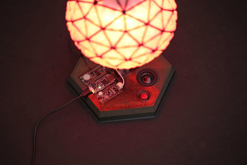
Overview

Since 1907, the Times Square Ball (https://adafru.it/Dtu) has been an annual spectacle that signals in the New Year.
Commonly referred to as the ball drop, this 12-ft diameter glowing geodesic sphere descends from a flagpole at
11:59pm and takes 60 seconds. The ball itself has been redesigned over the years to reflect the latest in lighting
technology.

DIY Ball Drop
This project is a scale replica of the Time Square Ball. It features a 180mm (7 inch) 3D printed geodesic sphere that is
illuminated with NeoPixel LEDs. The ball is supported by a 2020 aluminum extrusion and suspended via a pulley and
linear rail. A continuous servo turns and unwinds a rope tied to the ball allowing it to be lowered and raised. An on-
board speaker at the base plays "Auld Lang Syne (https://adafru.it/DtM)" synonymous as the New Years Eve Anthem.

 © Adafruit Industries              https://learn.adafruit.com/new-years-eve-ball-drop                      Page 5 of 46
As the ball is lowered, a 10-sec countdown occurs followed by fireworks, crowd cheering and music playing.

When the device is triggered the neopixels cycle through colors illuminating the ball. The geodesic sphere can
smoothly slide up and down the railing with the aid of precision ball bearings.

The build is mostly comprised of 3D printed brackets, fixtures and adapters with some additional hardware and
supplies.

Electronic Components

     Adafruit Feather M4 Express (https://adafru.it/Cmy)
     RTC Precision FeatherWing (https://adafru.it/wiD)
     Prop-Maker FeatherWing (https://adafru.it/CVb)
     FeatherWing Tripler (https://adafru.it/wfw)

 © Adafruit Industries             https://learn.adafruit.com/new-years-eve-ball-drop                    Page 6 of 46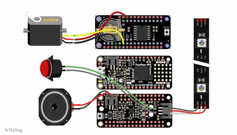
NeoPixel Strip – 30 LED (2 meters) (https://adafru.it/Duu)
     Servo Continuous Rotation (https://adafru.it/Dtv)
     16mm push button (https://adafru.it/CJg)
     3W 4Ohm Speaker (https://adafru.it/CVR)

Hardware & Supplies

     Neodymium Magnets Discs – D41 - 1/4" dia 1/16" thick (https://adafru.it/Dtw)
     Precision Ball Bearings 10x15x4mm (https://adafru.it/Dtx)
     Slotted Aluminum Extrusion 610mm (https://adafru.it/Dty)
     Slim T-Nuts (https://adafru.it/Dtz) or Oval T-Nuts (https://adafru.it/DtA)
     M4 x 8mm Button Hex Machine Screws (https://adafru.it/DtB)
     M3 x 12mm standoffs (https://adafru.it/Bke)
     M3 metric hex jam nuts (https://adafru.it/DtC)
     M3 x 8mm Flat head machine screws (https://adafru.it/DtD)
     M3 x 16mm button head machine screws (https://adafru.it/CVp)
     Black Nylon M2.5 Standoffs Kit (https://adafru.it/wsc)
     28AWG Silicone cover ribbon cable (https://adafru.it/CJj)
     pico blade speaker cable (https://adafru.it/CVi)
     3-pin JST cable (https://adafru.it/CVg)
     NITTO double-sided tape (https://adafru.it/zBn)
     Jumper Ring with Clasp

Prerequisite Guides
If you're new to Adafruit Feather M4 Express, CircuitPython or soldering, take a moment to walk through the following
guides to get you started.

     Adafruit Feather M4 Express (https://adafru.it/DtE)
     Welcome to Circuit Python (https://adafru.it/cpy-welcome)
     Adafruit NeoPixel Uber Guide (https://adafru.it/dhw)
     Adafruit Precision RTC FeatherWing (https://adafru.it/DtF)
     Adafruit's Guide to Excellent Soldering (https://adafru.it/CjY)

Going Further
The circuit, code and mechanics of this project could be applied to different themes. It's basically a motorized lamp
with sounds effects that can be triggered via some sort of input. Think of an On-Air sign or traffic signal that can
announce audible alerts. Make it an IoT project by connecting online – Custom triggers for the motor, lights and
sounds.

 © Adafruit Industries               https://learn.adafruit.com/new-years-eve-ball-drop                    Page 7 of 46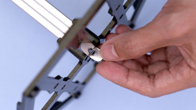
Circuit Diagram
Circuit Diagram
This provides a visual reference for wiring of the components. They aren't true to scale, just meant to be used as
reference. This diagrams was created using Fritzing software (https://adafru.it/oEP).

Adafruit Library for Fritzing
Use our Fritzing parts library to create circuit diagrams for your projects. Download the library or just grab the
individual parts. Get library and parts from GitHub Adafruit Fritzing Parts (https://adafru.it/AYZ).

Circuit
The Feather M4 Express, Prop-Maker Wing and Precision RTC FeatherWing are snap onto a Tripler FeatherWing. This
PCB features additional pinouts and power rails that make it easier to connect wires. The button and servo are wired to
the Tripler PCB via a JST PH 2-pin/3-pin connection for easy assembly.

Prop-Maker FeatherWing

      Speaker to speaker port
      NeoPixel Data In pin to NeoPixel port
      NeoPixel GND pin to NeoPixel port
      NeoPixel 5V pin to NeoPixel port
      Button to Switch Ground Pin
      Button to Switch Pin

Tripler FeatherWing

      GND from servo to ground pin
      Signal from servo to A1 pin
      Voltage from servo to USB pin

Powering
The Adafruit Feather M4 Express can be powered via USB. Use a micro USB cable and connect to a 5V USB battery

 © Adafruit Industries               https://learn.adafruit.com/new-years-eve-ball-drop                       Page 8 of 46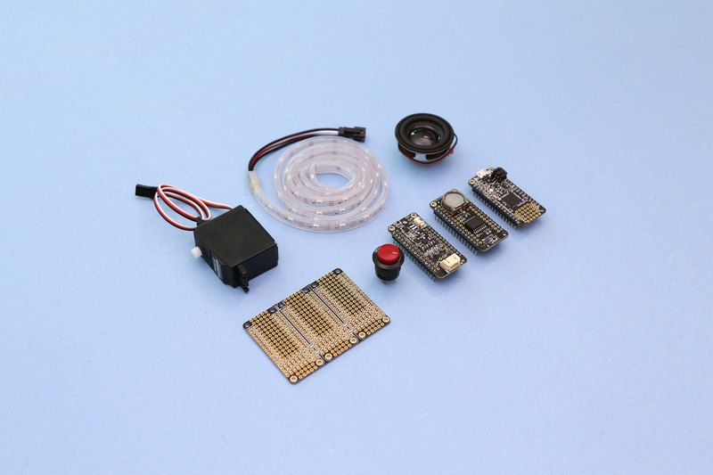
pack or wall adapter.

 © Adafruit Industries   https://learn.adafruit.com/new-years-eve-ball-drop   Page 9 of 46
Software

Setup Adafruit Feather M4 for CircuitPython
Your Adafruit Feather M4 should already come with CircuitPython but maybe there's a new version, or you overwrote
your board with Arduino code! In that case, see the below for how to reinstall or update CircuitPython. Otherwise you
can skip this and proceed with the build.

                                                     https://adafru.it/CVs
                                                      https://adafru.it/CVs

CircuitPython Libraries
Install the following Adafruit libraries for Circuit Python by downloading the latest bundle. Unzip the file and locate the
needed libraries. Drop the libraries into a folder named "lib" on the CIRCUITPY drive.

Required CircuitPython Libraries:

      adafruit_bus_device
      adafruit_ds3231
      adafruit_motor
      adafruit_register
      debouncer.py
      neopixel.mpy

Before continuing make sure your board's lib folder or root filesystem has the library files copied over.

                                                     https://adafru.it/uap
                                                      https://adafru.it/uap

Download code bundle
The full code listing is available here (https://adafru.it/DtK)

You can download all the project source code by clicking below, it even includes the WAV file!

                                                     https://adafru.it/DtK

 © Adafruit Industries                 https://learn.adafruit.com/new-years-eve-ball-drop                    Page 10 of 46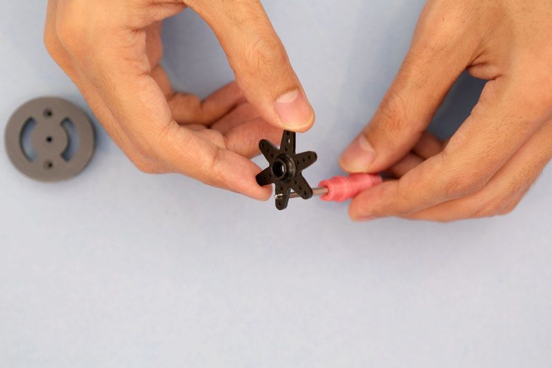
https://adafru.it/DtK

Summary
When the time is 11:59, the continuous rotation servo slowly turns and lowers the ball. A 10-second countdown audio
file plays over the speaker while neopixels cycle through colors. "Auld Lang Syne" plays after the countdown while
neopixels display a show of firework effects.

If you want a more in-depth explanation of how this project works, check out Dave Astel's guide on CircuitPython state
machines. (https://adafru.it/DtL) It goes into a lot more detail of how he got this code structured and working!

Audio Files
Two separate audio wave files are used. The main song file name is "Auld_Lang_Syne.wav" – This audo can be
changed, just make sure the code reflects any file name changes. The crowd cheering audio file name is
"countdown.wav" likewise, can be changed.

Original audio sources:

     Auld Lang Syne New Year's Eve
           https://commons.wikimedia.org/wiki/File:Auld_Lang_Syne_New_Year%27s_Eve.ogg (https://adafru.it/DtM)
     Countdown crowd audio sample

           https://freesound.org/people/FreqMan/sounds/88002/ (https://adafru.it/DtN)

Test/Reset Mode
A momentary pushbutton can be used to trigger the servo and run through the states. This is used to trip the ball drop
for on-demand testing.

     Single press will activate the countdown followed by song with fireworks.
     Press to pause while sequence is running. Press again to resume.
     2-second press and hold will activate reset mode turning servo to wind up ball with rope.

Setting The Time
The time must be set on line 87 – This sets up the initial time in the internal clock. Follow the comments above for year,
month, day, minute, etc. Use the test_trigger function on line 288 to adjust the trigger time – This is when the ball
drops.

For testing the RTC, we set the trigger time 10 seconds before the initial time to trip the ball drop shortly after powering
on the circuit.

Adjust the values in the code to reflect your desired trigger time.

 t = time.struct_time((2018,       12,    31,    23,   58,   55,      1,    -1,    -1))

 © Adafruit Industries               https://learn.adafruit.com/new-years-eve-ball-drop                     Page 11 of 46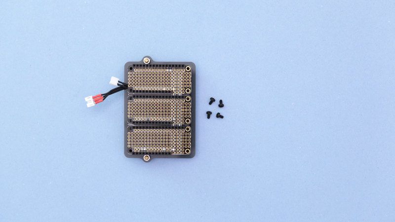
if test_trigger or (t.tm_mday == 31 and
     t.tm_mon == 12 and
     t.tm_hour == 23 and
     t.tm_min == 58 and
     t.tm_sec == 45):

Modify Parameters
Common parameters to tweak are the number of pixels, ball drop speed, and duration. Read the comments in the
code to see more.

 # Implementation dependant things to tweak
 NUM_PIXELS = 78               # number of neopixels in the striup
 DROP_THROTTLE = -0.03         # servo throttle during ball drop
 DROP_DURATION = 10.0         # how many seconds the ball takes to drop
 RAISE_THROTTLE = 0.1         # servo throttle while raising the ball
 FIREWORKS_DURATION = 30.0    # how many second the fireworks last

Upload The Code
Copy and paste the code below into a new text document (we recommend using Mu (https://adafru.it/ANO) as your
editor, which is designed for CircuitPython.). Save the file and name it as code.py

                                                https://adafru.it/ANO
                                                 https://adafru.it/ANO

Once the files has been uploaded to the drive, the board will automatically reboot and run the code.

       In order for the code to function properly, the FeatherWings must be connected to the Feather M4 via the
       Triper FeatherWing or similar.

 © Adafruit Industries             https://learn.adafruit.com/new-years-eve-ball-drop                  Page 12 of 46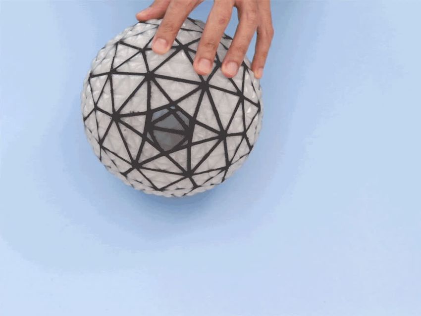
3D Printing
3D Printed Parts
Parts are designed to be 3D printed with FDM based machines. STL files are oriented to print "as is". Machines with
dual extrusion or single extrusion setups are listed below with parts name and description. Parts require tight
tolerances that might need adjusting slice setting. Reference the suggested settings below.
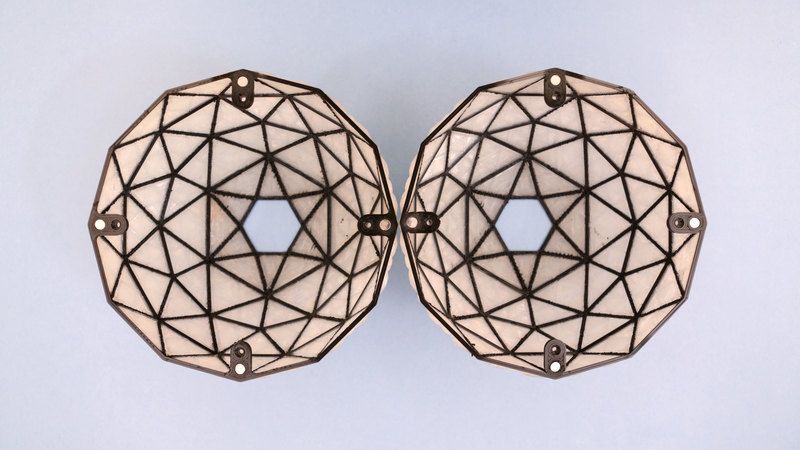
Domes Halves
The geodesic sphere is comprised of two 3D printed
domes. The dome can be 3d printed using a multi-
material tool head or a single extrusion 3d printer. The
dome models can be 3d printed without any support
material.
Build Requirement: 182mm (7in) x 82mmm (3in)
CURA Slicing
The multi-colored dome was slice using Ultimaker's
CURA 3.x for an Ultimaker S5 and 3. The model does
not require a prime tower or any additional support to
print properly. Parts A and B are assigned to extruder 1
and 2 with respects to the preloaded colored filament.
The B labeled model is indented for translucent filament.
Printing Times
© Adafruit Industries https://learn.adafruit.com/new-years-eve-ball-drop Page 13 of 46A tool head with larger diameter nozzle can dramatically speed up the printing time. Here's some time estimates
comparisons of printing the dome with a 0.4mm and 0.8mm nozzle (single and dual extruded). Note thicker layer
height. Another trick to reduce print time is to set infill to 0%.
Single Extruded Domes
17h 42m – 0.2 layer height 0.4mm nozzle
4h 51m – 0.4 layer height 0.8mm nozzle
Dual Extruded Domes
6h 37m - dual extruded dome - 0.4 layer height / 0.8mm nozzle
21h 38m – 0.2 layer height 0.4mm nozzle
Parts Assemblies
There are several parts in this build. Below are the subassemblies sectioned out with file names of each part. The
thumbnail gives a visual of the part.
https://adafru.it/DtQ
https://adafru.it/DtQ
Base Assembly
Most of the main components are mounted to the stand.
The speaker, button and triper featherwing mounting
plates are secured the stand using standoff and
machine screws. The base box covers the components
and snap fits onto the stand.
base-plate.stl
base-box.stl
button-plate.stl
tripler-mount.stl
© Adafruit Industries https://learn.adafruit.com/new-years-eve-ball-drop Page 14 of 46Servo Assembly
Parts for the servo mount. The tabs are used as spacers
in between the servo mounting tabs.
servo-mount.stl
servo-brace.stl
servo-hub.stl
servo-tab.stl
Idler Assembly
The spikes are super glued to the grooves on the side
of the idler.
idler-adapter.stl
idler-cap.stl
idler-pulley.stl
idler-spike.stl
idler-mount.stl
© Adafruit Industries https://learn.adafruit.com/new-years-eve-ball-drop Page 15 of 46Roller Assembly
This sub assembly will need to be 3d printed twice. Each
dome will need a roller assembly so make two sets.
dome-frame.stl
pixelcore.stl
roller-idler.stl
roller-plate.stl
roller-wheel.stl
Sphere Assembly
The domes are dual extruded in dark and translucent
material. Optionally, 3D print a unified version for a
single extruder.
geodesic-A.stl
geodesic-B.stl
geodesic-dome.stl
Tap Mounting Holes
I used a set of screw taps to create threads in the various mounting holes. This greatly improves fastening screws. of
the A mix of metric sizes are used here. M2.5 and M3 taps for the various mounts.
Design Source Files
The enclosure assembly was designed in Fusion 360. This can be downloaded in different formats like STEP, SAT and
more. Electronic components like the board, displays, connectors and more can be downloaded from our Fusion 360
CAD parts github repo (https://adafru.it/AW8).
© Adafruit Industries https://learn.adafruit.com/new-years-eve-ball-drop Page 16 of 46https://adafru.it/AW8
https://adafru.it/AW8
© Adafruit Industries https://learn.adafruit.com/new-years-eve-ball-drop Page 17 of 46FeatherWing Assembly
PCBs and Hardware
Gather the hardware needed to secure the Triper
FeatherWing to the PCB mounting plate. Solder the
headers to the Triper and Feather Wings if you haven't
already. Here's a quick list of screws used.
4x M2.5 x 5mm standoff
4x M2.5 hex nuts
4x M2.5 button head machine screws
3x M3 x 5mm standoff
3x M3 hex nuts
3x M3 x 5mm flat head machine screws
Install PCB Standoffs
Start by fastening the M2.5 nylon standoffs to the four mounting holes on the corners of the PCB mounting plate. Insert
and fasten hex nuts to the standoffs and then hand tighten.
Mounting Plate Standoffs
Install the three M3 standoffs onto the mounting plate. Insert them on the other side of the mount, so they are
protruding away from the M2.5 nylon standoffs. Fasten M3 hex nuts to secure the standoffs to the mounting plate.
Tripler FeatherWing
Place the Adafruit Tripler FeatherWing over the four nylon standoffs and line up the mounting holes. Insert and fasten
4x M2.5 x 5mm nylon screws to secure the PCB to the standoffs. Be cautious not to over tighten the nylon screws.
© Adafruit Industries https://learn.adafruit.com/new-years-eve-ball-drop Page 18 of 46Installing FeatherWings The mounting holes on the corners of the Triper FeatherWing are symmetrical, so it can be secured in reversed. (if needed). The Prop-Maker FeatherWing, M4 Express and Precision RTC FeatherWing can be installed onto the headers of the Adafruit Tripler FeatherWing. Just be sure to match up the rows of headers before snap fitting them on top. © Adafruit Industries https://learn.adafruit.com/new-years-eve-ball-drop Page 19 of 46
Speaker
Button
Speaker Button Parts
Gather the speaker, button, mounting plate and
hardware needed. The speaker will need a pico blade
cable (https://adafru.it/CVi) soldered to it. The
pushbutton uses a JST PH 2-pin (https://adafru.it/doS)
cable set.
3x M3 x 12mm standoffs
3x M3 x 5mm flat head machine screws
Install Standoffs
Start by fastening flat head screws into the three holes on the mounting plate. Insert and twist to fasten the standoffs
onto the threads of the three screws.
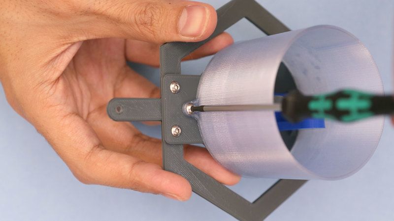
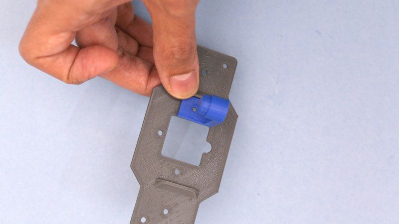
Install Speaker & Button
Remove the washer ring and hex nut from the button. Press fit the button into the 16mm hole on the mounting plate.
Insert and fasten the washer and hex nut back onto the button to secure onto the mounting plate. The speaker is
press fitted into the 40mm diameter hole – a square slit cutout allows the contact leads and wiring to pass through.
text
© Adafruit Industries https://learn.adafruit.com/new-years-eve-ball-drop Page 20 of 46Assembled Speaker Button Plate
And now we have our subassembly for the speaker and
button, yay!
© Adafruit Industries https://learn.adafruit.com/new-years-eve-ball-drop Page 21 of 46Servo Assembly
Servo Parts & Hardware
Gather the servo mounting parts and
hardware.
2x M3 x 16mm button head screws
2x M3 lock nuts
3x M3 x 5mm button head screws
3x M3 x 10mm standoffs
Install Mounting Tabs
Two additional tabs are used as spacers for securing the servo to the mounting bracket. Press them onto each tab and
fasten screws to secure them in place – Reference photo for best placement. Grab the servo brace and place it under
the mounting hole. Insert and fasten an M3 screw to secure the brace to the servo mounting bracket.
Secure Servo
Fit the body of the servo onto the mounting bracket so the tabs and holes are aligned and matching – Reference the
photo for best placement. Insert and fasten nylon lock nuts to the two 16mm long M3 screws.
Install Bracket Standoffs
Insert and install the remaining 2x M3 screws into the tabs on the sides of the servo bracket. Insert and twist to fasten
the M3 x 10mm standoffs to secure them to the bottom of the servo bracket.
© Adafruit Industries https://learn.adafruit.com/new-years-eve-ball-drop Page 22 of 46Servo Assembly We now have the servo assembly, nice! Remember that little extra brace? We'll need to adjust it a bit once we install it onto the stand, so don't over tighten it. © Adafruit Industries https://learn.adafruit.com/new-years-eve-ball-drop Page 23 of 46
Stand Assembly

                                                              Aluminum Extrusion Stand
                                                              Get the 2020 extrusion ready because we're going to
                                                              install it onto the stand. The stand is designed to press
                                                              fit onto the end of the extrusion – It features geometry
                                                              that slides into the t-slot of the profile.

Install Stand
Insert the extrusion into the stand by press fitting through the center. You can slide an oval t-nut through one of the t-
slots, insert through the bottom. These oval t-nuts are designed to fit the extrusion. Push in until screw hole matches
mounting hole on the stand. Insert and fasten an M4 screw – The screw thread needs to catch the t-nut, so make
adjustments as necessary. Fasten the screw tightly to secure the extrusion to the stand. The t-nut won't be visible once
installed.

Install Speaker Button Assembly
Grab the assembly and get it ready to fit onto the stand. The mounting holes on the stand might appear randomly
placed, so reference the photo for correct placement. Place the standoffs over the stand and line up the mounting
holes. Flip the assembly over and drive M3 flat head machine screws through the bottom of the stand to secure the
standoffs on the speaker assembly.

Install Tripler Assembly

 © Adafruit Industries              https://learn.adafruit.com/new-years-eve-ball-drop                      Page 24 of 46
Get the tripler ready to install. Place it over the stand and line up the standoffs with the mounting holes. Flip assembly
over and drive 3x M3 flat head machine through the bottom of the stand. Hold speaker button assembly in place while
fastening screws.
Install Servo Assembly
Grab the servo and place it on top of the stand. Orient the servo assembly so the drive shaft is positioned in-line with
the t-slot. The mounting holes should line up with the standoffs on the servo assembly. With the assembly positioned,
flip it over and drive the screws to secure in place.
Secure Servo Brace
Remember the extra brace we added to the servo
mount? Line it up with the remaining mounting hole on
the stand. Then, drive an M3 flat head screw through the
bottom of stand so it goes through the tab on the end of
the brace. To secure the brace to the stand, add a nylon
lock nut and tighten.
© Adafruit Industries https://learn.adafruit.com/new-years-eve-ball-drop Page 25 of 46Roller Assembly
Roller Hardware & Parts
Gather the parts and hardware for assembling the roller.
We'll need the following hardware:
2x precision ball bearings
6x M3 x 6mm button head metric screws
Install Bearing Pegs
The precision ball bearings are affixed to these cylindrical pegs. The pegs will need to be secured to the roller plate
using machine screws. Place the peg over the roller plate and line up the mounting holes. Whole holding peg in place,
insert and fasten machine screws to secure. Repeat process for second peg. The parts are symmetrical so orientation
can be in either direction.
Install Plate to Frame
Now we need to secure the roller plate to the dome frame. Place the roller plate over the frame and line up the four
mounting holes. Mounting holes are symmetrical and parts can be flipped over if needed. While holding parts together,
insert and fasten M3 x 6mm button head machine screws.
© Adafruit Industries https://learn.adafruit.com/new-years-eve-ball-drop Page 26 of 46Ball Bearing Wheels Grab the two precision ball bearings and press fit them into the roller wheels. The tolerances should be tight and snug fit. Insert the wheeled bearings onto the two pegs of the roller plate. Install Pixel Core The pixel core is to be secured onto the roller plate. This cylinder goes over the roller wheels. Place it over the assembly and line up the tabs with the mounting holes on the plate. Insert and fasten 2x M3 x 6mm button head machine screws. Test Rollers Now is a great time to test out the rollers with the 2020 t-slotted aluminum extrusion. Insert the roller assembly through the aluminum extrusion with the roller wheels inserting through the t-slots. These should roll freely along the railing. Make A Second Roller Assembly We'll need a second roller assembly to complete the build. The 2nd roller is exactly the same as the first one – The assembly is mostly composed of symmetrical parts so you just need to 3D print out the exact same parts, just twice. You will also need a second pair of hardware. © Adafruit Industries https://learn.adafruit.com/new-years-eve-ball-drop Page 27 of 46
NeoPixel Wiring
NeoPixel Planning
I suggest using a low-density NeoPixel strip (https://adafru.it/DtG). These contain 30 pixels, per meter of length. A 2-
meter long reel of NeoPixel strips will work best for providing the sphere with total coverage of glowy. Take the whole
strip and cut it on half so that you have two 30 pixel strips.

Solder Cable to NeoPixel Strips
These strips will need cables soldered to them. One of the strips will need both ends wired (The data in and data out
connections). I used JST PH 3-Pin connectors (https://adafru.it/CVg) with 28-AWG silicon covered stranded
wire (https://adafru.it/CVj) to create a 20in (50cm) long cable. This lengthy cable is connected to the strip that will act
as the very first neopixel in the chain. A second cable, 2in (5cm) long is connected to the end of the strip with the data
out connection. This second cable features a male JST PH 3-pin connector.

Top Halve NeoPixel Strip
The second neopixel strip only needs one end wired (data in). I used a female JST PH 3-pin connector, with a wire
length of 5cm. This cable plugs into the data out connections on the first neopixel strip.

3-Pin JST PH
It's important to match the colors of wires with connections. Follow this order: red colored wire connects to voltage
(5+), black wire to ground (GND) and white wire to data (DIN / DOUT).

 © Adafruit Industries               https://learn.adafruit.com/new-years-eve-ball-drop                      Page 28 of 46
PixelCore Assembly

                                                  Tape Pixel Core
                                                  The LED strips will need to be affixed to the pixel core. I
                                                  used double-sided NITTO tape to adhere the back of
                                                  the flexible PCB from the NeoPixel strips. I applied short
                                                  strips of tape across the cylinder in a staggered pattern.
                                                  I found NITTO tape has a strong hold and doesn't leave
                                                  behind residue.

                                                  Secured NeoPixel LED Strip
                                                  The placement of the LED strips needs to be
                                                  considered and planned. The top and bottom halves of
                                                  the geodesic sphere ought to have a linear flow – data
                                                  in flowing to data out. The assembly in this photo shows
                                                  the bottom half. The long cable connects to the very first
                                                  neopixel strip and will feed out the bottom of the
                                                  geodesic sphere. The strip wraps around the cover in a
                                                  clockwise direction.

                                                  NeoPixel Flow
                                                  The second LED strip is attached to the second pixel
                                                  core cover using more NITTO tape. Adhere the strip so
                                                  that it follows the same direction of data flow as the first
                                                  LED strip. Position the first pixel (with soldered cable)
                                                  near the bottom of the cover and wrap the rest around
                                                  the cylinder.

© Adafruit Industries   https://learn.adafruit.com/new-years-eve-ball-drop                      Page 29 of 46
Double NeoPixel Cores
Here are the two neopixel strips laid out in the proper
arrangement. The beginning of the chain starts on the
left with the first neopixel connecting to the longer
cable. The last pixel on that strip connects to the first
pixel on the second core. Note the data flows in a
consistent direction across both strips. (The core on the
right side actually has a medium-density neopixel strip
which was left over from prototyping).
Take this moment to adjust the arrangement of the
neopixels. Check and ensure the strips are adhered to
the cylinder. Are the connectors able to plugin across
the two strips?
Pixel Double Stack
Here's the two pixel cored stacked on top of each other,
which is how they will be arranged once secured inside
the geodesic sphere.
© Adafruit Industries https://learn.adafruit.com/new-years-eve-ball-drop Page 30 of 46Dome Assembly
Install Magnets
The domes feature four mounting tabs with cavities. These are designed to fit ne (https://adafru.it/Dtw)odymium
magnets discs (https://adafru.it/Dtw) – (D41 - 1/4" dia 1/16" thick). These can be super glued to the tabs but it's super
important the polarities match across the two domes. Marking the north and south poles are a good method. I kept
track of the polarities while placing by hand holding a stack – Use your preferred method!
Install Dome Framing
The pixel core roller assemblies are secured inside the
domes. Place one of the cores inside one of the domes
and line up the mounting tabs with the holes on the
framing. Insert and fasten M3 x 10mm flat head machine
screws through the tabs. Hold the framing in place while
fastening the screws. Repeat this process for the
remaining tabs and proceed to setup the second dome.
© Adafruit Industries https://learn.adafruit.com/new-years-eve-ball-drop Page 31 of 46Glowy Domes
With both domes setup with the pixel core assembles,
it's a good idea to test out the neopixel strips. To do this,
I plugged in the first strip to the Prop-Maker
FeatherWing and ran a neopixel
strandtest (https://adafru.it/CYZ). This way we can see if
there's any dead pixels (fingers crossed) and if our pixel
arrangement is how we want it. I must have rearranged
the two at least a dozen times, so don't be too upset if
you need to take it apart ;-)
Glowing Sphere!
And here it is! Behold, a glowing geodesic sphere.
Before closing up the two domes, you may need to tuck
in some of the wiring – Plenty of room near the sides to
stuff! You'll want to throughly expect the edges and
make sure none of the wires are kinked.
© Adafruit Industries https://learn.adafruit.com/new-years-eve-ball-drop Page 32 of 46Rope Assembly Rope Setup The ball is lowered with a long piece of rope/twine. The stuff I used was made from hemp, purchased from the craft store. Yoyo string is a great option. The string should be roughly 47-inches (119cm) in length – This will cover most of the 610mm long aluminum extrusion. Tip: I used a drop of super glue to seal the tips, this prevents the strands from fraying. Tie Rope End A jump ring is tied to one end of the string. Any 6-10mm diameter jump rings will do. These are commonly used for jewelry crafting. © Adafruit Industries https://learn.adafruit.com/new-years-eve-ball-drop Page 33 of 46
Drive Hub Assembly

                                                             Drive Hub Parts
                                                             Time to assemble the drive hub. Use the star shaped
                                                             servo horn that is included with the continuous rotation
                                                             servo. The two screws used to servo the horn to the
                                                             drive hub are M2.5 x 10mm flat head machine screws. A
                                                             single M3 hex nut is used to anchor the string.

Screw Tap Holes
Depending on the size of the screws, you'll want to tap threads into the mounting holes. Place the servo horn over the
drive hub and line up the mounting holes – This gives a visual reference of which holes to use.

Secure Hub to Horn
With the holes properly tapped and threaded, hold the horn and hub together while driving the screws through the
mounting holes. I used flat head machine screws because the screw heads can be flush.

 © Adafruit Industries             https://learn.adafruit.com/new-years-eve-ball-drop                    Page 34 of 46
Center Screw
The continuous servo comes with a few screws used for
mounting. I picked one of the black ones and inserted it
through the center hole of the drive hub. This will be
used to serve the drive hub to the shaft of the servo.
Install Rope to Hub
The drive hub has a 3mm diameter hole in the grove. It's for anchoring the rope to the drive hub. Insert the end of the
rope and pull it through. Tie the end of the rope to an M3 hex nut (or whatever is similar) so that the rope gets
anchored.
Wind Up Hub
Give the rope a firm tug to ensure it's properly anchored to the drive hub. The geodesic sphere weighs ~1lbs (10 oz) so
it needs to be able to manage that much. The groove in the drive hub allows the rope to wind up a few times before
reaching capacity.
© Adafruit Industries https://learn.adafruit.com/new-years-eve-ball-drop Page 35 of 46Install Clasp
The other end of the string has the jumper ring. Go
ahead and install a clasp – This will make it easier to clip
it onto the roller assembly inside the geodesic sphere.
Install Hub to Servo
Grab the stand assembly and position the drive hub over the servo. Press fit the servo horn onto the shaft of the
continuous rotation servo. Then, fasten the center mounting screw until tight – The hub will begin to rotate when its
fully tightened. I suggest installing the hub with the rope outside the groove.
Install Stand Cover
OK, now it's time to fit the box over the stand. To do this, you'll need to thread the rope through the center cutout in
the center. Use the photo for reference. The cover will have to go over the 2020 extrusion. Insert the cover through
the extrusion with it going through the center cutout (similar to the rope). Rotate the cover so the cutouts line up with
the components. The cover is designed to snap fit onto the stand. Inspect the edges for any gaps or hanging wires,
tuck them in if necessary.
© Adafruit Industries https://learn.adafruit.com/new-years-eve-ball-drop Page 36 of 46The rope should be accessible outside the cover with the clasp affixed to the end. © Adafruit Industries https://learn.adafruit.com/new-years-eve-ball-drop Page 37 of 46
Dome Rail Assembly

                                                                Thread The Rope
                                                                Grab the rope with the clasp on the end and thread it
                                                                through the halve of the dome with the longer cable.
                                                                Pass it through the center bottom opening and grab the
                                                                end so the rope is through the dome. Ensure the rope
                                                                does not catch any of the rollers.

Looping Thread
Use the clasp to clip onto the mounting near the center of the square opening. Keep the rope on hand and begin to
pull to gain a moderate amount of slack. While holding onto the rope, form a loop. Grab the other halve of the sphere
and begin to thread the loop through the center. The rope needs to be a loop in order for the pulley mechanism to
function properly. Insert the rope loop through the square opening on the roller plate. Pass it through the core and out
the end of the dome while maintaining the loop. Pull the rest of the slack through so the rope is taught.

Bring the two halves together and match up the orientations so they're mirrors of each other. When the tabs mate the
magnets to snap the two halves shut. The magnets has enough hold to keep them secured. Keep the string on hand.

Install Ball to Railing
Bring the ball over to the aluminum extrusion. Orient and position the ball so the rope can function with a pulley
relative to the position of the drive hub.

Insert the extrusion through the end of the ball (the side with the long cable). Fit the roller wheels onto the t-slots of
the extrusion. Slide the rest of the sphere through the extrusion.

Temporarily wrap the rope loop wrap over the tip of the extrusion.

Position the sphere so the rope becomes taught.

 © Adafruit Industries                https://learn.adafruit.com/new-years-eve-ball-drop                      Page 38 of 46
Drive Hub Rope T Slots
The rope passes straight through the t-slots on two sides of the extrusion. Rotate the drive hub to wind up the rope.
Clockwise rotation if your assembly matches orientation in the photo. With the rope taught, the rope should straight out
and follow the t-slots. The sphere should freely slide along the extrusion. Keep the rope taught when positioning the
sphere.
Assembly Side-Notes
This is admittedly the trickiest part of the assembly. I had issues figuring out the most efficient procedure for easy
assembly so it may feel awkward. My advice is to have the pieces near by and do things slowly. Keep the rope at hand
so it doesn't fall into the roller assembly – Fishing it out with tweezers can be helpful. Don't twist the sphere
excessively or the bearing wheels could pop off.
Assembly Side-Notes
This is admittedly the trickiest part of the assembly. I
had issues figuring out the most efficient procedure for
easy assembly so it may feel awkward. My advice is to
have the pieces near by and do things slowly. Keep the
rope at hand so it doesn't fall into the roller assembly –
Fishing it out with tweezers can be helpful. Don't twist
the sphere excessively or the bearing wheels could pop
off.
© Adafruit Industries https://learn.adafruit.com/new-years-eve-ball-drop Page 39 of 46© Adafruit Industries https://learn.adafruit.com/new-years-eve-ball-drop Page 40 of 46
Idler Assembly
Idler Bearing
The idler can be bedazzled with a 6mm diameter rhinestone and 3d printed spikes. The rhinestone is press fitted into
the cavity in the center of the pillar. I super glued the spikes to the groves on the side of the idler. The idler uses a
precision ball bearing and 3d printed wheel to function as a pulley system for the rope.

Install Wheel Ball Bearing
Press fit the wheel over the ball bearing (size 10 x 15 x 4mm). Place the ball bearing over the pillar in the center of the
idler. Press the bearing through the peg to seat the wheel to the idler. It should rotate and spin freely.

Install Idler Adapter
The idler needs an adapter piece in order to mount it to the aluminum extrusion. Place the idler over the adapter and
line up the mounting holes. Use two M3 x 8mm long button head machine screws to join the two parts. Hold the parts
together and drive the screws through the mounting holes. Fasten and fully tightened.

 © Adafruit Industries               https://learn.adafruit.com/new-years-eve-ball-drop                      Page 41 of 46
Install Idler Cap
The idler adapter is secured to a mounting bit that is designed to fit over the aluminum extrusion. Use two M3 x 6mm
screws to join the adapter to the cap. Place the cap under the idler and line up the two mounting holes. Hold the parts
together and drive the screws through the mounting holes. Fasten and fully tighten.

Install Oval T-Nut Screw
The cap can be secured to the aluminum extrusion using an oval t-slut and M4 screw. These are designed to slide into
the t-slots. Insert and fasten an M4 screw through the mounting hole on the side of the cap. Twist until thread is half
way through – Insert oval t-nut and fasten.

 © Adafruit Industries              https://learn.adafruit.com/new-years-eve-ball-drop                   Page 42 of 46
Idler Assembly
                                                  And now we have our pulley assembly ready to install.
                                                  The bottom of part the idler is called the cap because it
                                                  will be fitted over the aluminum extrusion essentially
                                                  capping it off.

© Adafruit Industries   https://learn.adafruit.com/new-years-eve-ball-drop                    Page 43 of 46
Idler Rail Assembly Install Rope Idler Grab the pulley assembly and begin to work the rope over the wheel bearing. Pinch the rope with a finger nail into the gap between the wheel and idler. Start to rotate the wheel so the rope is guided onto the groove. Fit the rope onto the wheel and place the idler assembly over the aluminum extrusion. The idler cap is designed to fit into the profile of the extrusion. Make sure the orientation idler matches with the rope and drive hub. Secure Idler to Rail Press the idler onto the tip of the extrusion so it caps it off. If the idler doesn't freely slide in, the oval t-nuts might be to be adjusted so they can fit through the t-slots on the extrusion. Idler Adjustments Adjust the screw and unfasten to loosen the t-nut if needed. The t-nut is not 100% required - The pulley can function without it, just won't be as secure with it installed. Once it's properly installed, the screw and t-nut can be tightened to secure the idler to the extrusion. © Adafruit Industries https://learn.adafruit.com/new-years-eve-ball-drop Page 44 of 46
Testing The idler
                                                  Check the rope is properly installed onto the wheel
                                                  bearing and idler secured to the extrusion. The whole
                                                  build can be propped upright and tested. The linear
                                                  motion of the sphere should be tested along with the
                                                  idler. Make any adjustments as necessary.

© Adafruit Industries   https://learn.adafruit.com/new-years-eve-ball-drop                    Page 45 of 46
© Adafruit Industries Last Updated: 2019-09-20 05:24:27 PM UTC Page 46 of 46
You can also read