NORTHWEST FALL/WINTER - North American Society for Trenchless ...
←
→
Page content transcription
If your browser does not render page correctly, please read the page content below

2021 | NORTHWEST                                                 FALL/WINTER

                                          THE OFFICIAL PUBLICATION OF THE NORTHWEST CHAPTER OF
                                        THE NORTH AMERICAN SOCIETY FOR TRENCHLESS TECHNOLOGY
PM #40065075

                    DESIGNED & CONSTRUCTED MICROTUNNEL FOR DOWNTOWN CALGARY
ANY SIZE. ANY LENGTH.
ANYWHERE.
NovaForm™ PVC Liner                                                           ADVANTAGES

Styrene Free Structural Liner for Sewers and Culverts
                                                                              Flexible, Durable
The need for a durable and cost-efficient pipe rehabilitation solution          and Reliable
has never been more paramount. The engineers at IPEX recognized           Time and Cost Savings
this need and have responded with NovaForm™ PVC Liner, a product
                                                                            Limits Environmental
that brings the lasting benefits of factory-made PVC pipe to the                 Disruptions
North American trenchless pipe rehabilitation industry.
                                                                         Available in Sizes 6” to 30”

To learn more, call or visit us at:                                          MUNICIPAL
1-866-473-9572           | i p ex n a .c o m                                  SYSTEMS
Infrastructure is Es
                                                   2021 | NORTHWEST

     NASTT-NW
 BOARD OF DIRECTORS
                 CHAIR
             BEN CAMPBELL
             Neptune Coring
                                                                            THE OFFICIAL PUBLICATION OF THE NORTHWEST CHAPTER OF
               VICE CHAIR
                                                                          THE NORTH AMERICAN SOCIETY FOR TRENCHLESS TECHNOLOGY
           SHANE COOPER
     Uni-Jet Industrial Pipe Services                                                                                                                                          A P R I L 1 0-1
             PAST CHAIR
            GREG TIPPETT
                                                   IN THIS ISSUE:

                                                                                                                                      NASTT 2022 N
         Stantec Consulting Ltd.
              TREASURER
          KEITH MOGGACH
         Royal Building Products
               DIRECTOR
               ALI BAYAT
           University of Alberta
                                                                                                                                                                                NODIGSHO
                                                                                    9                                                                                              19
               DIRECTOR
              SAM WILSON
                CCI Inc.
              DIRECTOR
           GEORGE BONTUS                           7   NO-DIG NORTH – VANCOUVER, BC       DEPARTMENTS:
           Aegion Corporation
                                                   9   NO-DIG SHOW 2022
                                                                                          MESSAGE FROM THE
               DIRECTOR                                IN MINNEAPOLIS
              CHAOSHI HU                                                                  MAGAZINE COMMITTEE..................... 6
                EPCOR                              11 CALL FOR MAGAZINE
               DIRECTOR                                NETWORKING
                                                       SUBMISSIONS EVENTS                 MESSAGE FROM NASTT...................... 8
            MUSTAFA YULEK
          TC Energy Corporation
                                                   13 NEW INDEX FOR DETERMINATION         ADVERTISER PRODUCT
                                                      OF CLOGGING POTENTIAL               & SERVICE CENTRE............................ 30
              DIRECTOR                                BASED ON A MIXING TEST
          KEITH KINGSBURY
         Associated Engineering                    19 CASE STUDY: THE DESIGNED AND
                                                      CONSTRUCTED MICROTUNNEL
       MAGAZINE COMMITTEE
          CARLIE PITTMAN                              FOR THE DOWNTOWN CALGARY
        Associated Engineering                        TRANSMISSION REINFORCEMENT
                                                      PROJECT
                                                   27 MUNICIPAL & PUBLIC UTILITY
                                                      SCHOLARSHIP PROGRAM
                                                                                                           2021 | NORTHWEST                                                 FALL/WINTER

www.kelman.ca
Managing Editor: Monique Doyle
Design/Layout: Dani Goulet
Marketing Manager: Chad Morrison
                                                         150+  TECHNICAL
                                                                 US ONLINEEDUCATION SESSIONS
                                                                                                                                      THE OFFICIAL PUBLICATION OF THE NORTHWEST CHAPTER OF
                                                                                                                                    THE NORTH AMERICAN SOCIETY FOR TRENCHLESS TECHNOLOGY

Advertising Coordinator: Stefanie Hagidiakow
                                                            VIEW
Return undeliverable Canadian addresses to:
lauren@kelman.ca                                             NASTT-NW.COM
Publication Mail Agreement #40065075
©2021 Craig Kelman & Associates Ltd.
All rights reserved. The contents of this
publication, which does not necessarily reflect
the opinion of the publisher or the association,
may not be reproduced by any means, in
whole or in part, without the prior written
consent of the Northwest Chapter of the North
American Society for Trenchless Technology.
                                                                                            PM #40065075

                                                                                                                DESIGNED & CONSTRUCTED MICROTUNNEL FOR DOWNTOWN CALGARY

                                                                                            ON THE COVER: Winter sunrise over downtown
                                                                                            Calgary. | dreamstime.com

                                                                                                                                                     NASTT-NW.COM | 5
MESSAGE FROM THE MAGAZINE COMMITTEE

   SEE YOU AT NO-DIG NORTH!

     Vancouver Convention Centre, Downtown Vancouver, BC

   W
             elcome to the Fall/Winter issue of        Also in this issue, we put the          Coming Up
             the Northwest Trenchless Journal,     spotlight on a case study about the         The Chapter magazine is published twice
             the official publication for          designed and constructed microtunnel        a year. The next issue of the Northwest
   members of the NASTT-NW Chapter. The            for the downtown Calgary transmission       Trenchless Journal is scheduled for
   big news in this issue is the No-Dig North      reinforcement project. This No-Dig 2021     distribution in the spring of 2022. It will
   event coming up in November. For more           case study begins on page 19.               include the Project of the Year winners, and
   information and to register to attend, please                                               the NW Chapter’s 2022 Buyers’ Guide.
   visit www.nodignorth.ca. We hope you can        Find Us Online                                  We are looking for relevant, regional
   join us in Vancouver, BC this year!             Remember to join the Northwest Chapter      feature content to share with members.
                                                   on LinkedIn, at www.linkedin.com/           Please contact Carlie Pittman at
   In This Issue                                   groups/4430433.                             pittmanc@ae.ca by April 3, 2022 for
   In this issue of the magazine, we look at a         You can also find the most recent       more information and to let us know if
   new index for determining clogging potential    issue of the Northwest Trenchless Journal   you have an article or paper you would
   when using tunnel boring machines. You can      online at https://nastt.org/resources/      like to contribute to the next issue of
   find this article on pages 13–15.               regional-chapter-magazines.                 this publication.

6 | NASTT-NW JOURNAL |     Fall/Winter 2021
                                                                                                                  BACK TO CONTENTS
NASTT-NW.COM | 7
BACK TO CONTENTS
MESSAGE FROM NASTT

                                 INNOVATION & RECOVERY
                                 IN THE TRENCHLESS INDUSTRY

   H
            ats off to NASTT and the                 date for what we expect to be a record                     for the in-person 2021 No-Dig North
            Board of Directors for making            level of attendees.                                        at the Vancouver Convention Centre in
            the decision to host an in-                  The No-Dig Show in Orlando was                         Vancouver, British Columbia on November
   person and virtual No-Dig Show in                 a wonderful opportunity to get back to                     8 to 10. The show will consist of two
   Orlando this past March. The in-person            normal and reconnect with our trenchless                   days of technical paper presentations
   conference was well attended with safe            colleagues. Now that things are beginning                  and industry exhibits in the trenchless
   networking and educational events.                to safely re-open throughout North                         technology field. Pre-event Good Practices
   Both the No-Dig Planning Committee                America, we are excited to see the No-Dig                  Courses will also be available to attend
   and the No-Dig Development                        North Show and regional conferences                        on Monday, November 8, followed by an
   Committee are hard at work to bring               scheduled to take place in the last quarter of             opening reception for all attendees.
   you exciting new networking events in             2021. Our Canadian partners have not been                      Many of the other regional chapters
   Minneapolis in April 2022. Make sure              able to participate in many events over the                have finalized their conference program/
   to mark your calendars and save the               last two years. There is much anticipation                 events for this year. There is a lot of
                                                                                                                excitement around the South Central and
                                                                                                                Northeast Chapter Conferences being held
       “In many cases these regional                                                                            in Sugar Land, TX and West Point, NY. In
     conferences are the first exposure                                                                         many cases these regional conferences are
                                                                                                                the first exposure to trenchless technology.
         to trenchless technology.”                                                                             The regional chapters are the grassroots of
                                                                                                                this society and what continues to grow
                                                                                                                trenchless technology at a local level.
                                                                                                                    NASTT Board of Directors has recently
                                                                                                                published the Strategic Plan 2021–2023
      1-866-976-2626                              www.ivisconstructioninc.com                                   which identifies the importance of our
                                                                                                                committees. The growth and leadership
                                                                                                                within these committees have allowed
                                                                                                                industry experts to work together for the
                                                                                                                common good of the trenchless industry. If
                                                                                                                you want to represent a part of trenchless
                                                                                                                technology, then I encourage you to get
                                                                                                                involved with NASTT committees or at
                                                                                                                the regional level and reap the benefits.
                                                                                                                Contact NASTT if you are interested in
      The Right People, The Right Equipment, The Right Choice                                                   a committee. Specifically, our Students,
                                                                                                                Education, and Publications committees
                  Servicing the Underground Infrastructure Since 1996                                           are very active working on the next
                                                                                                                webinar/training documents.
     • Secondary Utility Locates/GPR              • Hydro excavating utilities, piles, trenching                    It is an exciting time in the trenchless
     • High pressure flushing/vacuum               • High Rail Unit for hydrovac, flushing, vacuum                industry, and we are leading the way in
     • CCTV (camera) inspections of sewer lines   • Relining of sewer lines, storm lines, laterals, T-liners,   training, education, and research. There
     • Lift Stations-maintenance & refurbishing     manholes and lift stations and potable water lines
                                                                                                                may be uncertainty in our world, but one
                                                                                                                thing we know for sure, Infrastructure
             Residential • Commercial • Municipalities • Industrial                                             is Essential. The trenchless industry is
                                                                                                                strong and resilient, and here to stay!

8 | NASTT-NW JOURNAL |         Fall/Winter 2021
                                                                                                                                  BACK TO CONTENTS
Infrastructure is Essential.
                                      A P R I L 1 0-1 4, 2 0 2 2

                            NASTT 2022 No-Dig Show
                       Minneapolis Convention Center | Minneapolis, Minnesota

                                      N O D I G S H O W.C O M

NETWORKING EVENTS

 150+ TECHNICAL EDUCATION SESSIONS                      EXHIBIT HALL
Great ideas
are just below
the surface

      Design with community in mind | stantec.com/trenchless
Call for
Submissions
If you would like to submit your project
paper or other content and photos for an
upcoming issue of this Northwest Chapter
magazine, please contact Carlie Pittman,
Magazine Committee Chair, at
pittmanc@ae.ca.
Editorial submissions for the
Northwest Trenchless Journal are
welcome and due for our next
publication by April 4, 2022.
experienced in all types and sizes of crossings
Environmental Sensitive Area Crossings
Rivers | Creeks | Ravines
certificate of recognition
latest technology in navigation systems
committed to safety and to our environment
equipped with 110,000 lbs to 440,000 lbs capacity drills
www.precisecrossings.com
Spruce Grove, Alberta | P. (780) 962.6882 | Toll Free. (866) 962.6882
BACK TO CONTENTS NASTT-NW.COM | 11Celebrating 75 years of Engineering Excellence
Associated Engineering is celebrating our 75th anniversary! We are very proud of our long history as an
employee-owned, Canadian consulting firm, ranked as one of Trenchless Technology Magazine’s Top 50
trenchless design firms since 2013.
Specializing in trenchless design and construction, we provide communities with sustainable and resilient
solutions. Our expertise includes horizontal directional drilling, micro-tunnelling, slip-lining, direct pipe,
cased crossings, and pipe rehabilitation technologies.
www.ae.ca
Horizontal Directional Drill • Direct Pipe
Microtunnel • Auger Bore • Pipe Ram
Trenchless Engineering Consultants
Trenchless Project Management
Crossing Planning & Investigations
Geotechnical Investigations
Regulatory & Environmental Management
Trenchless Engineering and Design
Construction Tendering
Crossing Management
UAV Monitoring
On-Site Trenchless Inspection
Unit 9, 4948 – 126 Avenue S.E., Calgary, Alberta
info@bluefoxengineering.ca | 587-997-6080
12 | NASTT-NW JOURNAL | Fall/Winter 2021 BACK TO CONTENTSNew Index for Determination of
Clogging Potential Based on a Mixing Test
Background a TBM face – have benefits over other beater was then pulled out of the sample
Clogging can be a major problem for approaches, since they are dynamic systems and weighed. Inevitably, some of the
projects conducted using earth pressure and involve shear forces. sample remained stuck on the beaker.
balance tunnel boring machines (TBMs), This current work focused on In previous studies, the stickiness ratio,
especially for fine cohesive soils with assessing clogging potential based on a λ, i.e., the ratio of the mass of material
moisture content in the middle range. simple mixing test. A new index was also stuck to the beater (GMT) to the total sample
While geotechnical testing is standard for introduced to improve reproducibility of mass (GTOT) has been used as the index for
tunnelling projects, testing done in advance the results. a mixing test (Zumsteg and Puzrin, 2012).
of the project is limited to the borehole or However, since the amount of sample stuck
sampling sites. For in-progress projects, Method to the beater depends on the surface area –
onsite clogging potential tests using simple Building on mixing tests previously i.e., the contact area between the metal
equipment can be used to complement described in the literature (Zumsteg beater surface and the sample – the index
existing geotechnical information and and Puzrin, 2012; Kang et al., 2018), M/A, or mass of soil stuck to the beater (M)
mitigate the risk of clogging. portable, readily available equipment per unit area covered by the sample (A),
There are many factors to consider (a Hobart mixer and beaters of various was investigated in this work. Although
when developing a simplified test model shapes) was used to refine an existing the same sample mass was generally used
to accurately assess clogging potential. test method and gain insight into the across the different mixtures, the distance
These include the inherent tendency of the clogging potential. To simulate soils with that the sample extended up the beater (d)
soil to stick to itself (cohesion), and the a range of properties, mixtures of kaolin varied. The beater area (A) was determined
interaction between the soil and a surface and bentonite (ranging from pure kaolin using a method based on a three-
(adhesion). Analytical approaches such as to 10%, 30%, and up to 90% bentonite, dimensional computer model of the beater
measurements of adhesive and cohesive indicated by M10, M30, etc.) were used for and measurement of d.
forces are attractive in terms of simplicity test samples. Atterberg tests were done Mixing test results were mapped onto
and ease of application. However, they do to determine the plastic limit and liquid the soil classification chart developed by
not fully capture the complex, dynamic limit for each of the mixtures. Hollman and Thewes (2013), another
nature of the interactions between the To perform the mixing test, bentonite tool proposed to assess clogging potential
ground and the cutter face. Since it is and kaolin were mixed (as dry powders) based on plastic and liquid limits and
impractical to replicate the motion of a in the appropriate ratios. Then, a water content. A sensitivity analysis was
TBM in a laboratory setting at full scale, predetermined volume of distilled water – also conducted on sample mass and
compromise is necessary. Physical methods enough to give the targeted moisture beater shape to determine whether these
such as mixing tests – while they do not content – was added to the sample while parameters influenced the mass-to-surface-
fully capture the motion of a cutter at mixing for a set time. After mixing, the area ratio (M/A).
BACK TO CONTENTS NASTT-NW.COM | 13New Index for Determination of Clogging Potential Based on a Mixing Test
60
M10
M30
50 M50
M70
M90
40
M/A (kg/m2)
30
20
10
0
0.0 0.2 0.4 0.6 0.8 1.0 1.2
Consistency Index (IC)
Figure 1. Mass-to-surface-area ratio vs. consistency index.
Results and the beater size and geometry. A for beater size indicated that the mass-to-
The mass-to-surface-area ratio (M/A) peaked sensitivity analysis was conducted to surface-area ratio showed less variation
when the consistency index was between validate the results and check whether than the stickiness index for a series of
0.5 to 0.6 for each sample, as shown in M/A was independent of these factors. mixing tests conducted with different
Figure 1. Each data point represents For sample mass, the test was repeated beater sizes.
three replicate measurements. The peaks for four different masses (0.5 kg, 1 kg,
correspond to the region of high clogging in 1.5 kg and 2 kg) using mixture M50 (50% Conclusions
the empirical clogging diagram proposed by bentonite and 50% kaolin). For the lowest Based on these results, it was
Hollman and Thewes (2013), as indicated sample mass (0.5 kg) about one-third demonstrated that a simple mixing test
in Figure 2(a). The new index M/A of the beater was in contact with the can be used to indicate the clogging
increases with consistency index, reaches sample, and for the highest mass tested potential by analyzing the ratio of mass
a peak, and then declines, as expected. It (2 kg), the beater was completely covered of sample remaining on the beater to
was also noted that more reproducible test by the sample. Based on the results (not surface area (M/A). The index M/A
results were obtained using M/A compared shown), it was determined that M/A was allowed the clogging potential to be
to the stickiness ratio (λ). less sensitive to sample mass than the assessed quantitatively and gave more
Several factors could influence the stickiness index for consistency indices reliable results than the stickiness ratio.
test results, including the mass of sample above 0.4. A similar sensitivity analysis The mixing test based on the proposed
14 | NASTT-NW JOURNAL | Fall/Winter 2021 BACK TO CONTENTSNew Index for Determination of Clogging Potential Based on a Mixing Test
index (M/A) has several advantages over
60 This study Kang (2018) earlier methods proposed for determining
clogging potential. First, it is quicker
and simpler to perform this procedure
50
than to determine Atterberg limits
and water content of soil samples (as
40 HIGH CLOGGING required to use the qualitative diagram
proposed by Hollman and Thewes
M/A (kg/m2)
[2013]). Furthermore, the apparatus used
30 in the testing is easily portable and the
testing can be done on site. The results
MEDIUM
CLOGGING of this proposed method can be used to
20 complement geotechnical tests conducted
in advance of tunnelling projects and
10 LOW CLOGGING mitigate clogging risks.
ACKNOWLEDGEMENTS
0 This article gives an overview of research
0.0 0.2 0.4 0.6 0.8 1.0 1.2 conducted by Yang Zhou, MSc and Chao
Consistency Index Kang, PhD (University of Northern British
Columbia). Thank you to Lana Gutwin of
the Consortium of Engineered Trenchless
60 Technologies (CETT) at the University of
Alberta for her assistance in the preparation
of this article.
50
REFERENCES
Hollmann, F. S., Thewes, M. (2013)
40 “Assessment method for clay
clogging and disintegration of fines
M/A (kg/m2)
in mechanised tunnelling,” Tunnelling
30 and Underground Space Technology, 37,
96–106.
Kang, C., Yi, Y., Bayat, A. (2018)
20 “Performance evaluation of TBM
clogging potential for plain and
conditioning soil using a newly
10 developed laboratory apparatus,”
International Journal of Geotechnical
Engineering, 6362, 1–10.
0 Zhou, Y., Kang, C., Bayat, A. (2021) “The
Little Medium High Impact of Beater Shape in Mixing Test
to Determine Clogging Potential,”
Figure 2. (a) Classification of clogging potential based on mass-to-surface-area ratio. Green indicates little Journal of Testing and Evaluation,
clogging, yellow indicates medium clogging, and red indicates high clogging. (b) Statistical analysis of the same manuscript accepted.
data, with x indicating the median, and the line indicating the average. Zumsteg, R., Puzrin, A. M. (2012)
Figure 2(b) shows the statistical distribution of M/A across the various samples (for two data sets). Based on these “Stickiness and adhesion of conditioned
results, samples with values of M/A below 20 have little clogging potential. Values of M/A from 20 to 30 indicate clay pastes,” Tunnelling and Underground
medium clogging. A value of M/A above 30 indicates high clogging. Space Technology, 31, 86–96.
BACK TO CONTENTS NASTT-NW.COM | 15GUIDED
AUGER BORING
VS.
GUIDED
PIPE RAMMING
By: Jason Holden, Vice President, CRO
One of the most common trenchless
applications in North America is the
underground horizontal installation of
steel casing for utility crossings under
roads, railroads, rivers, and other
sensitive structures that do not allow
have allowed a wider range of ground
open-cut construction. Steel casing is
conditions including non-displaceable
often used as an encasement to protect
ground and soft rock. Typical accuracy
the product pipe from damage while
techniques and the tooling variations of installation is +/- 1 inch from design
supporting the bearing loads applied
available may help reduce future project grade and +/- 3 inches from the design
from the earth and structures located
risks, reduce overall costs, and increase alignment at any location with proper
above the ground. Several trenchless
productivity. equipment set-up. Hybrid setups are
techniques exist to install steel casing,
Akkerman GBM systems provide also being implemented with pneumatic
however the most widely used and often
critical line and grade accuracy for both hammer steering systems with both
most economical methods to accurately
auger boring and pipe ramming by conventional and sonde guidance system
install steel casing in North America has
installing a dual wall pilot tube from the steering heads for applications allowing
been by Guided Auger Boring (GAB) and
launch shaft to the reception shaft. Using slightly higher tolerances.
Guided Pipe Ramming (GPR).
a remote-controlled, theodolite guidance Guided Auger Boring, or also
Guided Auger Boring and Guided Pipe
system with optional data recording, commonly referred to as Pilot Tube
Ramming are two very similar trenchless
the operator installs pilot tubes on the Guided Auger Boring (PTGAB) combines
techniques but are uniquely different
desired line and grade while feedback the pinpoint accuracy of the pilot tube
in a way that can provide a contractor a
from the GBM frame provides additional installation to control line and grade
distinct advantage in certain conditions.
geotechnical insight along the alignment. with the excavation process of horizontal
Understanding when to apply these
Oftentimes sufficient auger boring.
geotechnical investigations During the Guided Auger Boring
are difficult to acquire under process, the excavation is done by either
certain crossings, so getting a a Weld-On Reaming Head or rotating
better assessment with a pilot cutterhead that connects to the pilot
tube is often highly beneficial tubes via a bearing swivel. Excavated
prior to starting the casing material is removed by rotating augers
install. as the steel casing is advanced by thrust
The installation of pilot forces applied from the auger boring
tubes has historically been machine located in the launch shaft.
only used in displaceable With a typical capacity to remove rock
ground conditions. and cobble up to 30% of the casing
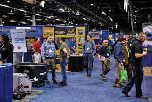
Figure 1: Total Trenchless of Calgary, AB installing pilot Developments in recent years diameter due to auger flight restriction,
tubes for a guided auger boring project.the final diameter of the steel casing hammer. community now shows it as a preferred
should be determined after considering Guided Ramming Heads are technique in several applications.
the geotechnical conditions along the During the
alignment. Guided Pipe
Guided Auger Boring allows several Ramming Method,
types of cutter head options based on the the steel casing
ground conditions that are anticipated. is advanced by
For moderately displaceable ground the pipe ram
conditions, which are typically viewed as and follows the
having a blow count or N-value of less intended alignment
than 30 blows per ft., Akkerman suggests provided by the
using a standard Weld-On Reaming Head Figure 3: Guided Ramming Head (GRH) installed pilot
(WORH) to transition from the pilot tube tubes on line and
to the steel casing. Shown in the figure manufactured with the same attention to grade. As the steel casing advances and
below, the WORH allows the contractor detail required for alignment, however, is displaced into the ground, the spoil is
to insert a lead auger into the casing for different steel properties are used, and forced into the casing pipe. The spoils
spoil removal. As the casing is advanced, they include both external and internal are not removed from the inside of
the rotating auger conveys the material relief bands with a more tapered the casing until the end of the bore or
to the reception shaft. An advantage arm design promoting lower thrust excessive thrust loads are being realized.
of the WORH is that the contractor can requirements. Cobbles and boulders that may have
easily trip back the augers in an event Guided Pipe Ramming has been been too large for removal via augers
there is an obstruction as the connection becoming an increasingly popular are potentially swallowed by the casing
to the pilot tubes is rigid through the trenchless method as it is effective in or displaced to the outside of the pipe,
steel casing. If the ground conditions a wide variety of ground conditions while the spoil inside the casing acts as
appear to ravel or flow, the contractor proven difficult with auger boring such a plug for unstable ground conditions.
also has the ability to remove a section as gravely, boulder-laden, and unstable Removal of the spoils is typically done
of auger. This creates a natural plug in ground. This method was popularized with augers or slurry with no risk of over
the lead section of casing prior to the as a back-up in the event Guided Auger excavation since an encasement pipe is
excavation process and promotes a stable Boring projects had encountered difficult fully inserted along the entire alignment.
face. ground conditions or obstructions along The Akkerman Model 240A GBM
the alignment. In system is the perfect compliment for
situations where both Guided Auger Boring and Guided
manned entry Pipe Ramming. Contractors now have
was not permitted the option to use the 240A system on
for obstruction any manufacturer’s auger boring rig with
removal or a “911 the adjustable base frame and remote
shaft” could not power pack or use directly with a MBM
be constructed, auger boring rig that features the GBM
contractors often quick connect package from Michael
employed the Byrne Manufacturing. To discover the
Figure 2: Akkerman Weld-On Reaming Heads (WORH)
force of a pneumatic versatility of Akkerman’s guided boring
In most applications, casing diameters hammer to “thump” the casing across products, visit our website, or contact
up to 36 inches can be installed by while allowing it to swallow the one of Akkerman’s knowledgeable sales
connecting directly behind the pilot obstruction. Over time the success representatives for more information.
tubes. For larger installations, it is of this method became more visible
recommended to incrementally step-up and acceptance in the engineering
the size of the casing to provide adequate
bearing support to promote an accurate
alignment.
Guided Pipe Ramming combines the AMERICAN MADE SINCE 1973
line and grade accuracy of the pilot tube
installation with the power of a pipe
ram affixed to the rear of the casing to
provide pulsing thrust loads. +1 (800) 533.0386
During the Guided Pipe Ramming
process, the steel casing is attached to
58256 266th Street
the pilot tube string with a special Guided Brownsdale, MN USA
Ramming Head. Appearing very similar
to the Weld-On Reaming Head (WORH)
shown in Figure 2, the ramming head is
purposely built to withstand the extreme
loads applied through the pneumatic AKKERMAN.COMHANDS-FREE
TECHNOLOGY
KEEP YOUR CREW SAFE
WITH THE SOLUTION THAT
CHANGES HOW EXIT-SIDE
WORK GETS DONE:
TONGHAND®
ACCESS TONGHAND ®
VIDEO & DETAILS
SAFE. PRECISE. PRODUCTIVE. ®
lavalleyindustries.com
18 | NASTT-NW JOURNAL | Fall/Winter 2021 BACK TO CONTENTSNASTT 2021 No-Dig Show
Orlando, FL
CASE STUDY:
THE DESIGNED AND CONSTRUCTED
MICROTUNNEL FOR THE DOWNTOWN CALGARY
TRANSMISSION REINFORCEMENT PROJECT
Samuel Wilson, P.Eng, CCI Inc., Edmonton, Alberta
Thomas Husch, CET, CCI Inc., Edmonton, Alberta
ABSTRACT methodology options to develop trenchless Figure 1. Project Location
designs at critical points along the route
As part of the ENMAX Power Downtown
through Calgary, a major city of more than
Calgary Transmission Reinforcement
one million people in the western Canadian
Project (DCTRP), ENMAX Power
province of Alberta. This project involves
Corporation (ENMAX) constructed a
the construction of a 138 kV single circuit
138 kv electrical transmission powerline
transmission line to meet the increased
between two existing substations within
power demands of downtown Calgary.
downtown Calgary, Alberta. Some
Continuing after the initial feasibility
portions of this route were designed with
assessments, the CCI scope was increased
a trenchless methodology to reduce the
to develop “Issued for Review” 90%
impact of construction activities within the
microtunnel design drawings, to be used
downtown core and other sensitive areas.
as required for permit applications and
In all, 1,517 m (4,977) of microtunnel was
to be provided in the bid packages for
designed for this project.
the construction work. Alternative Direct engineering support throughout construction
The most critical section of the DCTRP
Pipe Installation (DPI) for the Blackfoot and develop final as-built drawings.
was the construction of this powerline to
Trail/Canada Pacific (CP) Rail crossing, The 9th Street microtunnel was divided
be completed through a highly congested
and Guided Auger Bore crossing designs into two S-bend drives under 9th Street,
corridor of the downtown core in Calgary.
for the Elbow River were also developed in a north and south alignment with the
To avoid the obvious impacts to public and
at this phase of the project for the Owner proposed common launch point in a parking
private transportation that conventional
to adequately evaluate the economics of lot between 9th Ave and CP Rail right-of-
open-trench excavation would impose, CCI
these alternate crossing options in the way. Both microtunnel alignments passed
designed this critical section with a complex
marketplace. The successful contractor under densely packed urban traffic roads,
microtunnel primarily under 9th Street.
was expected to finalize the most feasible freight rail, light passenger rail, pedestrian
The unique nature of this product,
designs for each installation based on their crossings, and hundreds of infrastructure
complex design, congested logistics,
construction execution plan. crossings. Receiving pits were targeted near
length, and difficult ground conditions
The successful contractor that was 5th Ave to the north, and 14th Ave to the
has likely expanded the capabilities of
awarded the construction work for south. The nominal depth of approximately
microtunnelling and possible project
the DCTRP was Robert B. Somerville 10 m was chosen for the 1,540 mm (~60")
scopes in the industry. This article looks at
Co. Limited (Somerville). Somerville’s reinforced concrete pipe under 9th Street.
the challenges faced both during the design
subcontractor selected to complete the The north tunnel length was 468 m (1,535'),
and construction phases of this project.
microtunnel construction was Ward & while the south tunnel length was 510
Burke Microtunnelling Ltd. (Ward & m (1,673') for a total of 978 m (3,208')
PROJECT BACKGROUND Burke). CCI was then further engaged when from the single common launch pit. Both
subcontracted by Somerville to finalize microtunnels required complex S-bend
CCI was initially contracted by ENMAX, the microtunnel designs based on Ward & designs and were constructed primarily
a regional electrical utility to assist in Burke’s execution plan and construction through mudstone/siltstone, then gravel
feasibility assessments on general routing practices input, under Somerville’s project with silt and sand as the tunnel transitions
options for the project as well as trenchless requirements. CCI’s scope was to provide up towards each shallower exit pit.
BACK TO CONTENTS NASTT-NW.COM | 19Additional challenging microtunnel Table 1. DCTRP Trenchless Crossings
crossing designs were also developed as
part of this project, under the Elbow River, Crossing Length
MacLeod Trail, and Blackfoot Trail/CP Rail 9th St. North Drive 468 m (1,535')
but are not the main subject of this paper. 9th St. South Drive 510 m (1,673')
Elbow River Crossing at the 1st St. SE Bridge 96 m (315')
PROJECT ROUTING Macleod Trail Crossing 135 m (443')
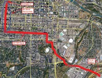
CCI assisted with completing a routing Cartmouth Rd., CP Railway, and Blackfoot Tr. Crossing 308 m (1,010')
assessment for the entire DCTRP project
throughout the early stages of the project,
providing input on the trenchless design Figure 2. DCTRP Route
requirements for the various proposed
options. The route traversed through
downtown Calgary from a power station
at 32nd Ave and 10th Street SE to the
ENMAX Substation 8 at 4th Ave and 8th
Street SW in the downtown core.
The final selected route included five
trenchless installations, listed in Table 1 at
top right.
The final route is shown in Figure 2, at
middle right.
METHODOLOGIES CONSIDERED
CCI completed a detailed methodology
review for each of the identified crossing
locations. The methodologies considered
included Horizontal Directional Drilling
(HDD), direct pipe installation, jack and
bore, and microtunneling.
Each crossing site had various
workspace restrictions, length, and depth
considerations, and varying geotechnical
condition considerations. HDD and jack
and bore were quickly ruled out for
all but the Elbow River crossing due Figure 3. 9th St. Microtunnel Geotechnical Formations
to the previously noted restrictions.
Direct pipe and microtunnelling were
progressed through the design phase of
the Blackfoot Trail/CP Rail crossing before
ultimately selecting microtunnelling as the
methodology which would be utilized for
all of the project crossings.
“THE UNIQUE NATURE OF THIS PRODUCT, COMPLEX DESIGN,
CONGESTED LOGISTICS, LENGTH, AND DIFFICULT GROUND CONDITIONS
HAS LIKELY EXPANDED THE CAPABILITIES OF MICROTUNNELLING AND
POSSIBLE PROJECT SCOPES IN THE INDUSTRY.”
20 | NASTT-NW JOURNAL | Fall/Winter 2021 BACK TO CONTENTSFigure 4. 9th St. Microtunnel Cross Section feasible routing was to traverse north along
9th Street SW. The route minimized the
overall construction within the downtown
core and provided a direct path to Substation
8 from the residential area at 9th Street
and 14th Ave SW to the final destination.
The identification of viable workspaces for
the location of launch and receiving shafts
required for microtunnel construction
contributed to the feasibility of the route.
The microtunnel design underneath 9th
Street SW was split up into two separate
drives, both starting at a shared launch
shaft located on the south side of the
intersection of 9th Street and 9th Ave SW,
on the north side of the CP Rail tracks.
The design paths for both drives
included crossings of multiple
infrastructure elements, including roads,
railroads, light rail tracks, buried power
and telecom cables, sanitary sewer, storm
varied with depth and bedrock type, with sewer, and water lines. Additionally, pile
GEOTECHNICAL INVESTIGATION the shallow mudstone bedrock having foundations for LRT structures had to be
estimated unconfined compressive strength considered in the final design. Multiple
A geotechnical investigation carried out by up to 2.0 MPa within the upper 3 m with daylighting and survey programs were
Tetra Tech Canada Inc. was completed for higher strength of 8 MPa expected in the conducted to determine the location and
the project, which investigated and compiled siltstone and sandstone. elevations of critical infrastructure.
borehole logs of the expected formations to Slotted PVC groundwater monitoring The LRT structure pile foundation data
be encountered during construction. For wells were installed in all boreholes. was not available in the initial data set
the 9th Street microtunnel, comprised of Groundwater was observed in all during early design work. LRT structures
a North and a South microtunnel drive, a boreholes except BH-08 and was measured included signal poles, catenary poles, and
total of nine boreholes were drilled along the during drilling at depths ranging from service boxes. Early construction surveys
anticipated route. approximately 3.1 m to 12.2 m. It was identified these structures and records were
Gravel, sand, and clay fill materials were ascertained that groundwater was at the found regarding the as-built depths of each
encountered in all boreholes beneath the elevation where granular materials were pile. Slight design profile modifications
asphalt pavement. encountered. Groundwater in this area were required on the north drive to
The glaciofluvial sands and gravels is hydraulically connected to the Bow maintain a minimum clearance of 3 m from
were encountered at depths ranging from River, which is located approximately the piles during the final design stage.
0.3 m to 7.4 m, typically overlying glacial 150 m northwest of BH-01 with a surface To facilitate crossing agreements with
till deposits. Gravels were typically sandy, approximately 10 m below the street surface. the LRT authority all pile structures
poorly graded, with trace to some cobbles were surveyed to determine their top of
with potential boulders. Sand deposits were foundation elevation, then the as-built
encountered in two boreholes and were 9th STREET ENGINEERING information for the depth of each was used
poorly graded to compact. to determine proximity to the microtunnel
Glacial till deposits comprised of clay, For the 9th Street microtunnel drives, the path. Specialized “Issued for Permit”
silt, and sand were encountered in every specified minimum inside diameter for the drawings were drafted that showed the
borehole below granular deposit except for microtunnel jacking pipe was 1,200 mm proximity to each structure to facilitate
BH-08. The majority of glacial till deposits and were specified to be made of reinforced crossing agreements. To complement
encountered were clay till, which was concrete with a maximum outside tunnel the clearances to the underground pile
generally described as silty, some sand to diameter of 1,524 mm. The final tunnel structures shown on the drawings, the
sandy, trace to some gravel, damp to moist, cross section is shown in Figure 4, survey elevations and calculated bottom of
low to medium plastic with varying N including the arrangement of the power foundation elevations were included as well.
values. The silt and sand till encountered cables to be installed once the trenchless The depth of each of the drives was
was described with trace gravel, non- installation was completed. designed to provide adequate clearance
plastic, and compact to very dense. The final tunnel cross section from other underground infrastructure and
Bedrock consisting of primarily exceeded the requirements for the 138 kV to maintain the tunnel paths within either
mudstone and siltstone, with occasional transmission line but allowed for future the glacial till material or the bedrock
sandstone layers was encountered in all installations to be pulled through. formation. Where possible, horizontal and
boreholes ranging in depth from 5.5 m to vertical curves in the tunnel path were kept
13.7 m, with the deepest bedrock in the Alignment Details nearer the receiving shafts to minimize
northernmost borehole BH-01 and the Multiple alignments were considered to stress on the casing pipe joints. This was
shallowest in BH-08. Bedrock strength reach substation 8. The most favourable possible for the vertical curves in both
BACK TO CONTENTS NASTT-NW.COM | 21drives; however, this was not possible for consideration for placement of permanent below ground surface for 414 m. An
the horizontal alignment of the tunnel path, manholes to access the constructed power “S” bend curve was included within the
and horizontal curves along the alignment utility. Manhole design was completed by horizontal tangent to navigate down the
of both drives had to be implemented other parties and planned for placement roadway and not intercept any buildings
to maintain the tunnel path within the of pre-cast concrete manholes within or utilities. The curves were designed at
allowable utility corridor of 9th Street and the construction shafts before backfilling a 400 m radius for a length of 99 m and
to stay out of any private property for both the excavation. 98 m. The final concrete pipe selected by
the launch shaft and tunnel path, except the tunnelling contractor used specially
for where rights-of-way encroachments had designed rubber gaskets at the pipe joints
been granted. 9th ST. NORTH MICROTUNNEL DESIGN to allow for articulation of the pipe along
In addition to the amount of space the radii specified on the drill path while
required for equipment and construction The north drive was launched from withstanding the expected jacking forces.
activities, shaft design also included horizontal at approximately 12 m depth At 414 m measured distance from
the launch shaft, a vertical curve was
included in the design profile at a 308 m
radius for a 27 m length into a 5-degree
tangent that extended to the receiving
shaft. This final portion of the design had
been modified prior to construction to
provide the required clearance to the pile
foundation for the LRT structures. Design
modifications included:
• Decrease in vertical curve radius from
400 m to 308 m
• Increase in angle of the final exit
tangent from 2 degrees to 5 degrees
• Change in location of the vertical
curve from 311 m from launch to
414 m from launch
• Increase of receiving shaft depth from
5.8 m to 8.7 m
• Modification of the alignment,
including the lengths and deflections of
the horizontal curves to accommodate
the relocation of the vertical curve
AA/EOE/M/W/Vet/Disability
without creating the need for a
compound curve
The final designed slack length of the
north drive was 468 m.
Michels Canada can tackle even the most
challenging trenchless projects.
Our construction and maintenance services can be delivered in many
9th ST. SOUTH MICROTUNNEL DESIGN
alternative delivery formats, including Design Build, CMAR, RFQ-RFP, and
The south drive launched from the
Traditional Bid/Build:
shared launch shaft at a 0-degree angle
• Storage and Conveyance • Cured-in-Place Pipe (CIPP) and crossed beneath the CP Rail tracks
• Tunneling and Microtunneling • Spray-in-Place Pipe (SIPP) along a straight alignment crossing
• Horizontal Directional Drilling • Sliplining - FRP & GRP through the private property on either
side of the tracks. A 3 m wide right-
• Direct Pipe ®
of-way was obtained to install the
microtunnel within the private property.
The right of way on both properties was
contained within the portion of each
property used as a parking lot. Another
“S” curve was required immediately after
crossing the tracks to bring the bore
An Energy & Infrastructure Contractor path in alignment with 9th Street on the
south side of the tracks. Additionally,
1102-16 Ave, Nisku, AB | 891 Rowntree Dairy Rd, Woodbridge, ON | 601 West Cordova St Suite #280, Vancouver, BC
the alignment had to avoid the private
www.MichelsCanada.com property and building foundations
immediately south of the tracks across
10th Ave. The horizontal curves were
22 | NASTT-NW JOURNAL | Fall/Winter 2021 BACK TO CONTENTSFigure 5. 9th St. North and South Drive Design Alignment and Profile
JACKING FORCE CALCULATIONS
Industry standard calculations were used to
calculate the jacking force for the jacking of
the pipe and Microtunnel Boring Machine
(MTBM). The jacking force calculation
incorporates the following:
• The front force at the cutting head of the
microtunnelling machine that is required
to excavate the material is a combination
of the support pressure (derived from
Table 2. 9th St. North Drive Jacking Force the depth of the tunnelling machine,
depth of water table and soil properties)
Dynamic w/ Safety Factor (1.5x) Static w/ Safety Factor (1.5x)
and the mechanical force required to
1,615,938 lbs 2,423,908 lbs 2,379,576 lbs 3,569,363 lbs turn the cutter head.
• The friction between the pipeline and
lubricant fluid which is calculated from
Table 3. 9th St. South Drive Jacking Force
the circumference of the pipe, length of
Dynamic w/ Safety Factor (1.5x) Static w/ Safety Factor (1.5x) pipe within the borehole, and the friction
coefficient between the pipe and fluid.
1,759,888 lbs 2,639,831 lbs 2,450,199 lbs 3,675,298 lbs
• The friction between the pipeline and
the borehole wall which is calculated by
multiplying the effective weight of the
designed with 400 m radii and were during the construction of the receiving section (depends on buoyant condition
49 m and 44 m long. The vertical curve shaft north of 14th Ave. of the pipe sections), coefficient of
was incorporated 400 m into the tunnel Design modification prior to friction, and the length of the section in
path design at a radius of 300 m into a construction due to the surveyed location of the borehole.
final tangent at 2.5 degrees. the manhole and storm sewer included: • The tunnel path is divided into a
Two design changes were required • Shift in horizontal alignment, including sequence of straight and curved
immediately prior to and during minor changes in the horizontal curve sections. At each section, the frictional
construction. The design change geometry and a shift 0.5m west of the forces between the pipeline and the
prior to construction was to maintain straight portion of the alignment and the borehole, and the pipeline and the
clearance from a surveyed manhole receiving shaft within 9th Ave lubricant fluid from the previous section
location south of the launch shaft as Design changes during construction (if applicable), is added to the value for
the tunnel path crossed 10th Ave SW to maintain the tunnel path within the the current section. Straight and curved
and to provide additional clearance to bedrock included: sections can be seen in Figure 5.
the daylighted locations of the storm • Decrease in vertical curve radius from • The friction force between the soil and
sewer line near the receiving shaft 400 m to 300 m pipeline will increase in the curved
north of 14th Ave. The design change • Change in location of the vertical curve sections if the effective weight of the
during construction was based on the from 343 m from launch to 400 m from pipeline (due to buoyancy) is lower.
tunnelling subcontractors request to launch The total built up friction force at the
maintain the tunnel path within the • Increase of receiving shaft depth from end of the curve is calculated based
bedrock for as long as possible and 6.8 m to 8.8 m on the friction force at the beginning
was based on the observed formation • Increase in launch elevation by 0.35 m of the curve.
Figure 6. Settlement Calculations
BACK TO CONTENTS NASTT-NW.COM | 23Jacking force calculations were repeated Crossing Permit Support Considering a borehole size of
for all tangents and curved sections To facilitate the approval of third party 1,524 mm, the minimum OD of casing
to reach the maximum expected crossing permits, CCI provided application pipe suitable is 1,424 mm, which equates
values listed. Theoretical jacking force support to the Owner in the form of to approximately 50 mm of allowable
calculations for design did not consider application submissions, Issued for Permit radial overcut. The resulting expected
use of intermediate jacking stations. design drawings, technical clarification settlements under road and rail are within
Construction included the utilization support, and compliance reviews. acceptable tolerances at this overcut gap.
of internal jacking stations (IJS) to In particular, the crossing of the CP Rail On the north drive, crossing beneath
distribute and reduce the total required INFO
right-of-way to the south required a detailed SPECS
the LRT required significant technical
FileName:21-2281CA_Ad_RZ_NorthWest_Trenchless_Journal_UTT Page Size: 4.325" x 7"
jacking force that was applied
Job#: 21-2281 from the application and1 review process. Settlement
Number of Pages: coordination with the rail operations group
launch point during construction of calculations
Artist: Sue Bonofiglio Email: scianciullo@mapei.com
114 4 E. Newpor t Center Dr.
Date: September 1, 2021 3:24 PM
Deerfield Beach, FL 33442
were assessed at the maximum
Bleed: Yes Amount: .125"
Colors: CMYK Process, 4/0
to ensure tunnelling activities would not
each installation. allowable overcut gap (see Figure 6).
N O T E : C O L O R S V I E W E D O N - S C R E E N A R E I N T E N D E D F O R V I S U A L R E F E R E N C E O N L Y A N D M A Y N O T M A T C H T H E F I N A L P R I N T E D P R O D U C T. have any impact to the rail or public.
CCI provided additional permit drawings
including proximities to all below ground
LRT structures to support the crossing
permit application.
The entry shaft was constructed
within a City-owned parking lot approved
for project use. However, private lot
boundaries adjacent to this entry location
restricted options for optimized location
and orientation of the north and south
drives and required further assessment
of proximity to building foundations and
potential impact of the microtunnels.
Furthermore, the numerous buried utility
crossings seen within these crossings
added to the various crossing agreement
requirements and reviews completed as
part of the design process.
CONSTRUCTION
The combined construction team,
including Somerville, Warde and Burke,
and CCI completed the final IFC package
for the proposed project prior to execution.
Launch and Receiving Shafts
Ward and Burke completed the
engineering for the temporary concrete
caisson shafts required for construction.
The wall sections of the shaft are each
constructed at ground level. The walls of
the shaft were constructed from reinforced
cast in place concrete that provide a rigid
structure that will resist all the lateral earth
MINING SOLUTIONS loads applied.
Steel sheet piles were not selected for
the construction of the shafts primarily
• Injection/Consolidation/Anchoring based on two considerations. The first
• Technologies for Shotcrete & Concrete is the high impact and vibration caused
by construction that could affect nearby
• Rehabilitation
structures and cause further disturbance
• Concrete Protection and Final Coating in the congested area of construction. The
• Waterproofing second consideration was the necessity
to cut a hole in the metal through which
to launch the MTBM, leaving the ground
utt.mapei.com temporarily unsupported with the
potential for soil and/or groundwater to
flow into the shaft.
24 | NASTT-NW JOURNAL | Fall/Winter 2021 BACK TO CONTENTSThe structure sinks under its own weight Figure 7. Reinforced Concrete Pipe
on the bottom cutting edge as the ground
inside the shaft is excavated in and even
manner. Once the walls are at the correct
depth, the concrete floor is poured. Once
the floor has been set, any groundwater
within the shaft is pumped out. This method
of caisson shaft construction eliminated
the need for continuous dewatering as the
structure was completely sealed once the
concrete wall base is placed.
A launch seal is bolted to a flat formed
concrete face on the shaft wall before the
MTBM launches. The MTBM advances
through the seal and tunnels through the
concrete wall that has been left free of any
reinforcement then progresses into the
soil or rock formation. This methodology
ensured that groundwater ingress into the
shaft was prevented during the launch of
the MTBM and allowed the contractor to
support the annular space between the Microtunnel Construction Figure 8. Jacking Frame in Launch Shaft
overcut and the Reinforced Concrete Pipe Pipe Design
(RCP) using the bentonite lubrication The contractor selected reinforced precast
fluid. This in turn reduced frictional forces concrete pipe (Class V) with an outside
and helps to mitigate settlement on surface diameter of 1,490 mm and the prescribed
due to soil collapse around the pipe. minimum inside diameter of 1,200 mm,
Final shaft depths were: which was suitable to satisfy the intent
• Launch Shaft = 13.7 m of the design. Joints of the casing pipe
• North Receiving Shaft = 8.7 m contained a rubber gasket protected by
• South Receiving Shaft = 9.0 m a circumferential steel band collar. The
The depths included the base slabs which gasket was compressed with each joint of
for the receiving shafts, were a 600 mm pipe during installation and was designed
concrete slab and for the launch shaft to withstand a hydrostatic head of over
a 1,000 mm-thick base slab with an 30 m. The selected pipe also allowed for
additional 500 mm reinforced concrete installation of lubrication ports, which
slab above it. The first slab provides the were placed at regular intervals along the monitoring of multiple tunnelling
initial seal of the bottom of the shaft, drive length, allowing for the injection parameters such as slurry pressure.
allowing any water to be removed from the of bentonite lubrication to minimize the The pressure and viscosity of the
shaft. The second base layer is poured in jacking forces required lubricating fluid pumped into the overcut
the dry base of the shaft to be used as the had to be sufficient to ensure that the
work surface. Microtunnel Boring Machine (MTBM) surrounding soils did not collapse on the
The launch shaft outer dimensions were An AVN1200 Herrenknecht casing pipe. If cohesionless soils were
9.8 m long and 7.2 m wide, with inner Microtunnelling Boring Machine was encountered, it was expected that pressures
dimension of 8.2m long and 6.0 m wide. selected to be used with a mixed of up to 5–6 bar would be required to
The receiving shaft outer dimensions face cutter head. The cutterhead was support the annulus.
were an outer diameter of 5.2m (4.8 m selected for the robust structure and was Once the drive was completed, a grout
radii with 0.4 m infills) and an inner specifically designed by Herrenknecht mixture was pumped through the injection
diameter of 4.0 m. for types of soil conditions present ports to maintain ground stability and
Challenges that arose during along the designed tunnel path. The mitigate the risk of surface settlement.
construction were primarily related to the MTBM created a 25 mm radial overcut
actual daylighted and surveyed location of around the casing pipe which was Jacking Frame/IJS
the storm sewer compared to the as built supported by the bentonite lubricant The jacking frame provided by the
location which the design was based on. during the tunnelling process and contractor was of a unique space-saving
The south shaft of the 9th Street south intended to maintain the annular space design and provided a maximum 3 m
drive was required to shift 0.5 m to the of the tunnel machine to reduce risk of stroke to install the 3 m long RCP sections.
west to maintain a minimum of 1.0 m soil settlement. The MTBM cutterhead Intermediate jacking stations were
from the storm sewer. An underground allowed for pressure to be maintained installed at regular intervals and at
telecom cable was also present within the at the tunnel face, ensuring the specific positions within the casing pipe.
planned location of this receiving shaft and stability of the tunnel face throughout Placement of these stations considered
was moved for construction with approval the excavation cycle. The MTBM the geometry of the designed tunnel
from the utility owner. system included sensors for real-time path to reduce the overall jacking force
BACK TO CONTENTS NASTT-NW.COM | 25required of the main jacking frame to as long as practical. This was to eliminate alignment of the drive, only a handful of
complete the drive and navigate through risks associated with exiting the bedrock tie backs were actually intercepted, causing
the designed tunnel path. at a shallow angle and tunnelling into the minimal delays due to tunnelling through
undesirable material above it. Primary risks the tie backs.
Construction Summary increased by exiting the bedrock included Outside of the design changes
During the excavation of the receiving shaft overmining and settlement of the roadway. described previously, overall construction
on the north side of 14th Ave, the granular Temporary construction tie backs were activities progressed smoothly with
and glacial till material encountered was intercepted during the drive process. minimal delays or incidents, resulting in
less favourable for tunnelling than initially These tie backs were initially utilized in completion of the tunnelling activities
determined based on the geotechnical the excavation for the construction of according to schedule.
investigation. The design was modified the surrounding buildings and were not
as described in section 8 to maintain the removed post construction. As-built data CONCLUSION
drive within the bedrock formation for was reviewed and due to the curving
The ENMAX DCTRP project was
designed and constructed successfully
utilizing a high degree of care in the
engineering design and construction
implementation. CCI is proud to have
been an instrumental part of this project
which was completed with the utmost
consideration for safety to the personnel,
public, and environment and would
like to thank ENMAX, Somerville, and
Ward & Burke for their teamwork and
professionalism contributing to the
overall success of the project.
REFERENCE MATERIAL
Reference material used in the engineering
of the microtunnels included:
ASCE/CI 36-15. Standard Design
and Construction Guidelines for
Microtunneling.
Bennett, Robert D., 1998. "Jacking
Loads and Ground Deformations
Associated with Microtunneling,” Ph.D.
Dissertation, University of Illinois at
Urbana Champaign, Urbana, IL.
Das, B.M., 2008, Fundamentals of
Geotechnical Engineering, Third
Edition, Cengage Learning, Samford,
CT, pp. 245.
Geniev, G.A., Effect of Soil Loosening On
the Ground Surface Above Unbraced
Underground Working, Soil Mechanics
and Foundation Engineering, Vol. 37,
No. 6, 2000.
HDD Good Practices Guidelines, HDD
Consortium, Third Edition (2008),
pp. 125.
J.P. Pruiksma, D. Pfeff, and H.M.G. Kruse,
Technical Document “The Calculation
of Thrust Force for Pipeline Installation
using the Direct Pipe Method.”
Wallin, M., Wallin, K., Bennett, D., 2008,
"Analysis and Mitigation of Settlement
Risks in New Trenchless Installations,”
North American Society for Trenchless
Technology 2008 No-Dig Conference
& Exhibition, Dallas, TX.
26 | NASTT-NW JOURNAL | Fall/Winter 2021 BACK TO CONTENTSYou can also read