Technical Flood Risk Guidance for Stakeholders - SEPA requirements for undertaking a Flood Risk Assessment
←
→
Page content transcription
If your browser does not render page correctly, please read the page content below

Technical Flood Risk Guidance for Stakeholders
 - SEPA requirements for undertaking a Flood Risk Assessment -

Version 12, May 2019

SS-NFR-P-002
Contents
1. Introduction
2. SEPA Flood Maps
3. Requirements for Flood Risk Assessment (FRA)
3.1 Introduction
3.2 Minimum Requirements for Flood Risk Assessment
3.3 Detailed Flood Risk Assessment
4. Guidance for Fluvial Design Flow Estimation
4.1 Introduction
4.2 FEH Statistical Method
4.3 FEH Rainfall-Runoff Method
4.4 Revitalised Flood Hydrograph Method (ReFH2)
5. Guidance for Hydraulic Modelling
5.1 Introduction
5.2 Requirements for Hydraulic Modelling Studies
5.3 1D Hydraulic Modelling
5.4 2D Hydraulic Modelling
6. Guidance for Coastal Flood Risk Assessment
6.1 Introduction
6.2 Coastal Flood Levels
6.3 Freeboard and Climate Change
6.4 Coastal Flood Modelling
6.5 Joint Probability Analysis
7. Surface Water
7.1 Introduction
7.2 Guidance for Surface Water Modelling
7.2.1 Hydrological Parameters
7.2.2 Digital Terrain Model
7.2.3 Model Verification
8. Groundwater
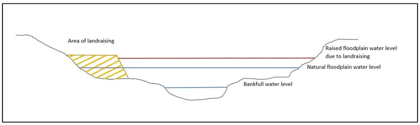
9. Land Raising and Compensatory Storage
9.1 Introduction
9.2 Compensatory Storage Proposals
9.3 Modelling Issues
Appendix 1: SEPA Flood Risk Assessment Checklist
Appendix 2: Sources of Flooding
Appendix 3: Potential Sources of Flood Risk Information
Appendix 4: Flood Probability
Appendix 5: Glossary1. Introduction
This document is designed to outline what information SEPA requires to be submitted as part of a
Flood Risk Assessment (FRA) and to outline methodologies that may be appropriate for design flow
estimation (hydrological modelling) and hydraulic modelling. The complexity of the FRA required will
reflect the nature of the flooding problems, the mechanisms of flooding, and the characteristics of the
site, rather than the complexity or scale of the proposed development. An FRA should be undertaken
where any available information indicates there may be a risk of flooding to the site, or development
of the site may increase risk elsewhere. The FRA must include sufficient information to provide a
robust assessment of flood risk. The Planning Authority ultimately determines the requirement for an
FRA to be undertaken.
SEPA is an independent advisor on flood risk within the context of National Planning Policy. This
includes a statutory role to provide flood risk advice for certain consultations. In line with the SEPA-
Planning Authority Protocol (Policy 41), where SEPA receives an FRA in connection to a planning
application that raises fluvial or coastal flooding issues, it will:
- Audit the FRA and advise on the soundness of the data used, methodology, conclusions, and
recommendations proposed.
- Provide its own advice and comment on flood risk to the Planning Authority based on the
audited FRA, and any other information held by or available to SEPA and reviewed in line with
Scottish Planning Policy and the Flood Risk Management (Scotland) Act 2009.
The cornerstone of sustainable flood risk management is the avoidance of flood risk in the first
instance. Flood Risk and Land Use Planning have a crucial role to play in ensuring that, wherever
possible, a sustainable approach is taken towards flood risk management and the functional floodplain
is protected. The clear presentation of data will enable an improved review and response time to
Planning Authorities. SEPA therefore recommends that this document is reviewed and the guidance
followed to ensure that appropriate techniques are applied, and sufficient information is supplied to
avoid unnecessary delays in the planning process.
This document is intended to assist developers in carrying out site specific FRAs to inform land use
planning. SEPA have provided other guidance that may be more appropriate depending on the
requirements of the study in question:
- A Strategic Flood Risk Assessment (SFRA) is designed for the purposes of informing the
development plan process (Local Development Plans). A SFRA involves the collection, analysis
and presentation of all existing flood risk information for the area of interest. A SFRA would
present a strategic overview of flood risk without necessarily meeting the reporting
requirements of a detailed site specific FRA. SEPA have prepared guidance on undertaking
Strategic Flood Risk Assessments.
- SEPA have also prepared Flood Modelling Guidance for Responsible Authorities that is
designed to support those key partners who are responsible for developing and
commissioning flood studies in respect of flood risk management planning. It provides
guidance on where uncertainty may arise in flood modelling and how it may be managed
through the modelling process so that it can inform appropriate decisions. Responsible
Authorities are encouraged to refer their contractors to that guidance to promote compliance
with best practice.2. SEPA Flood Maps The SEPA Flood Maps are intended as a high-level tool to support decision making for flood risk management, and land use planning at a strategic level. The SEPA Flood Maps have been produced following a consistent, nationally applied methodology for catchment areas equal or greater than 3km2 using a Digital Terrain Model (DTM) to define river corridors and low-lying coastal land. Small watercourses with catchments less than 3km2 will not be identified by the fluvial extent of the SEPA Flood Maps. Small watercourses are poorly understood with respect to the severity of the flood hazard that can be generated on a catchment of this scale. Therefore, if a small watercourse has not been identified by the SEPA Flood Maps, this should not be interpreted as there being an absence of risk. SEPA’s Coastal Flood Maps are based on the astronomical tide level plus a surge factor, but do not include wave action or wave overtopping. In some areas in Scotland, the maps are based on more detailed modelling. The flood extents shown by the SEPA Flood Maps are indicative in nature. The flood extents shown do not fully take account of structures such as culverts, bridges and that can influence local flooding. The SEPA Flood Maps do not account for fluvial and coastal flooding occurring simultaneously. Flood defences are generally not taken into account in the Flood Maps, but there are exceptions where more detailed modelling is available and this has been incorporated into the Flood Maps. In such circumstances, users of the SEPA Flood Map are advised to also check any the extents of any areas of benefit. The SEPA Flood Maps can be used, along with other sources of flood risk information, to provide an initial assessment of likely flood risk to a site. However, due to the indicative nature of the flood extents and necessary limitations of the methodology it does not make them suitable to explicitly quantify the potential flood risk at street or property level. Therefore, it is inappropriate for the SEPA Flood Maps to be used to assess flood risk to an individual property, or to be used to inform a detailed Flood Risk Assessment. The SEPA Flood maps cannot be used for commercial purposes, as outline in the Terms and Conditions of the maps, which all users must agree to before viewing the maps online. Key caveats exist regarding the use of the Flood Maps that should be read, understood and adhered to. Further details are available on the SEPA website. 3. Requirements for Flood Risk Assessment (FRA) 3.1 Introduction The functional floodplain is defined as land where there is a 0.5% or greater annual probability of flooding in any year. This probability is sometimes referred to as a 1 in 200-year flood. For development that falls under the ‘Most Vulnerable Use’ as defined by SEPA’s Land Use Vulnerability Guidance, the 0.1% annual probability (1 in 1000-year flood) should be assessed and, in the case of civil infrastructure, avoided. In certain complex cases, an FRA may be required to assess pluvial flooding. Further information on surface water and pluvial flooding is outlined in Chapter 7. An FRA for a specific site should investigate what the likelihood of flooding is, and should consider flood risk from all sources. It should demonstrate if the site is out with the required flood extent for
the relevant probability, or if development of the site would be, appropriate, then what acceptable
mitigation measures would be required. The complexity of the flooding mechanism(s) will inform the
scope of the FRA required, and the information required can take a variety of forms.
Prior to investing in an FRA, applicants should consider the potential outcome of the assessment. We
would caution that for some sites, providing additional information or a detailed flood risk assessment
may only serve to confirm that this site is within the functional floodplain and therefore not suitable
for development.
While SEPA will not provide recommendations for flood risk consultants, we offer the following advice
when commissioning flood risk assessments:
Contact more than one specialist or company to discuss your requirements and costs, ask for
references and follow them up.
Ask if they have experience in undertaking this type of assessment, taking into consideration
the complexity if the flooding mechanisms at the site.
Ask if their previous work has been accepted by SEPA in support of planning applications.
Ensure they are familiar with, and have used the guidance available on the SEPA website.
Consider if they have a potential advantage by having local knowledge and experience.
3.2 Minimum Requirements for Flood Risk Assessment
There are a number of methods, of varying complexity, that can be used to assess the flood risk for a
development, and assess any impacts elsewhere. SEPA’s advice will be based on the information
available at the time of consultation. Therefore, in order to receive the most detailed advice, and avoid
any unnecessary delays it is helpful to submit any supporting flood risk information at the application
stage, although there may be cases where after review, further flood risk information is still required.
SEPA welcome pre-application engagement with applicants and developers to discuss flood risk
considerations and to identify the supporting information that is likely to be required.
As a minimum, we would require the following information to be submitted for any site that requires
an FRA:
Plans: a clearly geo-referenced location plan at an appropriate scale that includes
geographical features and street names. The plan should identify all watercourses or other
bodies of water in the vicinity of the application site that may have an influence. This should
include drainage outfalls, overflows, and culverted watercourses. The site plan should show
the location of the proposed development and include information on any existing
development at the site that may be either retained or demolished.
Photos: Photographs of the site should show the area of the proposed development relative
to any watercourses or coastlines. Photos of the watercourse should show the channel, banks,
floodplain, and any culverts or structures. Labelling should be provided to clearly identify what
the photographs are showing (i.e. direction, location, flow direction etc.). Where possible a
scale (metre staff) should be included within the photographs themselves. Photos should
ideally be date stamped. If appropriate, other areas of importance should be identified and
photographed such as areas of erosion, trash-lines from flood events, areas of woody debris
accumulation etc. Topographic Information: As a minimum, a plan should be provided showing the existing
ground levels at the site, and if applicable the proposed ground levels and finished floor levels.
Any land raising should be clearly identified. Levels should be shown relative to Ordnance
Datum Newlyn or to the local OS datum for Shetland (Lerwick) and the Western Isles
(Stornoway).
Cross Sections: Other topographic information could include site cross-sections. Sections
should be of an appropriate length to include the application site, the channel bed levels, and
bank levels of the opposite bank. Levels should be shown relative the metres above Ordnance
Datum (Figure 1). Sections should always be taken perpendicular to the flow in the channel.
Figure 1. Example of appropriate site cross section.
As a minimum, sections would expected to be taken at points, upstream, downstream, and
through the site. However, the appropriate spacing and number of cross-sections will depend
on the physical characteristics of the channel e.g. taking into consideration the channel
uniformity and slope. Additional sections would also be required at keys areas of interest
including structures like bridges and culverts, significant changes in the channel or floodplain
width, slope, or roughness, and if applicable, at gauging stations where information is
available for calibration (Figure 2).
Figure 2. Example of suitable locations for cross sections. The number and spacing will
depend on channel characteristics and the complexity of the FRA or hydraulic model. Structural Information: Details of any structures, such as culverts, bridges, weirs, and croys,
which may influence water levels, should be provided. Further details on the conveyance
capacity of such structures may also be required. Therefore, information on the dimensions
of the structure including the opening shape, size, slope, length, invert and soffit level,
material and condition, and flood relief level should be provided, alongside any initial
assessment of the capacity of this structure.
Figure 3. Examples of key structural information required a. culvert and b. bridge
Other site-specific information: If applicable and available, details of any previous flooding at
the site including the date and time of the event. This information could be anecdotal, and if
possible photos of flooding or trash lines should be provided to obtain an indication of the
extent and depth of observed flooding. Although appropriate site photos should be provided,
if not available then a description of the channel and floodplain should be included. If relevant,
details of any existing flood alleviation measures should also be provided, along with the
confirmed Standard of Protection.
For some sites, this information may be sufficient for us to verify the flood risk and no further
information would be required. However, if this information were insufficient to provide a robust
assessment of the risk of flooding to the development or elsewhere, then a detailed flood risk
assessment would need to be provided, and carried out by a suitably qualified professional.
3.3 Detailed Flood Risk Assessment
When a more detailed FRA is required, methods should be applied in accordance with available
guidance, including the advice outlined in this document. Other literature and guidance could be used
for reference, and up-to-date industry standards as appropriate for the site in question should be
followed. All available local data and information of relevance should be utilised for any assessment.
A precautionary approach should be applied and particular attention paid to uncertainties and model
sensitivity.
The FRA should identify the source of potential flooding i.e. fluvial, coastal, surface water (pluvial), or
combinations of sources of flooding e.g. fluvial and coastal. The following chapters refer mainly tofluvial flood risk assessments that require hydraulic modelling. Other sources of flooding are discussed
in later chapters. Fluvial flood risk assessments should identify the following elements:
An assessment of appropriate design flows and flood levels at the site. This should provide
sufficient information on the derivation of the design flows for auditing purposes. More
detailed guidance on design flow estimation is presented in Chapter 4.
An assessment for future climate change should be carried out, in order to take a
precautionary and sustainable approach to flood risk assessment. Our recommendation is set
out in here albeit some local authorities may request a different standard be utilised by
developers.
Sensitivity analysis. Further guidance on sensitivity analysis is presented in Chapter 5.
Details of any structures (including culverts, embankments, walls etc.) that may influence local
hydraulics, and an assessment of how any structures may influence water levels at the site.
Where culverts provide a significant flow restriction, levels and discharge rates at which flow
would overtop the structure should be identified. An assessment of culvert blockage, and
likely impacts should be carried out.
The flood extent, depth, velocities, and flow pathways for appropriate return periods should
be indicated on a site plan that shows the footprint of the proposed development. Any site
sections should show the finished floor levels and any changes in ground level relative to the
modelled flood level.
An assessment should be made of the likely rate at which inundation may occur, or an
identification of the order at which areas of the site may flood. Publicly accessible dry
pedestrian access/egress routes to higher ground or refuge point should be clearly identified
on a plan.
Details of any mitigation measures proposed. In the case of any proposed land raising,
estimates should be made of the expected volumes of water, which would be displaced from
the site because of any land raising. For any land raising proposed, details of associated
compensatory storage should be provided. Further guidance on land raising and
compensatory storage is presented in Chapter 9.
If appropriate, an assessment of the off-site flood risk as a result of the development should
be made, identifying any changes in flows and levels upstream or downstream of the
development. An assessment should be made of the likely impact of any displaced water on
neighbouring locations by undertaking pre and post development modelling.
The FRA should conclude with a summary of its findings.
4. Guidance for Fluvial Design Flow Estimation
4.1 IntroductionEstimation of the design flow can be a significant variable in determining flood risk at a site. No single method is considered as always being able to provide the ‘right’ answer, but correct application of the Flood Estimation Handbook (FEH) should preferentially be used to estimate design flows, and more than one method should be used for comparison. The FRA should provide justification that the method used are the most appropriate for the specific site and catchment. While SEPA cannot always recommend one methodology over another, different factors need to be considered for different catchments and therefore we would have a preference for certain methods based on catchment specific circumstances. For each site the size and nature of the catchment needs to be considered, and if any gauged data and historic records of flooding are available. The FEH web service (or CD-ROM) defines the catchment area, and catchment descriptors for catchments >0.5km2. However, for small catchments, or catchments that are more ‘unusual’ for example those with a particularly flat topography or a number of artificial drainage channels we would require the catchment area to be verified against Ordnance Survey maps. If the catchment area is incorrectly defined then, this has implications for the catchment descriptors and flow estimation. Design flow estimation in small catchments has more uncertainties as there is usually a lack of gauging stations. Generally, FEH methods are suitable for catchments down to 0.5km2. The preferred method for estimating flow in catchments smaller than 0.5km2 is to use a suitably sized donor catchment with similar catchment descriptors and to scale the FEH method by area. While preference would be for FEH methods, other methods such as the Flood Studies Report or IH124 can be used in parallel where is they may be applied with justification. In these cases, the methods should be correctly labelled, and applied. Design flow estimation should be carried out using the professional judgement and experience of the flood risk consultant. The review of design flow estimations submitted, as part of an FRA, will be carried out based on the professional judgement and experience of SEPA’s flood risk hydrologists. However, this chapter provides advice that may assist in ensuring that best practice is followed and the most up-to-date and appropriate methods be used in assessments to aid consensus on the best approach. 4.2 FEH Statistical Method Hydrometric authorities hold flood data for many gauging stations not included in the FEH/National River Flows Archive (NRFA) UK database. Up to date station data should be included for all sites used in the analysis. Station data is available free of charge from the NRFA for all UK sites in Version 6 WINFAP-FEH dataset. For any stations with out of data, recent data should be requested. When using the statistical method, it should be considered if there are more appropriate gauging stations not included in the FEH/NRFA UK database, for use as donor sites and for inclusion in pooling groups. More recent data can be requested from SEPA via our data request online form. QMED is the median annual flood or the 1 in 2-year flood. QMED estimates should be improved using appropriate, hydrologically similar, local data, either from the catchment in question or nearby catchments, unless justification is provided for the use of catchment descriptors only. QMED should only be estimated from catchment descriptors as a last resort. The channel dimensions approach to estimate QMED may be acceptable as part of other methods for determining QMED as stated in the FEH.
Pooled analysis is usually required for large ungauged catchments. Revisions of FEH Pooling Groups
should always be considered. Pooling groups should include sites based on catchment/hydrological
‘similarity’ rather than geographical location, and stations within the groups need to include up-to-
date data. In some cases, single-site analysis may be more appropriate than using a pooling group,
particularly when long high quality gauged data is available, and the pooling group results do not
reflect the flood history of observed data sufficiently.

The FEH Vol 3.17.3.2 advises and studies have agreed that, on average the Generalised Logistic (GL)
distribution is considered to perform better than the Generalised Extreme Value (GEV) for pooled
growth curve derivation. The GEV distribution can be a better fit for flood data were a catchment
generally has significant flood storage available upstream provided by large lochs, reservoirs or
exceptional floodplain storage. The distribution that provides the “best fit” should usually be selected;
however, we recommend that a justification should be provided where the recommended GL
distribution is not applied.

A decision log or audit trail of the hydrological analysis undertaken should be provided to help ensure
that all relevant information has been provided and justified. This should include justification for what
stations were added and removed from pooling groups.

Up to date historical data should be incorporated into flood estimates where it is available. For
example, given the severity of the flooding in Winter 2015/16 it is particularly important that data
from those floods are included in any analysis. The latest version of WINFAP now has a function to use
historical data, and in some cases, this may provide the most suitable approach to flood estimation.

The FEH Statistical Method is often not suited to small catchments as there is a lack of small gauged
Scottish catchments in both the original FEH database and the updated NRFA UK database.

4.3 FEH Rainfall-Runoff Method

Rainfall-Runoff specifically relates to the re-statement of the FSR ‘unit hydrograph’ rainfall-runoff
method, which is outlined in Chapter 4 of the Flood Estimation Handbook. Our experience is that this
Rainfall Runoff method provides good estimates for small, ungauged catchments in Scotland and is
still a valid approach particularly where uncertainties are high and there is a lack of local data for
verification.

Rainfall-Runoff estimates can be made using the equations from FEH Volume 4, but there are also
functions in some hydraulic modelling software to obtain rainfall-runoff estimates. If using modelling
software for rainfall-runoff estimates, data from the FEH-99 Depth Duration Frequency Model (DDF)
should be used, as this is the dataset for which the method was calibrated. This can be taken from
either the FEH CD-ROM or from the FEH web service. There should be no difference in estimates
regardless of where the catchment descriptors have been extracted from, as there has been no change
to the parameters read by the software for the Rainfall-Runoff method.

The summer profile should only be selected if the catchment is small or heavily urbanised (URBEXT >
0.125).

Observed rainfall Records can be used for input into Rainfall-Runoff models, as well as improving the
parameter estimation of the model e.g. LAG. SEPA operate a large rainfall-monitoring network and
data is available on request.
The estimation of percentage runoff can be the most uncertain part of flood estimation and
sometimes a proxy is used. A better estimate of one such proxy e.g. standard percentage runoff (SPR)
is the most significant single improvement that can be made for any form of rainfall-runoff flood
estimation. FEH Vol 4.2.3 recommends a number of alternative methods for estimating SPR, both
theoretically and from observed data. Users of the Rainfall-Runoff method should take care in the
selection of an appropriate SPR estimate for the catchment.

The Flood Studies Report 1975 (FSR) which set out the Unit Hydrograph (rainfall-runoff method),
provided various methods to alter and enhance the approach given various circumstances. One
particular advantage of the FSR approach to simulation was the ability to alter the convolution of the
unit hydrograph with a dynamic SPR (standard percentage runoff) variable. This approach recognises
that during longer duration rainstorm events, the SPR can increase as a catchment ‘wets-up’ and
storage is lost. The method proved very effective in more accurately simulating past flood events.

Such FSR approaches should be retained within the suite of options available to the analyst, depending
on the nature of the particular hydrological problem they are faced with. Albeit rare within the sphere
of FRAs for land-use planning, for completeness, the FSR UH method is still the only UK standard
option for estimation of Probable Maximum Precipitation (PMP) and Probable Maximum Flood (PMF).

4.4 Revitalised Flood Hydrograph Method (ReFH)

The Revitalised Flood Hydrograph (ReFH) has been updated and calibrated for Scotland and launched
as ReFH2 (v2.2). SEPA is pleased to have contributed to the development of ReFH2.2 and the
improvements that have been made for Scotland. For ReFH2, only the FEH-13 DDF model should be
used, and this is only available from the FEH Web Service. The default Critical Storm duration should
be used for design peaks, and iteration used if looking for Critical Duration for a storage system.

While SEPA can recommend ReFH2 as contributing to the suite of methods available for design flow
estimation in Scotland, the method will not adequately represent likely flood flows in all parts of
Scotland as the calibration only uses a small number of Scottish gauges. We recognise that there is
still scope for further improvements, particularly relating to small catchment data. Data collected
during recent floods has highlighted the concerns SEPA still have with the robustness of flow estimates
made using ReFH2 in Scotland.. Therefore a precautionary approach is required to estimating flood
flows, although regardless of location, more than one appropriate flow estimation technique should
be considered, as described above.

If ReFH2 is used in design flow estimation, we would recommend the adjustment of default parameter
values, where relevant, for sites where superior local data exists or suitable donor data may be
available. We would also caution against the use of ReFH2 for catchments where lochs and reservoirs
exist, and the FARL value is less than 0.9, as the gauging stations selected to develop and test ReFH2
have FARL values greater than 0.9. For estimation of the Probable Maximum Flood (PMF) for reservoir
design, the FSR method as re-stated in the Flood Estimation Handbook should still be adhered to.
Please note that the ReFH2 presently does not allow the user to perform flood simulation of observed
events, only design.
5. Guidance for Hydraulic Modelling
5.1 Introduction
A hydraulic model is an approximate and simplified mathematical representation of the real world
hydraulic processes that govern flooding mechanisms in a particular area (the modelled reach).
Hydraulic modelling applications can range from simple Manning’s calculations to complex hydraulic
modelling solutions using a range of software packages. For flood modelling, a variety of modelling
methods and combination of methods are available, although this chapter will focus on 1D, 2D and
1D/2D linked fluvial hydraulic modelling. Coastal modelling and 0D (spreading method) pluvial
modelling is covered in chapters 6 and 7. Each modelling method has its own advantages and
disadvantages. Therefore, a final decision about the choice of model will be subject to many
considerations and should be appropriately justified.
Models should be provided to SEPA for review and audit, especially in the event of any discrepancy or
misinterpretation of information presented in the FRA. SEPA also reserve the right to request the
hydraulic model be provided, and may do so for complicated sites and Flood Protection Schemes (FPS).
Models may also be requested for smaller, less complicated sites as deemed appropriate. Where
models are to be provided we will also require the various files to run the model, including (but not
limited to) inflow files, boundary files, geometry files, initial conditions and log files. For 1D-2D models
evidence of mass balance checks should also be provided. The model log would also be particularly
helpful in assisting our in-house specialists to interpret the model and associated files. Confirmation
of the floodplain modelling approach used should be presented, particularly for 1D modelling.
5.2 Requirements for Hydraulic Modelling Studies
This section provides guidance on the parameters that should be presented as part of an FRA. The
requirements outlined below can apply to 1D, 2D, and linked 1D/2D models; however, the parameters
should be amended as appropriate depending on the complexity of the modelling and the application
site.
Statement of objective: This is required to demonstrate the modelling approach is fit for
purpose. It should clearly explain the situation being modelled and the objectives of the
modelling study, including details of the output required from the model.
Justification of the model: This is to demonstrate that the model used is suitable for this study.
It should include evidence of previous applications in similar circumstances and a
demonstration of experience in the application of the model. This should indicate the
particular modelling software used and its appropriateness for the situation.
Data collection: All relevant data collection and measurement techniques should be quoted,
including expected errors and relevant quality assurance. It is expected that appropriate input
data is collected to support the objectives of the study. Surveyed cross-sections of the channel
and floodplain should be comprehensive to avoid “glass walls” within the model. Locations of
surveyed cross sections should be presented on a site plan and clearly referenced, with the
geographical extent of the model shown. Cross sections extracted from LiDAR will not
generally be accepted unless sufficient information is provided to indicate that this is an
appropriate technique. Simply stating that it is conservative will not be considered sufficient.
There is no substitute for real, surveyed topographic information, as this will form the basisupon which the study and model are completed. As a ‘glass walled’ model will be constraining
the floodplain, and artificially increasing velocities, this means the model is not fully
representative of the real world hydraulic processes. It may be suitable to extend surveyed
cross sections with LiDAR information to remove “glass walls” from 1D-model outputs.
Roughness Coefficient: Manning’s n should be presented for the different types of surfaces.
Site photos representing the Manning’s n values used may also be helpful to include. Panel
markers and varying roughness on banks and in channel should be clearly identified. Land use
cover maps could also be used to help derive appropriate Manning’s roughness.
Model Parameters: Where changes have been made to default model parameters and
hydraulic units (e.g. bridge coefficients, modular limits etc.) details and an explanation should
be provided for why such values have been amended. Information such as mesh size,
underlying grid resolution, and details on how buildings have been represented in the 2D
domain should also be provided.
Simulation Parameters: Where changes have been made to default simulation parameters
(e.g. max number of iterations, DFLOOD, alpha value) details and an explanation should be
provided for why such values have been amended. Model time-step should also be provided
as standard.
Model calibration/boundaries: The model calibration coefficients and procedures used to
optimise the calibration must be clearly stated. The choice of upstream and downstream
model boundaries must be justified. 2D model boundaries should also be clearly identified.
Consideration should also be given to backwater length calculations.
Model Validation: Efforts should be made to validate the model against historic flood events,
high flow events, or gauged data where available. If no such information is available, this
should be clearly stated and a more cautious approach followed.
Sensitivity Analysis: This must be presented to demonstrate the effect on the key output
parameters resulting from variation of input data and controlling assumptions. This is
particularly important where limited data is available to validate the model, or where there
are uncertainties. Parameters that should be tested for sensitivity analysis include the design
flow estimate, roughness coefficient (including for 2D zones), mesh resolution if using a 2D
model, and the boundary conditions. Climate Change sensitivity testing of +10 to 20% may be
appropriate, irrespective of whether a CC allowance to the design flow is ultimately required
or not (which of course may involve the use of higher regional CC values).
Blockage Scenario: Culverts or other structures that may be prone to blockage during floods
should also be assessed. The model should be run with full and/or partial blockage scenarios
to better understand the impact of such processes. A comment on the likely level of blockage
of the structure should also be provided where possible. Where there is a significant risk of
blockage, the location and level of relief should be provided.
Freeboard: This is often defined as the difference between the design flood level and the
finished floor levels of a development, or soffit level of a bridge/culvert. It can also be definedas the difference between the design flood level and the flood defence level of a Flood
Protection Scheme. Freeboard is both a SEPA requirement and a recommendation depending
on the type of development, as laid out in our flood risk background paper. SEPA would expect
a minimum 600mm freeboard, in line with CIRIA Guidance (CIRIA C624 Development and
Flood Risk – Guidance for the Construction Industry 2004) unless a more detailed assessment
of freeboard is made. The freeboard is to account for uncertainties involved in flood
estimation, and other physical factors that vary between sites such as post-construction
settlement or wave action. Therefore, in some cases, a freeboard in excess of 600mm may be
necessary, and local authorities may have their own freeboard requirements. Any allowance
for climate change should be independent of the freeboard allowance.
Figure 4. Examples of freeboard definitions
Quality Assurance and Auditable: This is to demonstrate that the model has been subject to
an evaluation procedure, and that there is a clear account of the modelling exercise.
Reporting and Presentation of Model Outputs: This should be a clear description of the model
including the underlying principles and assumptions. There should also be a clear summary of
the numerical output, preferably in tabular format. This should include maximum depth, cross
sectional area, velocity and Froude at every cross section. Model output should include mass
balance errors and plots of model stability during the run. Rating curves in the area of interest
should also be provided and hysteresis should be commented on if present. The relevant
flood outline should be clearly marked on the site plan. The relevant flood outline could be
either the 1 in 200 year (0.5% AP) or 1 in 1000 year (0.1% AP) depending on the vulnerability
of the development. Hydraulic structures are subject to blockage and therefore, sensitivityanalysis should include blockage scenarios. Our long held position remains in that we consider
the 1 in 200 year + blockage scenario to represent the functional floodplain for such locations.
The model long section and each modelled cross section should be also be provided, with the
relevant flood levels clearly marked. A summary of the likely errors, bias, sensitivity,
implications for the objectives of the study and conclusions should be presented.
5.3 1D Hydraulic Modelling
1D modelling is particularly suited for representing river or watercourse systems that have well
defined channels near the application site. 1D modelling is most applicable to where in-channel
processes dominate, whereas 2D modelling is better suited to where floodplain processes dominate
and a detailed understanding of floodplain hydraulics is required. 1D modelling may not be the most
suitable approach where the site topography is relatively flat, or where there are other developments
near the site, such as in complex or dense urban areas.
In some situations, it would be suitable to link a 1D model with a 2D model to produce an integrated
1D/2D model. This could be for better model representation or for cost effectiveness reasons. Where
this is the case, values for weir coefficients or spill unit coefficients should be presented. 2D hydraulic
modelling may be appropriate as an approach when flow direction and pathways are unknown or
complex and where high-resolution topographic data is available. 1D models are simpler to construct
(and hence often more cost effective) than a 2D or 1D/2D linked approach. However, this may not
always be true especially if detailed topographic survey of the channel is undertaken, which is
sometime preferred depending on the nature of the problem. Due to their assumptions, 1D models
are conservative in nature and can provide a precautionary approach to the estimation of water levels.
They have their place within FRA work especially where a simpler approach to the problem in hand
will provide a sufficient representation of flooding.
5.4 2D Hydraulic Modelling
While the above information is relevant to 2D hydraulic models, additional factors need to be taken
into consideration if carrying out a 2D or linked 1D/2D hydraulic model.
Model Domain Boundaries: This should confirm the area represented by the model and should
consider what to include in the model. The areas where the governing equations (such as the
Shallow Water Equation) are invalid should be avoided, as the solution would not be
appropriate. Water should not reach the domain boundary
Boundary Conditions: The initial conditions e.g. waterlogged or saturated areas, inflow
hydrographs, and downstream boundary conditions for the model domain should be
specified. Explanation and justification for the boundary conditions and the initial condition
values should be included. In coastal areas close to a watercourse, it may be necessary to
perform a joint probability analysis of fluvial and coastal flooding to establish the design
scenario. Further information on joint probability analysis can be found in Chapter 6.
Topographic Information: The spatial extents of the data should be large enough to
accommodate a given simulated flooding scenario. Topographic information for 2D hydraulic
models is likely to be sourced from LiDAR. As there are limitations associated with the post-
processing, LiDAR data may contain inaccuracies in the ground levels, for example in areas of
dense vegetation, normally inundated areas, or where the data resolution is such thathydraulically significant features are not captured. Therefore, LiDAR data should be supported
with surveyed data to confirm ground levels and improve representation of structures. If
structures are not adequately shown within the model grid, topographic modification should
be undertaken to allow specific elevation data to be used. Where data from more than once
source is used further processing may be required to obtain a common data set.
Structures: All hydraulically significant features and structures such as weirs, bridges, walls,
natural bunds, hedges, ditches etc. falling within the model domain should be included to
ensure that the model represents the real world scenario as accurately as possible. If
applicable all invert levels, soffit levels, springing heights etc. should be stated, and the type
of unit modelled e.g. orifice, arch, culvert etc.
Roughness Coefficient: The values used in the model should be justified and supported by a
calibration and verification exercise.
Model grid size: If using structured grids, the computational burden can be reduced by using
nested grid models. The computational grids may be coarser for areas out with the floodplain
or for areas where detailed information is not required. The grid size should be sufficiently
fine to represent the flooding mechanism within the model domain. If using unstructured
grids, particular care should be taken when creating the computational grid. If accurate
channel bathymetry data is available then the meshes for the river channel and floodplains
should be discretised separately. This ensures that the variations in the channel bathymetry
are captured better. The mesh should contain more elements near the meanders and bigger
elements for straight reaches. More elements should be created along the river channel so
that maximum information is passed onto the elements in located in the floodplain. In the
floodplain, the mesh should contain more elements in urban areas, and fewer elements in
rural or open areas. The mesh may also need more elements to capture structures. Elements
should be equilateral to minimise mass balance errors. The mesh elements should have a
smooth transition in sizes, and the selected mesh sizes should do justice to both the model
representation and accuracy. The size of the main features to be represented, the level of
detail required, and the run time are all relevant to such considerations.
Model Time Step: Choosing an appropriate time step is vital for ensuring increased accuracy
while reducing computational requirements. Generally, model time steps for 2D domains
should be approximately half that of the grid cell size. A bigger time step can reduce
computational time, but may lead to model instability and increased mass balance errors
Some software packages have a facility for specifying an adaptive time step which may be
used to avoid modeller specific uncertainties.
Model Calibration and Validation: If available historic flood information should be used for
model calibration and validation, prior to simulating the design scenario. A sensitivity analysis
should also be carried out to evaluate the uncertainties of model parameters. The mass
balance error should also be presented. The modelling report should contain justification of
the modelling method and software used and its limitations, any assumptions made for model
simplification, and identify any other issues that may affect the accuracy of the flood output.
Any post processing that has been undertaken should be stated and justified. Linked 1D/2D hydraulic models: When linking 1D and 2D models it is important to establish
the model domains of the individual models. If the 1D model domain is too wide, most of the
floodwaters will be retained in the 1D model, whereas if the 1D model domain is too narrow
then most of the floodwater will be passed to the 2D model. The distances between the cross-
sections in the 1D model will also affect how a 1D model will interact with a 2D model. The
most common method of connecting the models is by linking the 2D model laterally along the
channel. The specific linking approach used should be confirmed. Appropriate geometry for
the links needs to be established. The link geometry can be taken from 1D model cross-section
data if the cross sections are a suitable distance, and there are no significant variations in the
topography. Link geometry can also be extracted from the topography data; however, it needs
to be ensured that the link geometry is as accurate as possible. LiDAR tends to be inaccurate
for areas with dense vegetation and steep slopes, like riverbanks, so it is recommended that
a survey should be taken along the finalised link alignment to identify any inaccuracies.
Information on how the models have been linked should be presented, and include how the
best linking represents the flooding mechanism in the model domain.
Presentation of Model Outputs: The design flood extents should be clearly marked on the site
plan.
6. Guidance for Coastal Flood Risk Assessment
6.1 Introduction
Wider coastal processes should always be considered when assessing coastal flood risk, in particular
thinking about how coastal flooding may be exacerbated in certain locations due to physical factors
that can occur individually or in combination. The key physical components of coastal flooding are
predicted astronomical tide, storm surge residual, wave/fetch effect, and local bathymetric effects.
The astronomical tide combined with the storm surge is referred to as the ‘still water’ level.
Still water levels and waves are often treated as individual processes, however waves may increase
still water levels at the coast due to wave setup, and still water levels can influence where waves break
and the potential for overtopping and inundation. These processes will be discussed in more detail in
Section 6.4.
Coastal erosion and coastal flooding are inextricably linked. This can be due to the force of wave
action, which can include moving debris. Further information on coastal erosion can be found on the
Dynamic Coast website. Wave overtopping or spray may present a risk to low lying coastal areas which
under normal conditions appear to be protected.
SEPA can provide information on estimated coastal flood levels (still water level) that can provide a
first indication of the risk to the application site. These can be compared to site and finished floor
levels, and therefore it is imperative that good quality survey information related to Ordnance Datum
Newlyn, or the local OS datum for sites in Shetland (Lerwick) and the Western Isles (Stornoway) is
provided as a minimum in support of the application (see section 3.2). In some cases depending on
the elevation of the site, and other local physical characteristics, survey data may be sufficient to
assess flood risk and no further information would be required.6.2 Coastal Flood Levels For the purposes of deriving design coastal flood levels in the UK, the application of the Coastal Flood Boundary (CFB) method is the current accepted standard. The CFB method supersedes the POL Report 112 (1997) which was the previous method for deriving extreme sea levels. The CFB method provides a consistent set of design sea levels, uncertainty data, and design surge curves around England, Wales and Scotland. It also provides a consistent set of design swell wave conditions around England, Wales and Scotland, and practical guidance on applying these datasets. This data will be updated in 2018. The CFB method was derived from Class A tide gauges and is therefore most suitable to the open coast. Estimates of extreme sea levels and associated uncertainty data are available at 2km resolution around the coastline of Scotland, with the exception of Shetland and beyond the project defined estuarine limits. However, through work carried out by SEPA, extension of the CFB method does now provide values, with some uncertainty, for more complex coastlines, such as sea lochs and estuaries remote from Class A tide gauges. The CFB output for Lerwick was shown to have good correlation with existing SEPA data held for Lerwick, and therefore there is an acceptable level of confidence for coastal levels, but there is more uncertainty in areas of Shetland away from Lerwick. In areas where there is more uncertainty in the CFB levels, good quality local data should be used to supplement the CFB method, if available. Observed data on past coastal flooding events also provides a valuable source of information for design purposes. Historic coastal data can be used to inform the choice of an appropriate design flood level at a particular site, and assist in the calibration and validation of modelled estimates. Therefore, SEPA strongly recommend that any study should identify any historic flood information if available, especially for additional factors such as wave action. The SNIFFER FRM 10 project ‘Coastal Flooding in Scotland: A Scoping Study’ (2008) is a useful source from which to glean information on past coastal flood events. 6.3 Freeboard and Climate Change Assuming good quality surveyed levels have been provided and accepted by SEPA, then a freeboard and climate change allowance should be factored into the design level for the site. Any additional separate allowances for freeboard and climate change should always be made over and above the coastal flood level. SEPA would expect a minimum 600mm freeboard allowance, however more may be necessary depending on local characteristics, such as evidence of wave action in the past and/or the recommendation of the local authority flood prevention teams. The freeboard allowance is to account for uncertainties associated with the design flood estimation and coastal processes including, wave action and spray, local bathymetric processes, and reduction of design level due to erosion. Climate change allowances for sea level change should follow guidance from UKCP18, as laid out in the document here. In addition to freeboard, SEPA would recommend that water resilient materials and forms of construction are considered for development in coastal areas, particularly if the development may be exposed during storm conditions.
6.4 Coastal Flood Modelling
In some cases, surveyed levels may not be sufficient to provide a robust assessment of the risk of
flooding to the development and a more detailed coastal flood risk assessment would need to be
carried out. The following section represents good practice when undertaking coastal flood modelling.
Boundary Conditions: As outlined in Section 6.2, the CFB method, or the extension of the CFB
method, or local tide data should be used depending on the location of the site in question.
The CFB method and extension includes the effect of storm surge but does not take into
account wave or wind set up.
Topographic Information: Coastal topography should consider land based topography, the
beach foreshore, and the seabed. If used LiDAR should be flown at low tide to ensure as much
of the beach foreshore is collected at high resolution. Bathymetry data is used for the seabed
and is merged with land based topography to create a seamless topographic grid. However,
bathymetric data often needs converting from local chart datum to Ordnance Datum. Other
sources of topographic data include beach surveys, coastal defence crest and profile surveys,
and tidal structure surveys.
Wind Data: Wind data time series may be required to calibrate the model, and for generating
wind wave boundary conditions. Wind data is primarily available from The Met Office, but
could also be obtained from local weather stations.
Wave Data: The two different types of waves are wind waves and swell waves. Wind waves
(or sea waves) are generated by local wind and have a shorter, irregular wave period. Swell
waves are generated by more distant weather systems and have a more regular, longer wave
period. Wave data is generally calculated from wave hind cast datasets, as there are limited
long time series observations available. The Met Office Wave Watch 3 hind cast dataset is
currently the most suitable from which to base an extreme value assessment.
Joint Probability (Offshore Coastal Conditions): Coastal flooding is often a result of the
simultaneous occurrence of multiple environmental variable such as sea level and wave
height. Joint probability refers to the overall chance of these conditions occurring at the same
time, and needs to be carried out to determine these conditions of offshore variables. There
are various approaches for joint probability analysis in the DEFRA Guidance (see below) and
SEPA may be able to provide some joint probability data for some areas.
Wave Transformation: As forecast points from the wave datasets are offshore, a wave
transformation model is required to apply the conditions in shore. Wave conditions inshore
cannot be used as a direct input into a hydraulic model. The offshore joint probability data is
used as boundary conditions. Development of wave transformation models require good
bathymetric and shore survey data. The transformation model should be calibrated and
validated using observed wave buoy data where possible.
Wave Overtopping: Overtopping models are required to determine the rate of flow over a
defence, and is required to transform the inshore wave and water levels to overtoppingdischarges/rates. The most suitable model will depend on the defence type, and choice of
model should be justified. There is usually very little measured data to calibrate the
overtopping model; however, the uncertainty can be mitigated by carrying out sensitivity and
validation of the overtopping model against simulation events. Sensitivity of the overtopping
model parameters to overtopping rate should also be assessed.
6.5 Joint Probability Analysis
For coastal sites close to a watercourse, or for sites within an inner estuary, consideration of both
coastal and fluvial events may be required to estimate the worst case combined 200-year event.
Ideally, a range of various combinations should be presented, but the worst-case scenario would
involve the concurrence of high tide, surge, and high fluvial flows.
Coastal/fluvial joint probability analysis typically involves running a model with different combinations
of downstream tidal boundaries and fluvial inflow boundaries. Consideration should be given to the
backwater influence of the tidal boundary on upstream water levels as this can have an effect further
upstream than the tidal limit, and the probability will vary depending on fluvial peak duration.
In undertaking joint probability analysis, we would recommend that the DEFRA/ EA guidance be
followed.
7. Surface Water
7.1 Introduction
Developers should consider the potential for flooding from all sources, and in some cases, for example
where there is a pre-existing risk or surface water flooding issues are particularly complex, an FRA or
drainage assessment may be required to assess surface water flood risk. As outlined in the SEPA-
Planning Authority Protocol (Policy 41), SEPA will not comment on the suitability of drainage
proposals, and solutions that involve on-site engineering design considerations for drainage will be
matters for the local authority to consider in conjunction with Scottish Water.
7.2 Guidance for Surface Water Modelling
If a complex surface water issue has been identified, then the following generic guidance represents
good practice for undertaking surface water modelling.
Surface water modelling can vary depending on the scale and complexity of the flooding scenario.
Modelling approaches could include basic topographic GIS analysis to identify natural flow paths,
direct rainfall models (0D rapid flood spreading techniques or 2D hydraulic models), and fully
integrated approaches (1D model of the sewer network coupled with direct rainfall model of the
above ground topography).
In some circumstances, there may be a need to combine an assessment of fluvial and pluvial flood
risk, particularly where out of bank flows and overland surface water flows are likely to interact.
7.2.1 Hydrological Parameters
Surface water models need to be driven by rainfall volumes that are representative of events leading
to surface water flooding, and are one of the main sources of model uncertainty. It may be appropriateto use Depth Duration Frequency (DDF) models to construct a representative rainfall to apply over the model domain. The DDF parameters should be obtained from the FEH web service, which has the most recent (2013) rainfall model. Where available, observed rainfall data should be used to verify the model. SEPA would recommend that climate change is considered and we would recommend use of the rainfall allowanced set out in the guidance here. For surface water, modelling it is recommended that the 50% summer profile be applied across both urban and rural areas. The summer profile has a more pronounced peak to represent intense convective summer storms that can overwhelm drainage networks causing surface water flooding. Due to the different nature of the catchments, storm durations in urban areas should be assessed differently to rural catchments. In rural areas with higher infiltration rates, relatively longer storm durations of 3 hours or more should be applied based on the critical storm duration approach in the FEH. In urban areas with a well-maintained drainage network, a shorter storm duration of approximately 1 hour should be applied to built-up regions. Alternatively, a range of modelled scenarios can be used to help indicate model sensitivity. FEH guidance should be followed to identify the design rainfall; however, the primary rainfall event adopted should be either a 240 or 200-year return period based on the urban extent of the modelled catchment or the particular deterministic method being used. In urban catchments, it may be appropriate to incorporate a realistic drainage value to remove a proportion of the rainfall input based on any local information from drainage studies for that catchment. It is recommended that a figure similar to the 5-year rainfall event be used unless any site- specific data from Scottish Water suggests otherwise. No sewer allowance should be applied throughout rural environments. Infiltration rates should vary between urban and rural areas to account for the effect of extensive impermeable surfaces in built-up regions. Any site-specific data should inform the infiltration rate but generally SEPA would recommend a percentage runoff of 70% in urban areas (after Akan & Houghtalen 2003 and Young & Black 2009), and 55% for rural areas (as used by SEPA for producing surface water hazard maps). 7.2.2 Digital Terrain Model The topography of a site is a key controlling factor determining the overland flow pathways along which runoff will flow or accumulate. The most widely available Digital Terrain Model (DTM) is NEXT Map, but this has a low resolution and a limited vertical accuracy of +/- 0.7 to 1m and therefore is a large source of uncertainty with surface water models based on this underlying data. Therefore, LiDAR data should be used when possible. Due to the influence that buildings and roads have on flow pathways, it may be appropriate to represent these features within the DTM, particularly for large-scale developments. In cases where this is deemed appropriate, buildings may be represented by either ‘stamping’ them onto the DTM or by using appropriate Manning’s ‘n’ roughness values to represent buildings as part of the model grid. Road heights should be lowered by 100mm when NEXT Map DTM is used, but may not require any additional processing when LiDAR is used. Other building representation methods are also possible.
You can also read