Novel specular meteor radar systems using coherent MIMO techniques to study the mesosphere and lower thermosphere - Atmos. Meas. Tech
←
→
Page content transcription
If your browser does not render page correctly, please read the page content below
Atmos. Meas. Tech., 12, 2113–2127, 2019
https://doi.org/10.5194/amt-12-2113-2019
© Author(s) 2019. This work is distributed under
the Creative Commons Attribution 4.0 License.

Novel specular meteor radar systems using coherent MIMO
techniques to study the mesosphere and lower thermosphere
Jorge Luis Chau1 , Juan Miguel Urco1 , Juha Pekka Vierinen2 , Ryan Andrew Volz3 , Matthias Clahsen1 , Nico Pfeffer1 ,
and Jörg Trautner1
1 Leibniz
        Institute of Atmospheric Physics at the University of Rostock, 18225 Kühlungsborn, Germany
2 UiTArctic University of Norway, Tromso, Norway
3 MIT Haystack Observatory, Westford, MA 01886, USA

Correspondence: Jorge Luis Chau (chau@iap-kborn.de)

Received: 30 August 2018 – Discussion started: 5 September 2018
Revised: 23 March 2019 – Accepted: 25 March 2019 – Published: 5 April 2019

Abstract. Typical specular meteor radars (SMRs) use one            increase the number of meteor detections, thereby improving
transmitting antenna and at least a five-antenna interfero-        the quality of atmospheric estimates and allowing the mea-
metric configuration on reception to study the mesosphere          surement of new atmospheric parameters (e.g., horizontal di-
and lower thermosphere (MLT) region. The interferometric           vergence, vorticity), The use of multiple collocated transmit-
configuration allows the measurement of the angle-of-arrival       ters for interferometric AOD determination makes building
(AOA) of the detected meteor echoes, which in turn is needed       a multi-static radar network easier logistically, as only one
to derive atmospheric parameters (e.g., mean winds, momen-         receiver per receiving site antenna is sufficient.
tum fluxes, temperatures, and neutral densities). Recently,
we have shown that coherent MIMO configurations in atmo-
spheric radars, i.e., multiple input (transmitters) and multiple
output (receivers), with proper diversity in transmission can      1   Introduction
be used to enhance interferometric atmospheric and iono-
spheric observations. In this study we present novel SMR           In the last few decades, specular meteor radars (SMRs) have
systems using multiple transmitters in interferometric con-        contributed significantly to the understanding of the meso-
figuration, each of them employing orthogonal pseudoran-           sphere and lower thermosphere (MLT) region by provid-
dom coded transmitted sequences. After proper decoding,            ing continuous measurements of MLT parameters. Typical
the angle of departure (AOD) of the detected meteor echoes         SMRs work in a monostatic configuration, i.e., the trans-
with respect to the transmitter site are obtained at each re-      mitting and receiving antennas are collocated. They provide
ceiving antenna. We present successful bistatic implementa-        routine measurements of altitude-resolved mean winds, tem-
tions of (1) five transmitters and one receiver using coded        peratures, momentum fluxes, and neutral densities averaged
continuous wave (CW) (MISO-CW), and (2) five transmit-             over a few hundred kilometers of horizontal distance (e.g.,
ters and five receivers using coded CW (MIMO-CW). The              Hocking et al., 2001; Holdsworth et al., 2004a; Hocking,
latter system allows simultaneous independent observations         2005; Stober et al., 2014; Younger et al., 2015). Moreover,
of the specular meteor trails with respect to the transmitter      they are composed of a small number of antenna elements,
(AOD) and with respect to the receiver (AOA). The quality          are relatively easy to install, and are commercially available.
of the obtained results is evaluated in terms of the resulting        These systems are composed of a single transmitting an-
mean winds, the number of detections and the daily diffu-          tenna (or array) and a collocated multiple-receiver interfero-
sion trail vs. altitude behavior. We show that the proposed        metric configuration. Periodic pulses (coded and non-coded)
configurations are good alternatives to explore the MLT re-        are used at the point of transmission. On reception, most of
gion. When combined with multi-static approaches, they can         these radars use the so-called Jones configuration for the an-
                                                                   tenna layout (Jones et al., 1998) to determine the angle of

Published by Copernicus Publications on behalf of the European Geosciences Union.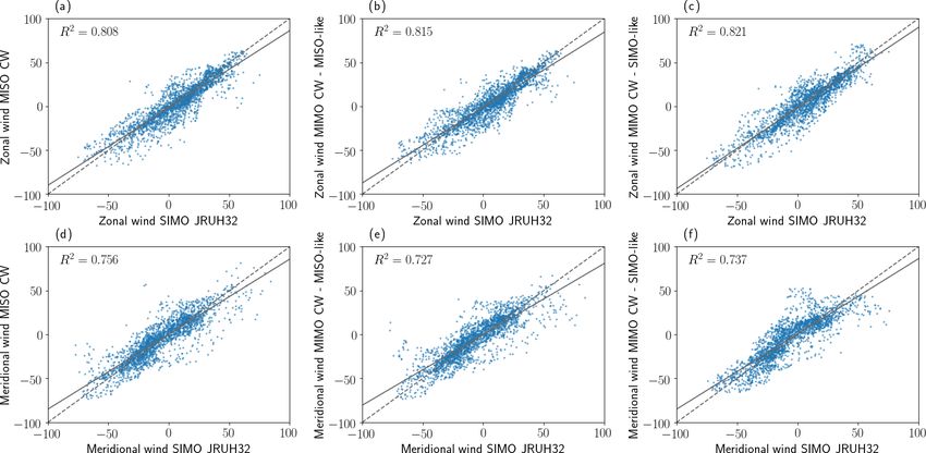
2114                                                                  J. J. Chau et al.: Meteor radar using coherent MIMO

arrival (AOA) of the meteor echoes. The main characteris-         time, polarization, and code. More recently, Urco et al.
tics of the majority of such systems can be found in Hocking      (2019) have used MIMO with time diversity to study po-
et al. (2001) and Holdsworth et al. (2004a).                      lar mesospheric summer echoes (PMSE) in northern Nor-
   To improve the number of detections and also to re-            way. MIMO techniques have been intensively investigated
solve winds inside the illuminated volume, Stober and Chau        and used in the fields of communications, information theory,
(2015) proposed the multi-static and multifrequency ap-           radar remote sensing, and over-the-horizon radar (e.g Telatar,
proach MMARIA (Multi-static, Multifrequency Agile Inves-          1999; Huang et al., 2011; Foschini and Gans, 1998; Frazer
tigations of the Atmosphere). The increased number of de-         et al., 2007).
tections with respect to a monostatic system is mainly due to        In this work we propose novel SMR systems that have
two factors: (1) new and independent detections of the same       emerged from the combination of our previous efforts and
or different meteor trails are obtained in multi-static links,    experiences. This includes the MMARIA concept (multi-
and (2) the effective Bragg wavelength is equal or larger than    static approach), the coded CW approach, statistical inverse-
the monostatic Bragg wavelength, thus allowing the detec-         problems theory (e.g., compressed sensing), and the need to
tion of larger radar cross sections and higher altitudinal cov-   reduce some of the logistical issues experienced in previous
erage (e.g., Stober and Chau, 2015).                              efforts. Our proposed systems make use of transmitting ar-
   The original MMARIA concept consisted of adding                rays in an interferometer-like configuration, with each an-
bistatic interferometric receive-only stations at distances be-   tenna transmitting at the same frequency but with different
tween 60 to 200 km from existing transmitter sites. Vierinen      codes and accompanying receiver stations at distances be-
et al. (2016) extended the concept by adding multiple coded       tween 20 to 200 km, with each station using one or more re-
continuous wave (CW) transmitter stations to be received by       ceiving antennas (multi-static). Upon reception, the signals
the existing network, each of them transmitting at the same       from each transmitter station can be individually decoded
frequency but with different orthogonal codes. Furthermore,       and interferometrically combined to find the angle of depar-
Chau et al. (2017) implemented MMARIA using closely lo-           ture (AOD) of the meteor echoes with respect to the trans-
cated monostatic SMRs in northern Norway, transmitting at         mitter station. This architecture limits most of the deploy-
different frequencies. Preliminary wind field estimations in      ment complexity to a few interferometric transmitter stations
northern Germany using two pulsed transmitters with differ-       while still providing the benefits of existing multi-static and
ent frequencies, two coded CW transmitters, and five receiver     coded CW approaches.
stations have been recently presented by Stober et al. (2018).       We start by describing the typical interferometer configu-
   As shown in Vierinen et al. (2016), the coded CW imple-        rations of existing SMRs, i.e., using a single transmitter and
mentation presents many advantages with respect to tradi-         multiple receivers. Then we present the details of the two
tional pulsed applications. Some of these advantages are that     systems that we have tested, both of them having the same
(1) for the same averaged power, the peak power is much           multiple-transmitter geometry. The observations and results
lower (e.g., 500 W instead of 10 kW for a pulsed transmit-        for each system are presented in Sect. 4 and compared with
ter with a 5 % duty cycle), that (2) one could use the same       close-by observations of a standard SMR system. The advan-
frequency on different transmitting antennas with orthogo-        tages and challenges of the proposed systems are discussed
nal codes, as is done in global positioning systems, and that     in Sect. 5, including options for upgrading existing standard
(3) there are none of the range or Doppler ambiguities that       systems and, more importantly, ideas for future networks of
are present in pulsed systems.                                    multi-static SMRs.
   Each of the MMARIA implementations mentioned above
has proven to be challenging to deploy and operate, particu-
larly for routine observations. For example, the Leibniz In-      2   Interferometry in standard specular meteor radars
stitute of Atmospheric Physics (IAP), in conjunction with
the MIT Haystack Observatory, has implemented a coded-            Although SMRs have existed since World War II, they started
CW SMR network in northern Germany on a campaign ba-              to become more useful for atmospheric studies when they
sis. One of the biggest challenges during this project has        were able to measure the AOAs of the detected echoes by
been finding suitable locations for the transmitting stations     using suitable interferometer configurations. Given the large
in terms of security, societal perception of electromagnetic      variability of signal strength of meteor echoes (more than 6
radiation hazards, legal issues, etc.                             orders of magnitude), configurations able to resolve the AOA
   Urco et al. (2018) have shown that coherent multiple input     within the whole sky are needed even when narrow transmit-
(transmitters) and multiple-output (receivers) (MIMO) tech-       ting antennas are used (e.g., Valentic et al., 1997).
niques can be useful for improving imaging and interfero-            Following the notation of Urco et al. (2018), the spatial co-
metric configurations in atmospheric and ionospheric radars.      herence of a target located at (θR , φR ) (elevation and azimuth)
The techniques have been applied to studies of equatorial         in the far-field with respect to the receiver interferometer, il-
electrojet (EEJ) irregularities at the Jicamarca Radio Ob-        luminated by transmitter p located at r p , and received by a
servatory (JRO), using three transmitting diversity schemes:      pair of receivers m and n located at r m and r n , respectively,

Atmos. Meas. Tech., 12, 2113–2127, 2019                                             www.atmos-meas-tech.net/12/2113/2019/
J. J. Chau et al.: Meteor radar using coherent MIMO 2115
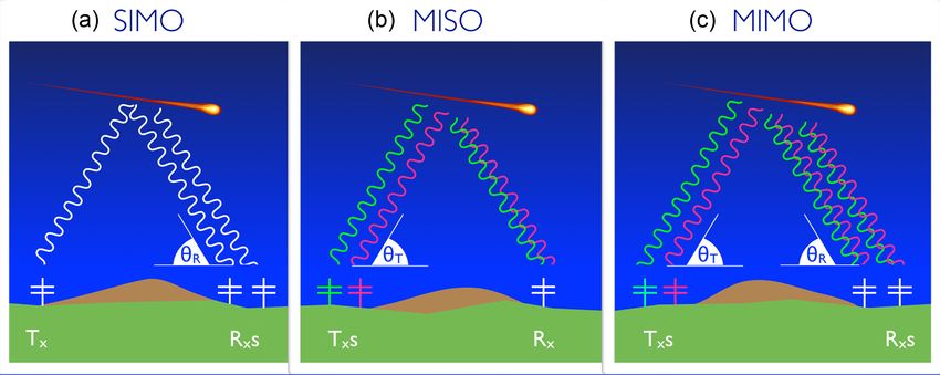
is given by the following equation: ters) single output (receivers). The MISO configuration is de-
picted in Fig. 1b. In this case the spatial coherence of a target
ρ(mnp)(1r mn ) ∝ exp(−j k R 1r mn + j 1φmn ), (1) located at (θT , φT ) (elevation and azimuth) in the far-field
with respect to the transmitter interferometer, illuminated by
where k R is the receiving wavenumber vector with k R =
transmitters p and q located at r p and r q , respectively, and
2(π/λ)[cos θR cos φR , cos θR sin φR , sin θR ], λ is the radar
received by a single receiver m at r m is given by the follow-
wavelength, 1r mn = r m − r n is the separation between re-
ing equation:
ceivers m and n, and 1φmn indicates the instrumental phase
difference between receiver pair (m, n). This expression cor- ρ(mpq)(1r pq ) ∝ exp(−j k T 1r pq + j 1φpq ), (2)
responds to a coherent single-input (transmitter) multiple-
output (receiver) (SIMO) configuration, depicted in Fig. 1a. where k T is the transmitting wavenumber vector with k T =
We are following this nomenclature to be consistent with a 2(π/λ)[cos θT cos φT , cos θT sin φT , sin θT ], 1r pq = r p − r q
more general radar imaging problem when more than one is the separation between the transmitters p and q, and
target is present (e.g., Hysell and Chau, 2006). 1φpq indicates the instrumental phase difference between
For a deterministic target, an estimate of ρ(mnp) given the transmitting pair (p, q). Therefore, the signal direction
by ρ̂(mnp) ∝ vmp vnp ∗ is obtained from the correlation of the with respect to the transmitter k T (AOD) can be obtained
complex voltages at receivers m and n due to transmitter p, from the cross correlation of received signals at antenna m,
vmp , and vnp , respectively. For stochastic targets, ensemble corresponding to transmitters p and q.
averages of this correlation are used (e.g., Urco et al., 2018, By combining the SIMO and MISO configurations, i.e.,
Eq. 2). At least two noncollinear pairs are needed to find the Eqs. (1) and (2), respectively, the spatial coherence expres-
k r vectors (or AOAs). sion for a coherent MIMO configuration is given by the fol-
Currently, the most common configuration in standard lowing equation:
SMRs is the so-called five-antenna Jones interferometer
ρ(mnpq)(1r mn , 1r pq ) ∝ exp(−j k R 1r mn (3)
(Jones et al., 1998). This configuration allows the possibil-
ity of resolving a short baseline for unambiguous determi- − j k T 1r pq + j 1φmn + j 1φpq ).
nation and longer baselines for improving precision in two
Following the notation of Stober and Chau (2015), the dis-
orthogonal directions. The typical antenna separations are
tance of the meteor echo to the transmitter and receiver are
2.0λ and 2.5λ. These pairs of antennas allow a simple al-
denoted by Ri and Rs , respectively.
gebraic solution to the AOA estimation by working with
A sketch of the MIMO configuration is given in Fig. 1c. In
the phase information of Eq. (1) (e.g., Hocking et al., 2001;
the case of MISO and MIMO, the diversity of transmissions
Holdsworth et al., 2004a). However, for improved estimation
is represented in Fig. 1 using two different colors. Recall that
and for logistical purposes, other configurations have been
such diversity, depending on the target and the system, could
used and suggested (e.g., Younger and Reid, 2017). In such
be in time, polarization, or code. In the case of specular me-
cases, e.g., a pentagon configuration or antennas not neces-
teor echoes, polarization diversity is not an option since the
sarily located on a plane, these simple algebraic solutions are
different modes (ordinary or extraordinary) will suffer differ-
no longer applicable. In such configurations, Younger and
ent amounts of group retardation (e.g, Elford, 2004). Based
Reid (2017) have proposed the used of pre-calculated phases,
on the advantages described above, we find CW coding the
while Vaudrin et al. (2018) has proposed a complex fitting
most suitable diversity for our multi-static application. Be-
approach with the inclusion of an uncertainty estimation of
low we discuss other possibilities using time diversity.
the resulting AOAs.
The above expressions are general for both monostatic and
The phase difference between receivers m and n needs to
bistatic configurations. In the case of monostatic, the receiv-
be removed before the AOAs are estimated. Either they are
ing (AOA) and transmitting (AOD) interferometric angles are
measured using common feeding lines or echoes from targets
the same for k R = k T , and the distances are also the same
with well-known locations, or they are empirically estimated
(Ri = Rs ). Note that the expressions are given for far-field
using the expected distribution of underdense specular me-
conditions with respect to each interferometer, i.e., the sepa-
teor echoes (e.g., Valentic et al., 1997; Hocking et al., 2001;
ration between interferometer antennas is much smaller than
Holdsworth et al., 2004b; Lau et al., 2006; Chau et al., 2008;
the distance to the meteor echo, |1r mn |
Rs and |1r pq |
Chau and Clahsen, 2019).
Ri for the receiver and transmitter interferometers, respec-
tively. In other words, MIMO provides the ability to “steer”
3 Experiment configurations using multiple the transmit beam on reception (in software), therefore pro-
transmitters viding the ability to maximize the transmit power incident on
each meteor trail present in the field of view.
A simple way to understand the benefits of coherent MIMO To implement our two multi-static multiple transmitter
configurations is by presenting the interferometric expres- systems, we have used a transmitter array in Kühlungsborn
sion of a MISO configuration, i.e., multiple input (transmit- and a receiver array in Neustrelitz (located ∼ 123 km from
www.atmos-meas-tech.net/12/2113/2019/ Atmos. Meas. Tech., 12, 2113–2127, 2019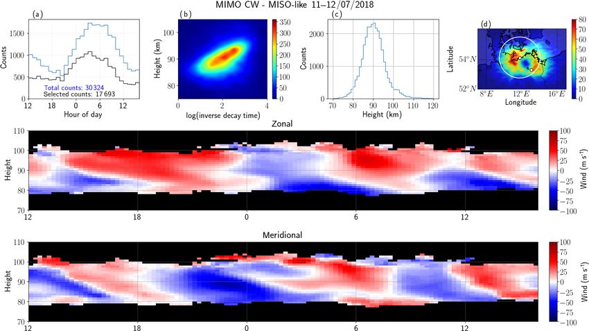
2116                                                                             J. J. Chau et al.: Meteor radar using coherent MIMO

Figure 1. A sketch representing three types of SMR systems: (a) the classic system of using a single transmitter and interferometer on
reception (Rx s) (SIMO), (b) a proposed system using multiple transmitter (Tx s) in interferometer mode at transmission and a single receiver
(MISO), and (c) similar to (b) but with interferometry on reception (MIMO). In the case of MISO and MIMO, the transmitter waves forms
are indicated with different colors, representing different diversity (different codes in our case). Note that elevation angles are measured with
respect to the transmitter (θT , AOD) and/or receiver (θR , AOA).

Kühlungsborn). At transmission a five-antenna 2.45λ equi-                  4     Results
lateral pentagon configuration using a linear polarization
was used. Different simultaneous orthogonal pseudorandom                   The data quality of our proposed systems is compared qual-
coded CW sequences were used on each transmitting an-                      itatively and quantitatively (when relevant) to observations
tenna. The sequence was repeated every 10 ms. On reception,                made with a standard monostatic SMR located in Juliusruh
we used a five-antenna Jones configuration using circularly                in northern Germany (54.63◦ N, 13.37◦ E). The main opera-
polarized antennas. Instead of the traditional 2.0λ and 2.5λ               tional parameters of the Juliusruh radar are shown in Table 1.
spacings, 1.0λ and 1.5λ spacings were used. Such a config-                 Following the nomenclature above, these observations are la-
uration has been successfully implemented at the Alta SMR                  beled SIMO-pulsed.
in northern Norway. In the first implementation we used all                   Figure 2 shows selected measurements of basic parameters
five transmitting antennas and only one receiving antenna                  obtained on 11–12 July 2018 for the Juliusruh SMR: (a) time
(MISO-CW). In the second implementation we use all five                    histogram, (b) 2-D histogram of altitude vs. inverse of me-
receiving antennas (MIMO-CW).                                              teor decay time (in linear scale), (c) altitude histogram, and
   The main experimental parameters of each system can be                  (d) 2-D histogram of latitude vs. longitude (in linear scale).
found in Table 1. For completeness, we are also including the              The total number of good counts are indicated in the time
parameters of the monostatic system located in Juliusruh that              histogram plot in blue, while the number of detections with
is used below as a reference. Note that all multiple transmit-             zenith angles less than 60◦ is indicated in black. In this par-
ter experiments have been performed with customized trans-                 ticular campaign, close to 19 000 useful detections were ob-
mitter and receiver hardware and software developed and in-                tained. In previous years for similar days, close to 24 000 me-
tegrated at IAP in collaboration with colleagues from MIT                  teors were observed using 30 kW peak power. In addition,
Haystack Observatory and the UiT Arctic University of Nor-                 zonal and meridional winds in 1 h and 2 km bins are shown
way. At transmission, five CW Hilberling linear transmitters               in the second and third rows, respectively. These winds have
were used, and the wave forms generated on a PC and com-                   been obtained with those detections within the white circle
municated to the transmitters by USRP-N200 units. On re-                   in Fig. 2d (i.e., with zenith angles less than 60◦ ). These ob-
ception, multiple USRP-N200 units were also used. All the                  servations are typical of the midlatitude mesosphere during
units were independently synchronized to the global refer-                 summer months (e.g., Hoffmann et al., 2010).
ence clock using a Trimble Thunderbolt GPS disciplined os-                    The latitude vs. longitude 2-D histogram are plotted over a
cillator (GPSDO). Currently, none of these coded CW ex-                    geographic map. The locations of the transmitter and receiver
periments could be implemented by existing commercially                    sites are indicated with white solid circles, in this case the
available SMR systems.                                                     same location. Note that Juliusruh is located 118 and 146 km
   In the next section, we present the preliminary results of              from Kühlungsborn and Neustrelitz sites, respectively.
each system and some details of the decoding process. The
specific details of the applied decoding processes in this work            4.1    MISO-CW results
and those that are currently being improved will be given in
a separate paper.                                                          In this section we present the results of the MISO-CW sys-
                                                                           tem that were obtained using the transmitter pentagon con-

Atmos. Meas. Tech., 12, 2113–2127, 2019                                                        www.atmos-meas-tech.net/12/2113/2019/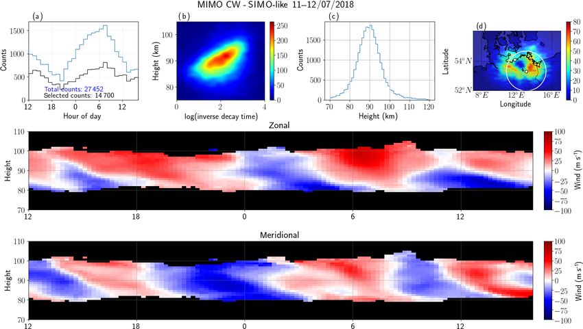
J. J. Chau et al.: Meteor radar using coherent MIMO                                                                                 2117

Table 1. Parameters for each SMR configuration.

                          Parameter               SIMO-pulsed            MISO-CW                 MIMO-CW
                          Frequency               32.55 MHz              32.0 MHz                32.0 MHz
                          Transmitters (Tx s)     1                      5                       5
                          Tx configuration        1                      Pentagon                Pentagon
                          Peak power (each)       15 kW                  400 W                   400 W
                          Duty cycle              4.4 %                  100 %                   100 %
                          Inter pulse period      1.6 ms                 N/A                     N/A
                          Pulse type              Coded pulsed           Coded CW                Coded CW
                          Pulse width             70 µs                  N/A                     N/A
                          Baud width              10 µs                  10 µs                   10 µs
                          Code length             7                      1000                    1000
                          Code type               Barker                 Pseudorandom            Pseudorandom
                          Tx coordinates          13.3◦ E, 54.6◦ N       11.77◦ E, 54.12◦ N      11.77◦ E, 54.12◦ N
                          Receivers (Rx s)        5                      1                       5
                          Rx Polarizations        1                      1                       1
                          Rx configuration        Jones                  N/A                     Jones
                          Rx sampling             10 µs                  10 µs                   10 µs
                          Rx coordinates          13.3◦ E, 54.6◦ N       13.071◦ E, 53.33◦ N     13.071◦ E, 53.33◦ N
                          Date of experiments     11–12 July 2018        11–12 July 2018         11–12 July 2018
                          Tx / Rx separation      0                      122.8 km                122.8 km

Table 2. Summary of SMR implementations. Only detections with zenith angle with respect to the reference that are smaller than 60◦ are
included under “selected counts”.

              Technique                    Number of     Number of          Synthetic      Interferometric    Total    Selected
                                          transmitters    receivers       receivers per    solution          counts     counts
                                                                             receiver
              SIMO-pulsed                           1                5          1          AOA               19 000     14 500
              MISO-CW                               5                1          5          AOD               27 300     15 700
              MIMO-CW MISO-like                     5                1          5          AOD               30 000     17 700
              MIMO-CW SIMO-like                     1                5          1          AOA               27 400     14 700

figuration described above and one circularly polarized re-                to each transmitting antenna are obtained for each detected
ceiving antenna. The decoding process was done on signals                  meteor. More details and discussion of the techniques imple-
from one receiving antenna using a compressed sensing ap-                  mented here and those being developed will be given in a
proach on the complex raw voltages. Following a more com-                  separate paper.
mon radar terminology, our procedure combines a matched                       Figure 3 shows an example of range time intensity (RTI)
filter estimator (MFE) and a maximum likelihood estimator                  from a MISO-CW system obtained on 12 July at 05:09 UT.
(MLE). The MLE is used to detect the strong echoes, whose                  The decoded signals of five synthetic receivers correspond-
signals are then removed from the complex voltages. After                  ing to all five transmitters and one physical receiving antenna
this initial identification and removal, an MFE is applied to              have been incoherently integrated. Note that more than 30
go after the remaining medium to weak echoes. In both cases,               specular meteor echoes are observable with the naked eye,
the time and range location of the echoes is obtained. Finally             along with echoes from an airplane.
a minimum least-squares-error estimator is used to estimate                   An identification process based on the works of Hocking
the complex voltages of echoes at the pre-detected positions               et al. (2001) and Holdsworth et al. (2004a) was applied to
(time and range). In the case of a single transmitter, the MLE             the complex voltages of the detected events. In this process
results could be equivalent to the results of an inverse fil-              we determine, among other parameters, total range detec-
ter, depending on the code selected. Our implementation is                 tion, Doppler frequency, AODs, correlation time, detection
a modified version of the Generalized Orthogonal Matching                  time, etc., of each meteor echo. Namely, the AOD is ob-
Pursuit algorithm (Wang et al., 2012). Note that as a result of            tained from the cross correlation of the complex voltages
this processing, five different complex signals corresponding              corresponding to different transmitting antennas, while the

www.atmos-meas-tech.net/12/2113/2019/                                                          Atmos. Meas. Tech., 12, 2113–2127, 2019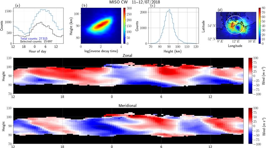
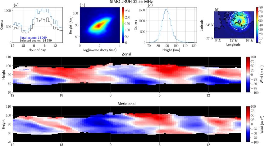
2118                                                                            J. J. Chau et al.: Meteor radar using coherent MIMO

Figure 2. MLT observations with a monostatic SMR system at Juliusruh on 11 July 2018. The first row shows a (a) time histogram, (b) 2-D
histogram of altitude vs. inverse decay time (log scale) color-coded in linear scale, (c) altitude histogram, (d) 2-D histogram of latitude vs.
longitude (linear scale). The zonal and meridional winds in bins of 1 h and 2 km are presented in the second and third rows, respectively.
Note that the region of fewer counts in (d) is over the radar site.

Doppler and correlation times are obtained from the aver-                 verse decay histograms are also in good qualitative agree-
aged autocorrelation. The AOD estimation was done using                   ment with the SIMO-pulsed results, and the expected, small
a combination of beam forming and a complex fitting ap-                   differences can be attributed to the small phase offsets and
proach (e.g., Vaudrin et al., 2018; Chau and Clahsen, 2019).              the different Bragg wavelengths that were excited. Note that
Given the relatively long baselines of the pentagon config-               the circle in Fig. 4d denotes the area of detection with zenith
uration, the altitude information was also used to remove an-             angles that are smaller than 60◦ with respect to the transmit-
gular ambiguities on low-elevation echoes.                                ter, which were used to estimate the zonal and meridional
   Based on the AODs, the detection range, the location of the            winds.
transmitter and receiver sites, the Bragg vectors, and incident
and scattering ranges were calculated (e.g., Stober and Chau,
2015, Eq. 1). AODs were obtained using Eq. (2). Further-                  4.2    MIMO-CW results
more, the zonal and meridional winds were estimated for the
same bins used for the standard Juliusruh system shown in                 Now we present the results for the MIMO-CW system us-
Fig. 2 after calculating Bragg vectors and the Doppler shifts             ing five linearly polarized transmitters at Kühlungsborn and
(e.g., Chau et al., 2017, Eq. 1).                                         five circularly polarized receivers at Neustrelitz. After apply-
   The resulting parameters of the MISO-CW system are                     ing the same decoding process used in the MISO-CW system
shown in Fig. 4 in a similar manner to Fig. 2. The salient                above for each transmit–receive pair, 25 synthetic receiving
features of these results are (a) the wind, time, and altitude            channels are obtained. Recall that for each receiving antenna
histograms are in excellent qualitative agreement with the                the complex voltages corresponding to each transmitting an-
corresponding Juliusruh results (i.e., Fig. 2); (b) the number            tenna is obtained. Figure 5 shows the RTI obtained after in-
of detected meteors is about 27 000 total with about 15 500               coherently integrating the signals of all 25 synthetic receiver
selected with zenith angles less than 60◦ ; and (c) the 2-D lat-          channels for the same time used in Fig. 3. Given that more
itude vs. longitude histograms show the expected elliptical               independent receiver signals are used, the noise variance is
distribution has its foci at the receiver and transmitter sites,          reduced, allowing us to observe more specular meteor echoes
indicated with small white circles. The 2-D altitude vs. in-              (more than 45).

Atmos. Meas. Tech., 12, 2113–2127, 2019                                                       www.atmos-meas-tech.net/12/2113/2019/
J. J. Chau et al.: Meteor radar using coherent MIMO                                                                                      2119

Figure 3. An example of a range–time intensity plot obtained on 12 July 2018 at 05:09 UT with MISO-CW. More than 30 specular meteor
echoes can be observed, in addition to airplane detection. Note that total range is used, i.e., the range from the transmitter to the echo plus
the range from the echo to the receiver.

   At this point we could have proceeded by solving the lo-               given that only one transmitter is used, the number of counts
cation of the meteor echoes using all 25 antennas at the same             is slightly fewer than MIMO-CW MISO-like: ∼ 27 000 to
time, i.e., using Eq. (). In principle, this is doable and it would       14 700 instead of ∼ 30 000 to 17 700 for the total and se-
require converting all the measurements to a common ref-                  lected counts, respectively. Other salient differences with re-
erence (e.g., the center of the Earth) and performing beam                spect to MIMO-CW MISO-like are (a) the observed specular
forming from two different observing centers. To simplify                 meteor echoes close to 70 km and above 110 km and (b) the
the presentation of the MIMO results, we process subsets of               different shape of the 2-D latitude–longitude histogram. The
the 25 synthetic receivers in MISO-like and SIMO-like con-                former might be due to small remaining phase calibration is-
figurations; i.e., interferometric solutions with respect to the          sues or small imperfections in the geometry of the receiving
transmitter and receiver using Eqs. (2) and (1), respectively.            antennas, while the latter is related to the different interfero-
We are leaving the use of all 25 receiving signals simultane-             metric configuration and location. For example, at Kühlungs-
ously, i.e., Eq. (), for a future effort.                                 born there are some small hills to the south, causing different
   Figure 6 shows the results of the MIMO-CW system but                   transmit and receive propagation paths, particularly at very
processed in a MISO configuration (MIMO-CW MISO-like),                    low elevation angles.
using the information of the five transmitters in only one                   In order to have a quantitative comparison, in Fig. 8 we
physical receiving antenna to obtain the AODs, Doppler                    present scatterplots of the zonal and meridional wind com-
shift, total range, and diffusion time. The results are in ex-            ponents using SIMO-pulsed (i.e., SIMO JRUH32) as a ref-
cellent qualitative agreement with the results of MISO-CW,                erence for MISO-CW (first column), MIMO-CW MISO-
as expected since they used practically the same informa-                 like (second column), and MIMO-CW SIMO-like (third-
tion. The main difference is the increased number of detec-               column). Despite the different sampling volumes, the winds
tions (∼ 30 000 and 17 700 instead of ∼ 27 300 and 15 700                 from all three configurations are highly correlated with the
for the total and selected counts, respectively). This increased          Juliusruh winds, presenting Pearson correlation coefficients
number is expected due to the increased number of synthetic               between 0.72 and 0.82. In the case of the other parameters,
receivers used for detection (25), which in turn reduces the              e.g., altitude distribution or altitude vs. inverse decay time
noise variance.                                                           distributions, we have not done a quantitative comparison
   The results of MIMO-CW processed in a SIMO config-                     since the effective Bragg wavelengths are different between
uration (MIMO-CW SIMO-like), using the information of                     the monostatic and multi-static links. Again, by looking at
only one transmitter in all five physical receiving antennas,             panels (b) and (d) in Figs. 2, 4, 6, and 7 the resulting distri-
are shown in Fig. 7. Qualitatively, these results also com-               butions are in excellent qualitative agreement.
pare very well to the Juliusruh results (Fig. 2). However,

www.atmos-meas-tech.net/12/2113/2019/                                                        Atmos. Meas. Tech., 12, 2113–2127, 2019
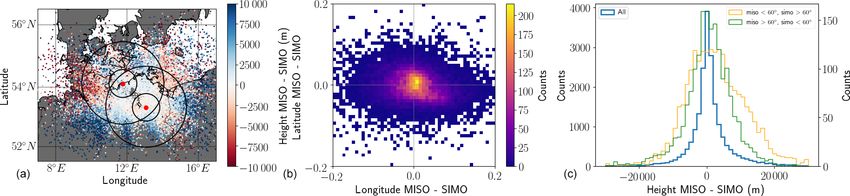
2120                                                                           J. J. Chau et al.: Meteor radar using coherent MIMO

Figure 4. Similar to Fig. 2 but for the MISO-CW system, i.e., the signals of five synthetic receivers have been incoherently integrated. The
transmitter and receiver sites are indicated with small white circles in (d). Note that the region of fewer counts in (d) is over the midpoint of
the receiver and transmitter sites.

   In Fig. 9, we compare the echo location obtained with                   tion variations at low elevations. Note that larger altitude dif-
MIMO-CW MISO-like and MIMO-CW SIMO-like analy-                             ferences in Fig. 9c are shown for echoes occurring further
ses. The left panel shows the simultaneous meteor locations                from Neustrelitz and closer to Kühlungsborn (yellow curve
taken from both systems and color-coded with altitude differ-              in Fig. 9c) than from echoes closer to Neustrelitz and fur-
ences. The larger (smaller) circles represent the loci of 60◦              ther from Kühlungsborn (green curve). This difference re-
(30◦ ) zenith angles with respect to each station. Figure 9c               sults from the Jones configuration used in Neustrelitz that
shows a 2-D histogram (in linear scale) for latitude difference            has smaller baselines than the pentagon configuration used in
vs. longitude difference. In general, both approaches provide              Kühlungsborn. As mentioned above, combining all 25 syn-
practically the same horizontal position. The observed vari-               thetic receivers would provide one single solution as long as
ances in longitude and latitude are mainly due to statistical              the MIMO system is well phase calibrated in both transmis-
uncertainties of the AODs and AOAs that are dependent on                   sion and reception and the antenna locations are well known
their corresponding interferometer configuration, signal-to-               with respect to a single reference, e.g., the Earth’s center.
noise ratio, and elevation angle (e.g., Holdsworth, 2005; Vau-
drin et al., 2018).
   The altitude difference for common detections is shown in               5   Discussion
Fig. 9c for (1) all common detections (blue), (2) for MISO
detections lower than 60◦ at zenith and SIMO detections                    A summary of the basic parameters for the different im-
greater than 60◦ at zenith (yellow), and (3) for SIMO detec-               plementations presented in this work, including number of
tions less than 60◦ zenith and MISO detections greater than                transmitters, number of receivers, number of synthetic re-
60◦ zenith (green). The y axis on the left corresponds to the              ceivers per physical receiver, and counts, is shown in Ta-
blue curve, while the right axis corresponds to the yellow and             ble 2. Our preliminary results confirm that our novel SMR
green results.                                                             MIMO systems are suitable solutions to study the MLT at-
   In the case of altitude, the majority of echoes present a               mospheric dynamics with multi-static geometries, e.g., me-
relatively narrow distribution. The larger altitude variances              teor counts using one transmitter station can be increased by
are due to a mix of statistical uncertainties, small imperfec-             adding multiple single-antenna receiver stations. However,
tions in the antenna geometries, and effective phase calibra-              the SMR MIMO systems are not without their challenges.

Atmos. Meas. Tech., 12, 2113–2127, 2019                                                        www.atmos-meas-tech.net/12/2113/2019/
J. J. Chau et al.: Meteor radar using coherent MIMO                                                                                   2121

Figure 5. Similar to Fig. 3 but for MIMO-CW system, i.e., the signals of 25 synthetic receivers have been incoherently integrated. More than
45 specular meteor echoes can be observed, in addition to an airplane detection.

5.1     Challenges                                                         In the case of multi-static systems, time synchronization,
                                                                        frequency coherence, and time stability are key to the perfor-
5.1.1    Implementation                                                 mance of the proposed systems. In our case we have selected
                                                                        code sequences that are repeated every 10 ms, and by using
As mentioned above, the implementation of our proposed                  the one pulse per second from GPS receiver units, time syn-
systems, i.e., MIMO with coded CW diversity, are currently              chronization between systems is possible within a few tens
not possible with commercially available SMR systems, ei-               of nanoseconds precision.
ther due to hardware or software limitations. Therefore, the
realization and implementation of what we propose would                 5.1.2    Computation
require major upgrades to existing systems or in-house im-
plementation of software-defined radar procedures like those            The filtering and decoding required to process many chan-
implemented in this work, accompanied with some devel-                  nels of CW-coded links is not a trivial operation and can
opments in hardware (e.g., very-high-frequency (VHF) CW                 be computationally demanding. However, the implementa-
transmitters or a pulsed transmitter with large duty cycles).           tion can be done nowadays on personal computers and be
Use of multiple sequences of pseudorandom large codes at                run much faster than the acquisition time. In the end, the
transmission and the corresponding continuous sampling on               problem is reduced to a statistical inverse problem, and as
reception are a couple of challenges with currently commer-             such, depending on the application and the environment, dif-
cially available SMRs.                                                  ferent optimal procedures are possible. For example, one can
   We have decided to test the MIMO concept using coded                 employ a maximum likelihood estimator, zero forcing, min-
CW, which in practice is a form of spread spectrum, given               imum mean-square error, or compressed sensing, to name
the advantages described in the introduction and in Vierinen            a few possibilities (e.g., Vierinen et al., 2016; Klein et al.,
et al. (2016). However, MIMO implementations using time                 1996; Jiang et al., 2011; Strohmer and Friedlander, 2009;
diversity in pulsed systems might be possible, particularly if          Gao et al., 2017). In this work we have used a compressed
the separation between pulses is relative small. For example,           sensing approach, given the natural sparsity of specular me-
a sequence of pulses of a few microseconds wide and with a              teor echoes.
few microseconds of separation between them, i.e., staggered
pulses, might also work. Such a scheme can be considered                5.1.3    Self noise
a subset of our proposed coded CW, where the code con-
sists of −1, 0, and 1 values instead of just −1 and 1. Other            In terms of signal-to-noise ratio (SNR), from the fact that we
groups might try to implement this or other options if they             are transmitting different codes on the same frequency band-
find MIMO attractive to their studies.                                  width, one would expect a degradation of SNR, particularly if

www.atmos-meas-tech.net/12/2113/2019/                                                      Atmos. Meas. Tech., 12, 2113–2127, 2019
2122 J. J. Chau et al.: Meteor radar using coherent MIMO Figure 6. Similar to Fig. 4 but for the MIMO-CW system, applying a MISO-like analysis. Figure 7. Similar to Fig. 4 but for the MIMO-CW system, applying a SIMO-like analysis. Atmos. Meas. Tech., 12, 2113–2127, 2019 www.atmos-meas-tech.net/12/2113/2019/
J. J. Chau et al.: Meteor radar using coherent MIMO                                                                                         2123

Figure 8. Scatterplots of zonal and meridional wind components using the monostatic values as a reference (SIMO-JRUH32) for MISO-CW
(a, d), MIMO-CW MISO-like (b, e), and MIMO-CW SIMO-like (c, f). The Pearson correlation coefficients are indicated on each scatterplot.

Figure 9. Comparisons of MIMO-CW MISO-like and MIMO-CW SIMO-like: (a) latitude and longitude distributions color-coded with
altitude differences, (b) 2-D histograms of differences in latitude and differences in longitude color-coded on a linear scale, and (c) histograms
of altitude difference using all common detections (using left y axis). In (c) we also show the altitude difference histograms for MISO zenith
angles lower than 60◦ and SIMO zenith angles greater than 60◦ (yellow), as well as for MISO zenith angles greater than 60◦ and SIMO
zenith angles less than 60◦ (green) using the right y axis. The loci of 30◦ and 60◦ zenith angles, with respect to each site, are indicated with
black circles in the left panel.

conventional codes and decoding are used. However, the se-                 5.1.4    Cost
lection of nearly orthogonal pseudorandom codes, combined
with advanced signal processing and statistical inverse prob-
lems theory, make such expected SNR degradation manage-                    To facilitate the discussion about costs, we compare two
able. Increasing the code length to a maximum within sig-                  multi-static systems: one using SIMO and one using MISO.
nal coherence and time resolution constraints allows maxi-                 The SIMO system would consist of a single transmitter sys-
mization of the SNR when analyzing links individually. In                  tem with 25 kW peak power and 10 % duty cycle and three
that case, it is most crucial to ensure that the codes sent by             receiving stations, each with five-antenna interferometry ca-
each transmitter are uncorrelated at zero lag because mete-                pability. The MISO system would consist of a single trans-
ors will always appear with zero relative lag between links                mitter station with five 500 W CW transmitters with the same
from the same transmission site. Given the sparse nature of                interferometer geometry as the receivers in SIMO and three
SMR echoes, it is also possible to analyze all of the links                single cross-polarized antenna located at the same places as
collectively using compressed sensing approaches and min-                  the receivers in SIMO. In terms of transmitter costs, given
imize the effect of cross talk even further. More details on               that the average power is similar, the costs are expected to
these arguments will be presented in a separate paper.                     be similar. In the case of SIMO, one pulse generator will be
                                                                           needed, while for MISO five pulse generators are needed.

www.atmos-meas-tech.net/12/2113/2019/                                                          Atmos. Meas. Tech., 12, 2113–2127, 2019
2124 J. J. Chau et al.: Meteor radar using coherent MIMO
On reception, the amount of hardware and space is signifi- a given network, could integrate an engaging display of real-
cantly reduced for MISO compared to SIMO, one antenna, time MLT winds and meteor detection maps, which would
two receiving channels, and 5 m × 5 m of area instead of five be particularly attractive to the general public during meteor
antennas, five receiving channels, and 50 m × 50 m, respec- showers.
tively. Taken together, we expect the costs to be roughly sim-
ilar, although if more links are desired, the incremental cost 5.2.2 MIMO-CW
of MISO is much lower than SIMO. A summary of these
values is shown in Table 3. Note that in this simple analysis, Our second proposed system, MIMO-CW, would be the
research and development costs are not included. equivalent of a luxury model in a commercial line of prod-
ucts. In terms of costs, it would be the most expensive since
5.2 Advantages we would not have the same benefit of having simple receiver
stations, as is the case with MISO-CW. However, in terms
In general, we think that these challenges are worth the ben- of performance (number of detections, uncertainties in es-
efits that they enable. The field of telecommunications also timates, quality of measured parameters, separation between
faced similar challenges, but in the end the advantages of sites, etc.) it would be the best of the two options for the same
MIMO techniques (e.g., amount of information on improved geometry. Just from the detection point of view, one increases
channels) were much greater than the implementation costs the number of incoherent integrations from 5 to 25, allow-
and small losses in SNR (e.g., Telatar, 1999; Zheng and ing the detection of weaker echoes. In terms of meteor loca-
Tse, 2003). As mentioned in the introduction, the proposed tion, AODs can be independently measured with respect to
MIMO systems arose from the difficulty of building out a the transmitters, and AOAs with respect to the receiver sites,
multi-static SMR network with multiple transmitter sites and by using the information of one receiver and all the transmit-
multiple interferometric receiving stations. The original idea ters (MISO-like) and by using the information of one trans-
of adding receiving antennas with interferometry capabil- mitter and all the receivers (SIMO-like), respectively, as we
ity to existing transmitter sites (Stober and Chau, 2015), al- have done in this work. For relatively long links, detections
though much cheaper than a single monostatic SMR station, have a larger elevation angle with respect to one of the sites
in practice has not been easy to implement, mainly due to than the other; therefore, AOA and AOD estimates will have
logistical problems (area, fence, security, etc.). Our second less uncertainty (e.g., Hocking, 2018) with a MIMO system
parallel approach was to add single antenna coded CW trans- than with either a MISO or SIMO system. As far as we know,
mitters to existing receiving arrays. The main challenge here this is the first time such simultaneous independent measure-
has been dealing with societal perception of the dangers as- ments have been done with SMRs.
sociated with a VHF transmitter near an occupied area. After Larger uncertainties in altitude are expected for low el-
a couple of years of experience exploring different options evation angle detections (e.g., Hocking, 2018; Holdsworth,
to realize the benefits of spatial information and additional 2005; Vaudrin et al., 2018). Moreover, larger uncertainties
counts from applying multi-static SMR approaches, we have are expected for configurations with shorter antenna base-
come to strongly believe that the MISO-CW and MIMO-CW lines (e.g., Holdsworth, 2005; Younger and Reid, 2017; Vau-
configurations provide the best path forward to implement drin et al., 2018). Therefore, the altitude differences of com-
multi-static SMR networks. mon detections in Fig. 9 are expected. Besides the statistical
uncertainties, we have found that the differences are also sen-
5.2.1 MISO-CW sitive to the precision of the interferometer geometry. These
types of uncertainty are also expected in conventional SMR
In the case of the MISO-CW, once the transmitter with in- pulsed systems. AOA and AOD uncertainties for relatively
terferometer capability is installed, adding more multi-static low elevation angles could be reduced by employing larger
links is relatively trivial. Each receiving station only requires baselines and more receiving antennas (e.g., Holdsworth,
a small area, and does not need permission to receive. The 2005) and/or by adding antennas with a significant distance
phase calibration is only necessary at one station: the trans- in the vertical direction, e.g., an elevated antenna in the cen-
mitter site. Another scientific potential of MISO-CW is the ter of a pentagon (e.g., Younger and Reid, 2017). In general,
possibility of receiving orthogonal linear (or circular) po- having a good estimate of the AOA uncertainties can be use-
larizations, thereby adding the ability to study polarization ful in the derivation of atmospheric parameters even when
issues in meteor trails due to background electron density, using low-elevation meteor detections, as long as such uncer-
Earth’s magnetic field, and geometry. Although we are still tainties are properly propagated and included in the inversion
at the testing stages, such systems could be installed in many processes.
places (e.g., in schools), and if efforts are placed to reduce As mentioned above, a more robust processing approach
the costs of hardware, deployment of receiving sites could than division into MISO-like and SIMO-like configurations
even be extended to the general public to promote citizen should provide a single meteor location, taking into account
science. Each receiver station, aside from providing data to the geometry and interferometric configurations involved and
Atmos. Meas. Tech., 12, 2113–2127, 2019 www.atmos-meas-tech.net/12/2113/2019/J. J. Chau et al.: Meteor radar using coherent MIMO 2125
the expected statistical uncertainties of AOAs and AODs. As Table 3. Comparisons between a SIMO and a MISO multi-static
shown by Vaudrin et al. (2018), AOA statistical uncertain- system.
ties are not constant and depend on SNR, diffusion time, and
zenith angle. For example, low-elevation high SNR detec- Parameter SIMO Pulsed MISO CW
tions can have a small AOA uncertainty, and therefore also Transmitter sites 1 1
have a small altitude uncertainty, which could be smaller in
that case than for detections with a high elevation angle and Transmitters (Tx s) 1 5
lower SNR. The same arguments apply to AODs. Addition- Tx configuration Single Five-antenna
Polarization Circular Linear or circular
ally, a complete Earth geometry should be integrated into
Peak power (each Tx ) 25 kW 500 W
the full solution when combining all 25 effective channels. Duty cycle 10 % 100 %
In terms of receiver pairs, the full solution (instead of five Pulse type pulsed coded coded CW
effective channels at a time) would increase the number of Pulse generators 1 5
pairs from 10 to 300, 30 times more. Although a MIMO-CW Control computers 1 1
implementation might not be attractive for planning from
Receiving sites 3 3
scratch in terms of logistics, it might be attractive when built
on top of existing receiving systems as in our case. In fu- Receivers (Rx s) 5 2
ture efforts, we plan to implement variants of the approach Rx polarizations 1 1
proposed by Vaudrin et al. (2018) to real data, i.e., by using Rx configuration five-antenna Single
a complex fitting approach, to obtain uncertainties not only Number of Rx s 5 2
in Doppler and correlation time but also in direction cosines Control computers 1 1
Sampling Gated Continuous
and, therefore, in location.
Receiving area 50 m × 50 m 5m×5m
5.3 Comparison to monostatic
Recently Hocking (2018) has used near-worst-case values system where the center is the midpoint between receiver and
of uncertainties and simple geometrical arguments to stress transmitter; instead of a circle, the loci of zero radial veloc-
the potential limitations of bistatic SMR systems. Our com- ity are ellipses with foci at the receiver and transmitter sites;
parison of MIMO-CW MISO-like and MIMO-CW SIMO- and instead of a constant Bragg wavelength equal to λ/2, the
like corroborates some of the warnings stressed, namely the bistatic Bragg wavelength depends on the geometry with the
large uncertainties in AOAs experienced at low elevation an- largest values at the midpoint. Therefore, in monostatic sys-
gles. However, instead of seeing limitations, we would like to tems there are also regions of zero radial velocity, regions of
stress the opportunities of such systems. For example, with small projected velocities (close to overhead), and, of course,
conservative use of detections only at high elevation angles, detections at low-elevation AOAs with relatively large AOA
as is done in existing monostatic systems, multi-static sys- uncertainties. We agree that bistatic geometries add relative
tems deployed at relative short distances (between 60 and complications depending on the separation of the transmitter
200 km, as suggested in previous works) provide a significant and receiver sites, but we want to stress that they are relative
region of additional meteor counts with diverse observing depending on the implementation, the approach used, and the
geometries. Based on the arguments above, different inter- application.
ferometer configurations could be used to decrease the AOA Finally, we also think the MIMO ideas could be applied to
uncertainties at low elevation angles and further increase the pulsed systems and monostatic configurations. Besides the
region of low-altitude uncertainty detections. Specifically, time diversity suggested above, relatively long codes with
Holdsworth (2005) have suggested adding a fourth antenna suitable diversity (orthogonality) could be used. For exam-
to each Jones arm with a baseline of 20λ, and Younger and ple, a monostatic MIMO-pulsed configuration using code di-
Reid (2017) have suggested adding a center antenna to a versity has been used successfully for EEJ imaging at Jica-
pentagon configuration with an altitude of 2.2λ. The com- marca by Urco et al. (2018). This option might be attractive
bination of these options with our proposed MISO-CW sys- for existing systems. In terms of hardware, one would need to
tems would significantly increase the useful area, even when use the receiving antennas as transmitters, upgrade the num-
conservative approaches are used. More sophisticated and ber and type of transmitters to allow pseudorandom coding
aggressive approaches would require a rigorous uncertainty and a relatively long duty cycle, and reduce the number of re-
propagation. ceivers to one or two. Once the decoding is implemented, the
An additional potential limitation of bistatic systems de- rest of the software, including detection, identification, wind
scribed by Hocking (2018) is the use of velocity estimation analysis, etc., would still be useful. Subsequently, adding a
in certain areas, particularly the midpoint between receiver multi-static capability would be much simpler and would al-
and transmitter site. As pointed out by Stober et al. (2018), a low additional counts, different viewing angles, and the spa-
bistatic system can be interpreted as an equivalent monostatic tial information of atmospheric winds.
www.atmos-meas-tech.net/12/2113/2019/ Atmos. Meas. Tech., 12, 2113–2127, 20192126 J. J. Chau et al.: Meteor radar using coherent MIMO
6 Conclusions Author contributions. JLC and JMU conceived the idea and wrote
most of the paper. JMU, JPV, and RAV worked on the detection of
We have introduced and tested novel SMR systems us- the meteors using compressed sensing and contribute with parts of
ing multiple transmitters in an interferometric configuration. the writing. MC worked on the identification and processing of the
Such systems are shown to be good options to study the detected meteors as well as in the generation of most of the figures.
MLT region, particularly if they are used in networks with NP and JT designed and implemented the hardware and software
multi-static configurations. Our first system, MISO-CW, al- needed for the systems employed, and supported the operations.
lows multi-static observations with interferometry (AODs)
by having only one antenna at each receiving site. In the case
Competing interests. The authors declare that they have no conflict
of the MIMO-CW, interferometry is accomplished at both
of interest.
the transmitter (AODs) and receiver sites (AOAs).
In both cases the main atmospheric parameters, includ-
ing the zonal and meridional winds, are in very good qual-
Acknowledgements. This work was partially supported by the
itative and quantitative agreement with measurements con- Deutsche Forschungsgemeinschaft (DFG, German Research Foun-
ducted with a standard monostatic SMR located in Juliusruh. dation) under SPP 1788 (CoSIP)-CH1482/3-1 and by the WATILA
Small differences can be attributed to the slightly different Project (SAW-2015-IAP-1). The authors gratefully acknowledge
observing volumes and the different Bragg wavelengths that the support of an international team from the International Space
were scattered. Science Institute (ISSI-Bern) and discussions within the ISSI Team
We have also presented for the first time two indepen- 410. Some hardware, software, and analysis work at the MIT
dent measurements of the same meteors, as their angular lo- Haystack Observatory was supported by NSF Major Research
cations are resolved from both the transmitter (MISO-like, Infrastructure grant AGS-1626041. Jorge Luis Chau thanks David
AODs) and receiver (SIMO-like, AOAs) sites independently. Holdsworth for the suggestions that improved this paper. We also
thank Claudia and Fred Bauske for letting us run the first proof of
We have shown that the mean differences in horizontal dis-
concept at their house and Kiara Chau for sketching our proposed
tance are relatively small (a standard deviation of a few hun-
systems in Fig. 1.
dred meters). The major differences are observed in altitude,
although any observed large altitude differences are within The publication of this article was funded by the
the statistical uncertainties of the AOAs and AODs and are Open Access Fund of the Leibniz Association.
known and shown to be larger at low elevation angles. More-
over, larger uncertainties are obtained with respect to the re-
ceiver site, where the interferometer used consists of smaller Review statement. This paper was edited by Markus Rapp and re-
baselines than those used at the transmitter site. viewed by two anonymous referees.
The realization of our proposed and tested implementation
required modern hardware practices (e.g., coded-CW) and
advanced signal processing for decoding and detection. After
detection, processes used in standard systems are applicable, References
including identification, AOAs and AODs estimation, wind
estimation, etc. Chau, J. L. and Clahsen, M.: Empirical phase calibration for multi-
We expect to collaborate with academic and industrial static specular meteor radars using a beam-forming approach,
groups that are interested on our proposed systems so that the Radio Sci., https://doi.org/10.1029/2018RS006741, 2019.
Chau, J. L., Hysell, D. L., Kuyeng, K. M., and Galindo, F. R.:
benefits that we envision are implemented and exploited by
Phase calibration approaches for radar interferometry and imag-
other groups. By doing so, we expect that studies of the MLT
ing configurations: Equatorial Spread F results, Ann. Geophys,
region, e.g., MLT gravity waves and turbulence at scales from 26, 2333–2343, 2008.
few kilometers to a few hundred kilometers, can be signifi- Chau, J. L., Stober, G., Hall, C. M., Tsutsumi, M., Laskar,
cantly improved over different parts of the world. F. I., and Hoffmann, P.: Polar mesospheric horizontal di-
vergence and relative vorticity measurements using mul-
tiple specular meteor radars, Radio Sci., 52, 811–828,
Data availability. The parameters of the identified files for the https://doi.org/10.1002/2016RS006225, 2016RS006225, 2017.
MISO, MIMO SIMO-like, and MIMO MISO-like systems are writ- Elford, W. G.: Radar observations of meteor trails, and their inter-
ten in HDF5 format with their respective metadata. In the case of pretation using Fresnel holography: a new tool in meteor science,
Juliusruh SIMO data, the files are written in ASCII, selfexplana- Atmos. Chem. Phys., 4, 911–921, https://doi.org/10.5194/acp-4-
tory, format with extension “mpd”. All the files can be found at 911-2004, 2004.
ftp://ftp.iap-kborn.de/data-in-publications/ChauAMT2019. Foschini, G. J. and Gans, M. J.: On limits of wireless communi-
cations in a fading environment when using multiple antennas,
Kluw. Commun., 6, 311–335, 1998.
Frazer, G. J., Johnson, B. A., and Abramovich, Y. I.: Orthogonal
waveform support in MIMO HF OTH radars, in: 2007 Inter-
Atmos. Meas. Tech., 12, 2113–2127, 2019 www.atmos-meas-tech.net/12/2113/2019/You can also read