OGS Installation manual - Somati system sro
←
→
Page content transcription
If your browser does not render page correctly, please read the page content below
Installation manual
                 OGS

                    Somati system s.r.o., Jihlavská 510/2c, 664 41 Troubsko
3/2019                                      IČ: 29260159, DIČ: CZ29260159
                              tel: +420 547 427 011, www.somati-system.cz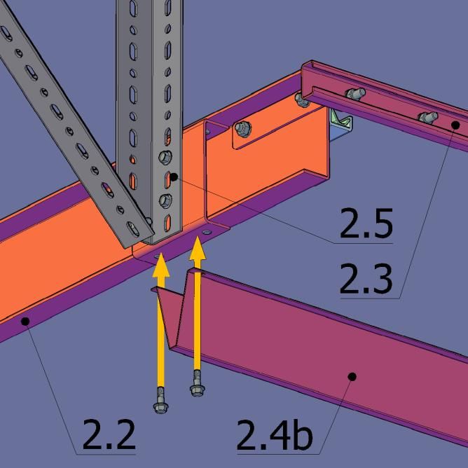
1.   NOTICE BEFORE INSTALLATION .................................................................. 1
         2.   CHECK OF DELIVERY .................................................................................... 2
         3.   TYPES OF OGS ............................................................................................ 10
         4.   CHECK OF CONSTRUCTION READINESS ACCORDING TO THE DRAWING 12
         5.   INSTALLATION OF GUIDES ........................................................................ 13
         6.   INSTALLATION OF BRACKETS .................................................................... 14
           6.1 OGS STANDARD AND HIGH-LIFT...................................................................... 14
           6.2 OGS VERTICAL ................................................................................................ 14
           6.3 OGS LOW-LIFT ................................................................................................ 15
         7. INSTALLATIOn OF ROLLER ........................................................................ 19
           7.1 OGS STANDARD, VERTICAL AND HIGH-LIFT ..................................................... 19
           7.2 OGS LOW-LIFT ................................................................................................ 21
         8. INSTALLATION OF CURVED TRACK............................................................ 22
         9. HORIZONTAL STIFFENERS ......................................................................... 24
         10. HORIZONTAL LATHING .............................................................................. 25
         11. INSTALLATION OF SECTIONS .................................................................... 26
         12. INSTALLATION OF MOTOR ......................................................................... 30
         13. ASSEMBLY OF CARRYING ROPES AND THEIR ADJUSTMENT .................... 31
         14. COMPLETION OF THE INSTALLATION ........................................................ 32

                                                                            Somati system s.r.o., Jihlavská 510/2c, 664 41 Troubsko
3/2019                                                                                              IČ: 29260159, DIČ: CZ29260159
                                                                                      tel: +420 547 427 011, www.somati-system.cz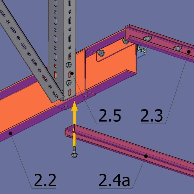
1. NOTICE BEFORE INSTALLATION
    Dear customers,

           we are pleased, you have decided for sectional fire gates from the company Somati
    system s.r.o.
           Please, read the instructions carefully and follow them step by step. You will obtain
    important information on the safe installation and operation of your gates and proper
    maintenance and repairs.
           Professional use and proper maintenance significantly influence the performance and
    serviceability of the gate system. Errors in operating and improper maintenance lead to
    operating malfunctions, which can be normally avoided. Your satisfaction and long-term
    operational safety is ensured only in case of professional use and proper maintenance.

    Important guidelines:

       •   Follow instructions mentioned in this manual.
       •   Improper installation or maintenance of the gate can lead to life-threatening injuries.
           For your own safety, have the installation done by a qualified company.
       •   Transport gate leaves only on a special pallet. During transportation without pallet
           you can damage the gate surface.
       •   These gates open and close vertically. For this reason, make sure that during the
           operation of the gate there are no persons in the area of the gate movement –
           especially children – and no objects blocking movement of the gate.
       •   Use gate system only if it is in perfect technical condition. Malfunction of the gate system
           can lead to life-threatening injuries.
       •   Make sure that during all inspections, repairs and cleaning, the gate system is not
           controlled by a third party.
       •   Do not change or remove any functional parts! This way you can put important safety
           components out of order.
       •   Do not install any additional structural parts. All structural parts are tailor-made and
           fit exactly to each other. Additionally mounted parts can overload the gate structure and
           lead to life-threatening injuries.

    Work equipment:

       •   Use only tools suitable for installation of gate system and appropriate equipment

       Gather all the following work equipment:

       •   Appropriate lifting equipment (forklift truck, crane) for lifting roller and
           placing it on the brackets (watch out for the total weight of the roller men-
           tioned at the installation drawings)
       •   Appropriate lifting platform or scaffolding
       •   Drill
       •   Grinder
       •   Set of spanners
       •   Optical levelling devices
       •   ACCU screwdriver
       •   Screw taps (in case of installation on steel structure)
                                                           Somati system s.r.o., Jihlavská 510/2c, 664 41 Troubsko
                                                                                   IČ: 29260159, DIČ: CZ29260159
                                                                     tel: +420 547 427 011, www.somati-system.cz
1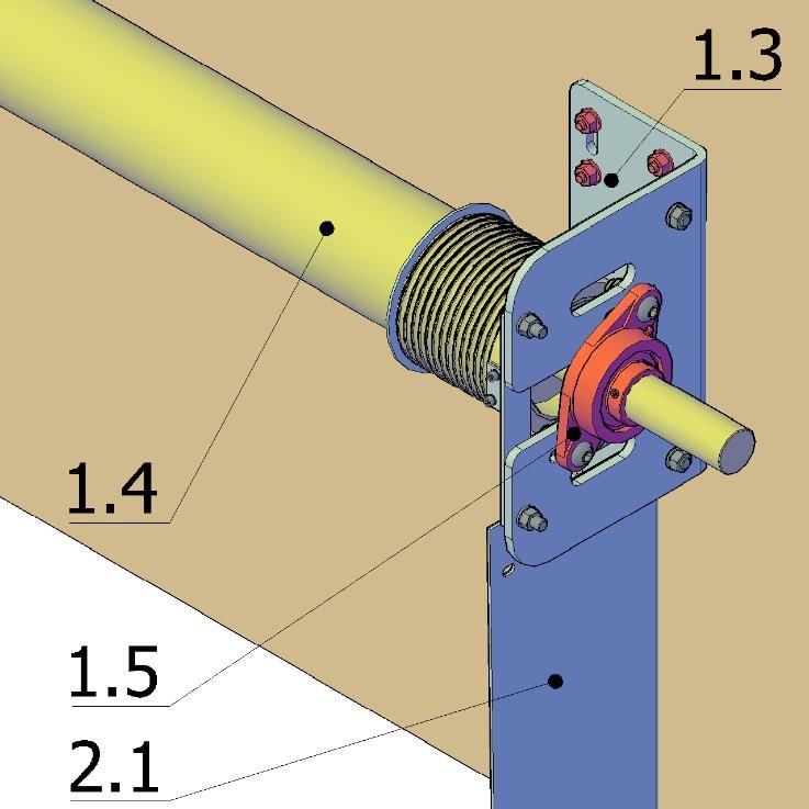
2. CHECK OF DELIVERY
    Before starting the installation, remove the technical drawing and pacing list from the pack-
    aging and make sure that the delivery corresponds to the packing list.

     SET OF MOTOR
           motor bracket

      1.1

            motor (SI, FS, MDF)

      1.2

            winding roller bracket (2 pcs) (not applicable for low lintel)

      1.3

            winding roller including drums

      1.4

            flanged bearing UCFL

      1.5

                                                         Somati system s.r.o., Jihlavská 510/2c, 664 41 Troubsko
                                                                                 IČ: 29260159, DIČ: CZ29260159
                                                                   tel: +420 547 427 011, www.somati-system.cz
2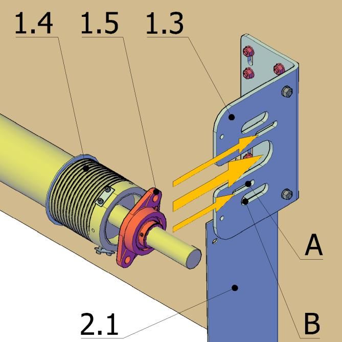
steel wire rope with pressed eyelet

    1.6

    1.7 fasteners

    GUIDES
       side guide with vertical rail (1 pair)

    2.1

          curved rail (1 pair) – not used for vertical OGS

    2.2

          strut - not used for vertical OGS

    2.3

                                                        Somati system s.r.o., Jihlavská 510/2c, 664 41 Troubsko
                                                                                IČ: 29260159, DIČ: CZ29260159
                                                                  tel: +420 547 427 011, www.somati-system.cz
3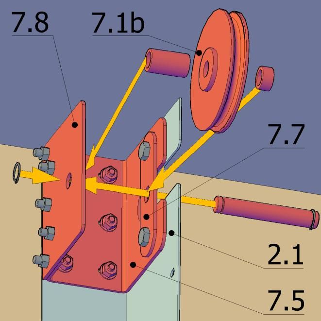
reinforcement (number according to the length of horizontal guidance (not applica-
           ble for vertical OGS)
           a – for gate of width < 4 m            b - for gate of width ≥ 4 m

    2.4

           wind bracing - not applicable for vertical OGS
    2.5

    2.6 fasteners

    HORIZONTAL LATHING
         horizontal lathing

     3.1

     3.2     fasteners

    GATE SECTION
          section without passage door

     4.1

             section with passage door

     4.2

                                                        Somati system s.r.o., Jihlavská 510/2c, 664 41 Troubsko
                                                                                IČ: 29260159, DIČ: CZ29260159
                                                                  tel: +420 547 427 011, www.somati-system.cz
4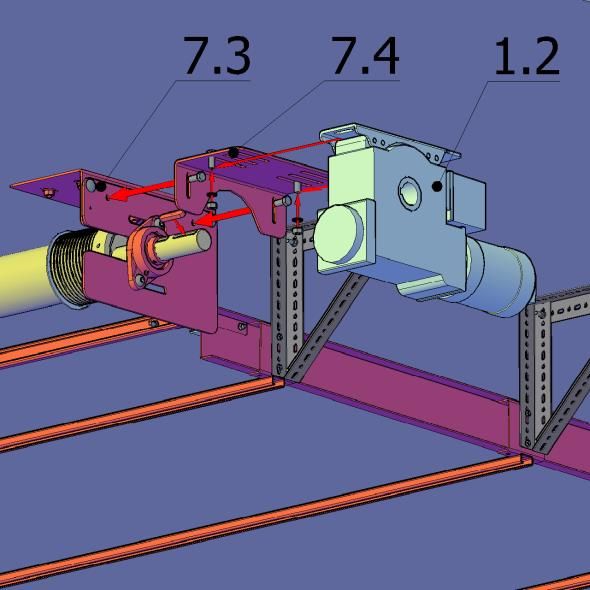
side edges (number of edges = 2x number of sections)

    4.3

          upper edge profile

    4.4

          bottom profile (only for gates with passage door)

    4.5

          upper hinge with pulley

    4.6

          side hinge with pulley

    4.7

                                                    Somati system s.r.o., Jihlavská 510/2c, 664 41 Troubsko
                                                                            IČ: 29260159, DIČ: CZ29260159
                                                              tel: +420 547 427 011, www.somati-system.cz
5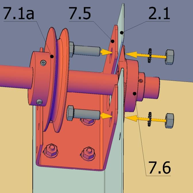
centre hinge

     4.8

           safety brake with pulley

     4.9

    4.10   fasteners

    CONTROL
         control box + installation manual
         FSTRONIC 24                  FSTRONIC DES-FI                TS 970

     6.1

     6.2   cable of motor

    ACCESSORIES FOR GATES WITH LOW LINTEL
         shaft with pulleys
         a – for gates of width ≤ 3 m   b - for gates of width > 3 m (2 pcs)

     7.1

                                                 Somati system s.r.o., Jihlavská 510/2c, 664 41 Troubsko
                                                                         IČ: 29260159, DIČ: CZ29260159
                                                           tel: +420 547 427 011, www.somati-system.cz
6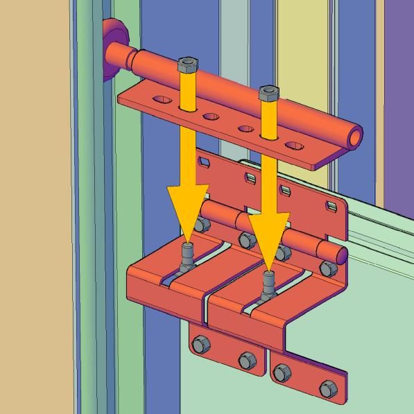
winding roller bracket – ceiling part (2 pcs)

    7.2

          winding roller bracket – side part (2 pcs)

    7.3

          motor bracket - fixing

    7.4

          inserting bracket - J-profile

    7.5

          flanged bearing UCFL (only for gates of width ≤ 3 m) (2 pcs)

    7.6

                                                       Somati system s.r.o., Jihlavská 510/2c, 664 41 Troubsko
                                                                               IČ: 29260159, DIČ: CZ29260159
                                                                 tel: +420 547 427 011, www.somati-system.cz
7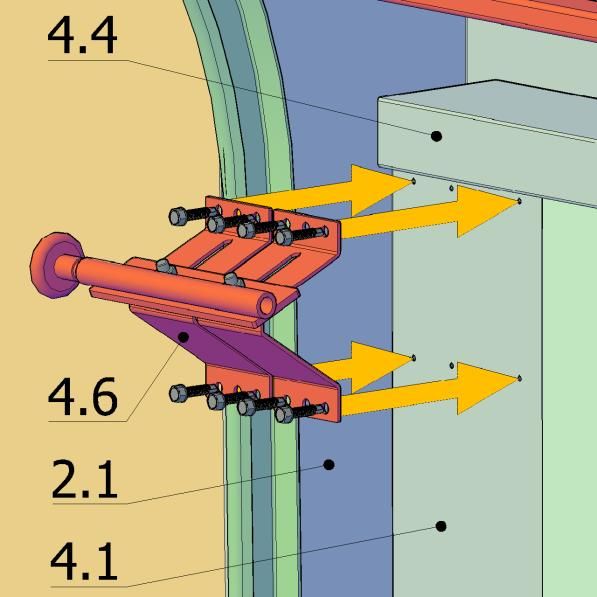
reduction for the shaft mounting (only for gates of width > 3 m) (2 pcs)

    7.7

          additional part of J-profile (only for gates of width > 3 m) (2 pcs)

    7.8

    7.9   fasteners

                                                      Somati system s.r.o., Jihlavská 510/2c, 664 41 Troubsko
                                                                              IČ: 29260159, DIČ: CZ29260159
                                                                tel: +420 547 427 011, www.somati-system.cz
8
OTHER
8.1 additional accessories – according to the order specification
installation material – standard delivery does not include bolts for installation into
supporting structure – possible to order according to the type of supporting structure
(wall, steel structure)
recommended anchor material
wall material brackets guides lathing
wall plug (e.g. Fisher wall plug (e.g.
anchor to concrete
SX) 8x65 mm + Fisher SX) 8x65 mm
concrete M12x110
buttonhead screw + countersunk
(e.g. Hilti HSA)
6x80 mm screw 6x80 mm
8.2
TEX 5,5x45 mm
TEX 6,3x45 mm with
steel structure screw M12x min. 30 with countersunk
hexagon head
head
ceramic wall anchoring with
(Porotherm) threaded rod M12 wall plug (e.g. Fisher wall plug (e.g.
through wall + SX) 8x65 mm + Fisher SX) 8x65 mm
gas-silicate (Ytong)
spreading plates countersunk screw + countersunk
wall from solid threaded rod M12 + 6x80 mm screw 6x80 mm
bricks chemical anchor
example of optional electrical accessories
optional battery module for FSTRONIC DES-FS
8.3
connection box with spiral cable for optical safety edge OSE, including grommet
8.4
Somati system s.r.o., Jihlavská 510/2c, 664 41 Troubsko
IČ: 29260159, DIČ: CZ29260159
tel: +420 547 427 011, www.somati-system.cz
93. TYPES OF OGS
W – opening width H – opening height N - lintel
standard N = 900 mm
vertical N = H + 500 mm
Somati system s.r.o., Jihlavská 510/2c, 664 41 Troubsko
IČ: 29260159, DIČ: CZ29260159
tel: +420 547 427 011, www.somati-system.cz
10high-lift lintel 900mm > N < (H + 500 mm)
low-lift lintel N = 750 mm
All variants can be designed with passage door or without passage door. Passage door must
always open to the wall.
Somati system s.r.o., Jihlavská 510/2c, 664 41 Troubsko
IČ: 29260159, DIČ: CZ29260159
tel: +420 547 427 011, www.somati-system.cz
114. CHECK OF CONSTRUCTION READINESS ACCORDING TO THE
DRAWING
W – opening width H – opening height N - lintel P – floor level
Picture 1
• See dimensions in the enclosed drawings.
• Mark centre of the opening.
• Make a level line on the wall (horizontal line at height 1m above clear floor level).
• If any of the dimensions are bigger than in the documentation, it is not possible to
install the gate.
Somati system s.r.o., Jihlavská 510/2c, 664 41 Troubsko
IČ: 29260159, DIČ: CZ29260159
tel: +420 547 427 011, www.somati-system.cz
125. INSTALLATION OF GUIDES
Side guides are delivered in a set with vertical lathing. Right and left guide install according
to the provided drawings. Standardly the load-bearing structure is anchored through each
second pre-prepared hole and always through the highest and lowest holes. After the
installation put Palusol on the vertical lathing.
Standard distance of guide anchoring from the edge of opening
A – guide
B – vertical lathing
C – rail, mounted on the guide
D – Palusol, glued on the guide after the
installation (e.g. with glue Colgel, Mamut
Glue)
Picture 2
1. Mark on the guides distance 1m from
the bottom edge.
2. Mount left and right guide on the
wall at a distance from the edge of
the opening, indicated in the installa-
tion drawing. Vertical pitch of the an-
chor points must be max. 1 m.
3. Check the correct distance of the
guides by inserting horizontal lathing
between the guides. The lathing
should be tightly attached to the
guides on both sides.
4. Align the guides into the vertical
plane and tighten the anchor mate-
rial.
Picture 3
Somati system s.r.o., Jihlavská 510/2c, 664 41 Troubsko
IČ: 29260159, DIČ: CZ29260159
tel: +420 547 427 011, www.somati-system.cz
136. INSTALLATION OF BRACKETS
6.1 OGS STANDARD AND HIGH-LIFT
standard: N = 900 mm
high-lift: 900mm > N < (H + 500 mm)
The bracket pitch is shown in the en-
closed installation drawing.
Standard bracket distance [1.3] from the
inner edge of the track is 25 mm. The
bracket is mounted just above the guide
[2.1] - standardly: V = 530 mm
- high-lift lintel: V = N - 370 mm
Picture 4
6.2 OGS VERTICAL
N = H + 500 mm
The bracket pitch is shown in the en-
closed installation drawing.
Standard bracket distance [1.3] from the
edge of the track is 25 mm. The bracket
is mounted just above the guide [2.1].
Picture 5
Somati system s.r.o., Jihlavská 510/2c, 664 41 Troubsko
IČ: 29260159, DIČ: CZ29260159
tel: +420 547 427 011, www.somati-system.cz
146.3 OGS LOW-LIFT
width W ≤ 3 m N = 750 mm
For low-lift gates are used guides [2.1] with
cut-out. The inserting bracket [7.5] for
transfer pulley is placed at the top of the
guides. The inserting bracket is anchored to
the wall through the holes in the guide.
Insert shaft with pair of pulleys [7.1a] into
the cut-out of the bracket. The setting
screws on the pulley can be loosened and
the pulley moved so that the bearing [7.6]
can be mounted using two screws with nut
and spring washer. Fix the pulleys in the
correct position in the later stage of the in-
stallation.
Picture 6
Picture 7 Picture 8
Somati system s.r.o., Jihlavská 510/2c, 664 41 Troubsko
IČ: 29260159, DIČ: CZ29260159
tel: +420 547 427 011, www.somati-system.cz
15width W > 3 m N = 750 mm
On inserting bracket [7.5] is mounted addi-
tional part [7.8] and reduction for shaft fix-
ing [7.7] by using screws M12x30. Place
the shaft through the reduction hole, put
on it a short spacer tube, pulley (with bear-
ing) [7.1b], long spacer tube and on the
outside of the additional part [7.8] secure
the shaft with a safety ring.
Picture 9
Picture 10 Picture 11
Somati system s.r.o., Jihlavská 510/2c, 664 41 Troubsko
IČ: 29260159, DIČ: CZ29260159
tel: +420 547 427 011, www.somati-system.cz
16Picture 12
On the ceiling, mark the position of the ceiling parts of the winding roller brackets
[7.2]. Distance X from the wall is shown in the installation drawing for the particular
gate. The inner edge of the bracket is standardly in plane with the edge of the open-
ing; the pitch of the brackets is standardly equal to the width of the opening W. Verify
alignment of diagonals Y (see pic. 12). After anchoring of the brackets [7.2] mount side
profiles [7.3] (see pic. 13 - 14) on them using screws and nuts with indentation.
Somati system s.r.o., Jihlavská 510/2c, 664 41 Troubsko
IČ: 29260159, DIČ: CZ29260159
tel: +420 547 427 011, www.somati-system.cz
17Picture 13 Picture 14
Somati system s.r.o., Jihlavská 510/2c, 664 41 Troubsko
IČ: 29260159, DIČ: CZ29260159
tel: +420 547 427 011, www.somati-system.cz
187. INSTALLATION OF ROLLER
Picture 15
Roller with mounted drums
1 – winding drum left (L)
2 – winding drum right (R)
A – roller edge = drum edge
7.1 OGS STANDARD, VERTICAL AND HIGH-LIFT
Picture 16 Picture 17
Somati system s.r.o., Jihlavská 510/2c, 664 41 Troubsko
IČ: 29260159, DIČ: CZ29260159
tel: +420 547 427 011, www.somati-system.cz
19Mount roller set [1.4] on the brackets [1.3] so that the flanged bearing [1.5] lie on the
outside of the brackets. Mount bearings to the brackets using button head and hexagon
screws with nut and washer. Fix safety plate on the brackets using two screws M12x40
with nut and washer.
A – grooves for mounting the bearing UCFL 208 and UCFL 210
B – grooves for mounting the bearing UCFL 212. Screws are placed in the groove through
the inserts.
Picture 18
Somati system s.r.o., Jihlavská 510/2c, 664 41 Troubsko
IČ: 29260159, DIČ: CZ29260159
tel: +420 547 427 011, www.somati-system.cz
207.2 OGS LOW-LIFT
Picture 19 Picture 20
Place roller set [1.4] into the brackets [7.3] so that the flanged bearings [1.5] lie on the
outside of the brackets. Mount bearings to the brackets using button head and hexagon
screws with nut and washer. Fix safety plate on the brackets using two screws M12x40
with nut and washer.
Picture 21
Somati system s.r.o., Jihlavská 510/2c, 664 41 Troubsko
IČ: 29260159, DIČ: CZ29260159
tel: +420 547 427 011, www.somati-system.cz
218. INSTALLATION OF CURVED TRACK
Picture 22a Picture 22b
This part of the installation does not apply to the vertical OGS.
Curved rail is standardly delivered in a set with track [2.2]. Before its installation it is first
necessary to fix props from the perforated profiles [2.5] on the ceiling structure. The profiles
are delivered in length 2,5 m – must be shorten to the required size. First, anchor squares
into the ceiling in direction perpendicular to the track (pic. 22a). The pitch is shown in the
installation drawing. Position the squares so that the centre of the groove is approximately
212 mm (in standard cases). Into the groove insert screw M8x30, on which fit vertical
square.
Picture 23
Track with rail [2.2] anchor with two self-drilling screws TEX 6,3x22 mm to the track [2.1].
Vertical L-profile fix to the track [2.2] with two self-drilling screws TEX 6,3x22. For anchoring
there are reinforcing U-profiles riveted on the track at the required pitch.
Somati system s.r.o., Jihlavská 510/2c, 664 41 Troubsko
IČ: 29260159, DIČ: CZ29260159
tel: +420 547 427 011, www.somati-system.cz
22Align the track with the curve so that it is at
angle 92° with the vertical track.
By sliding in horizontal grooves, align the
track so that it is plan view perpendicular to
the wall.
Picture 24
Fix each vertical track with a side stiffener
made of perforated square [2.5], anchored
to the ceiling in the same way as the vertical
props.
Once more, check the correct inclination and
the perpendicularity to the wall and tighten
the installation material.
At the ends of the tracks [2.2] install the
spacer [2.3] (pic. 24). 2x 2 screws M8x25
with nut and washer are used for the assem-
bly.
Somati system s.r.o., Jihlavská 510/2c, 664 41 Troubsko
IČ: 29260159, DIČ: CZ29260159
tel: +420 547 427 011, www.somati-system.cz
239. HORIZONTAL STIFFENERS
for gates of opening width W10. HORIZONTAL LATHING
The horizontal labyrinth is placed over the
edge of the opening, between the side
guides. It is delivered without glued intu-
mescent tapes, which are glued after an-
choring of the labyrinth to the wall. The
lathing must be positioned so that the bend
of the top edge profile fits into it when the
gate is closed and at the same time is not
higher than the vertical lathing.
Picture 28
1. Place the horizontal lathing [3.1] be-
tween the side guides [2.1] to the height
according to the installation drawing. The
height can be adjusted if necessary.
2. Anchor the lathing to the wall through
the prepared holes.
Picture 29
1. Apply glue (e.g. Colgel, Mamut Glue).
2. Attach a pair of intumescent tapes to the
silicate board in the labyrinth and to the
plate.
Picture 30
Somati system s.r.o., Jihlavská 510/2c, 664 41 Troubsko
IČ: 29260159, DIČ: CZ29260159
tel: +420 547 427 011, www.somati-system.cz
2511. INSTALLATION OF SECTIONS
The basis for the correct assembly of the
sections is the perfect alignment of the first
section so that its upper edge is horizontal.
To check the horizontality, use a laser lev-
elling device to project the horizontal line
to the top edge of the last mounted section.
Gate with passage door has the first three
sections divided into two separate parts.
The lowest section is connected at the bot-
tom by a threshold profile, which can be
supplemented with OSE.
If the floor is not perfectly horizontal, un-
derlay the first section, for example, with
the blanks of construction boards.
Picture 31
Install the left and right safety brake [4.9]
into the pre-drilled holes ∅4 mm at the
lower corners of the first section. Before in-
stallation, temporarily secure the two
safety brakes in open position by inserting
the screw into the hole on the side (see in-
structions supplied with the safety brake).
Remove the plastic cap from the hollow
shaft into which the guide pulley is in-
serted. The bends on the anchor board of
the brake serve to define the correct posi-
tion on the gate leaf. Fasten each safety
brake with eight self-drilling screws TEX
6HR 6,3x38 mm, 6Nm tightening torque.
Picture 32
Mount the pair of side hinges [4.7] on the
top corners of the first section. There are
pre-drilled holes ∅4 mm for hinges.
Picture 33
Somati system s.r.o., Jihlavská 510/2c, 664 41 Troubsko
IČ: 29260159, DIČ: CZ29260159
tel: +420 547 427 011, www.somati-system.cz
26Mount the holder with the guide pulley on,
using the pair of gate screws fitted from
below to the groove in the hinge.
Picture 34
The gap between the upright section and
the vertical lathing will be 5 mm. During in-
stallation, secure the fixed distance of the
section from the lathing, for example, with
underlays from construction boards or with
wedges. Adjust the position of the guide
pulleys so that they are in contact with the
rail. Supplied ∅12 mm washers are used to
secure the pulley in the correct horizontal
position and can be placed between the
holder and pulley if necessary.
The pulley holder is mounted, as needed,
with the screw in front (in case of first sec-
tions), or with screw back (in case of
higher-placed sections, when pulley needs
Picture 35
to be moved further away from section).
Mount the centre hinges on the pre-drilled
holes ∅4 mm at the top of the section by
using the TEX 6HR 6,3x38 mm screws.
Their number varies according to the gate
width. In case of gate with passage door
there is always one hinge on each side of
the passage door opening.
Picture 36
Somati system s.r.o., Jihlavská 510/2c, 664 41 Troubsko
IČ: 29260159, DIČ: CZ29260159
tel: +420 547 427 011, www.somati-system.cz
27Install the remaining sections the same
way. Before installing the next section, al-
ways check the horizontality and verticality
of the already-mounted sections and the
possible passage door width in case of gate
with passage door.
After the next section is correctly mounted,
fix it with self-drilling screws TEX 6HR
6,3x38 mm through the holes in hinges.
Picture 37
Fit the upper hinges with pulleys [4.6] to
the pre-drilled holes ∅4 mm at the upper
corners of the last section with the top
edge [4.4]. Adjust the pulley as you did on
the previous sections.
Picture 38
In case of gate with passage door, continue
with installation of the door leaf. It always
opens towards the building opening.
On the gap between the first and second
section, project the horizontal line and align
the first section of the passage door ac-
cording to that. The gap between the bot-
tom profile [4.5] and the gate leaf is se-
cured by mounting underlays (prepared
from production),which should be removed
after mounting of all sections. Anchor the
leaf hinge to the fixed section. For the top
hole of each hinge use screw M8x30, and
TEX 6,3x38 self-drilling screws for remain-
ing holes.
Picture 39
Horizontal placement of the leaf towards
the fixed sections – see pic. 40.
Somati system s.r.o., Jihlavská 510/2c, 664 41 Troubsko
IČ: 29260159, DIČ: CZ29260159
tel: +420 547 427 011, www.somati-system.cz
28Picture 40
Mount the door closer accord-
ing to the included instruc-
tions. Install the door closer
body on the door frame.
Použijte 2x 3 podložky ∅6 mm
kvůli profilaci zárubně. After
the installation, cut the lower
screws going through the pro-
tective cover strip.
Picture 41
Mount the sliding bar with
hanger on the gate leaf by us-
ing two screws M5x70 and
cover it.
Picture 42
Somati system s.r.o., Jihlavská 510/2c, 664 41 Troubsko
IČ: 29260159, DIČ: CZ29260159
tel: +420 547 427 011, www.somati-system.cz
2912. INSTALLATION OF MOTOR
OGS STANDARD AND HIGH-LIFT OGS LOW-LIFT
Picture 43 Picture 44
Install the motor bracket [1.1] to the wind- Install the motor bracket [7.4] to the wind-
ing roller bracket [1.3] using two screws ing roller bracket [7.3] using two screws
6HR M12x30 with large washer and nut. In- 6HR M12x30 with large washer and nut. In-
sert spring into the shaft groove. Place mo- sert spring into the shaft groove Place mo-
tor on the shaft and fix to the bracket [1.1] tor on the shaft and fix to the bracket [7.4]
(by two screws M12x20 with fan washer (by two screws M12x20 with fan washer
and nut). and nut).
Somati system s.r.o., Jihlavská 510/2c, 664 41 Troubsko
IČ: 29260159, DIČ: CZ29260159
tel: +420 547 427 011, www.somati-system.cz
3013. ASSEMBLY OF CARRYING ROPES AND THEIR ADJUSTMENT
Before installing the ropes, read the instruc-
tions, supplied with safety brake.
During installation the safety brake must be
secured by inserting the screw into the hole on
the side (see the safety brake instructions).
Fasten the carrying rope to the drum on the
roller and guide it in the space between the
guide pulleys [4.6, 4.7] and the wall.
Screw with nut and two washers is located on
the underside of the safety brakes [4.9]. Place
rope eyelet, pressed on the steel wire [1.6],
between the washers and secure with the nut
(pic. 45).
Picture 45
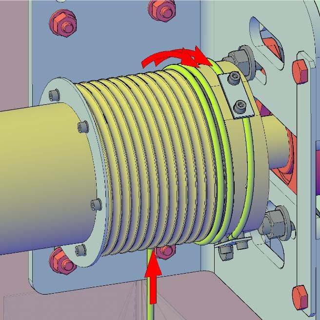
Wind the rope onto the drum, so that there are
at least two full turns (see pic. 47) when the
gate is in closed position. Pass the rope end as
shown in picture 48 below all three clamping
plates on the outer edge of the drum. Align the
two ropes so that they are equally tightened
on both sides. If the rope length is different,
there is a risk of jamming of the sections and
consequent damage of the wheels. Tighten the
clamping plate screws by torque max. 5 Nm.
After installing the ropes, remove the plastic
blade covers from the safety brakes and re-
move the screws that held the safety brakes in
the open position.
Picture 46
Picture 47 Picture 48
Somati system s.r.o., Jihlavská 510/2c, 664 41 Troubsko
IČ: 29260159, DIČ: CZ29260159
tel: +420 547 427 011, www.somati-system.cz
3114. COMPLETION OF THE INSTALLATION
14.1 Final adjustment
Perform at least 10 full open and close cycles to check smooth running of the gate. Make
record about the installation into the handover documentation.
14.2 Warranty information
According to the regulation No. 305/2011 of the European parliament and of the council,
Article 13 for warranty information, please, contact local importer in your country. Local
warranty conditions can be updated according to the local law regulations.
Somati system s.r.o., Jihlavská 510/2c, 664 41 Troubsko
IČ: 29260159, DIČ: CZ29260159
tel: +420 547 427 011, www.somati-system.cz
32You can also read