Nouveaux designs pour les ailes d'avion du futur bioinspirées
←
→
Page content transcription
If your browser does not render page correctly, please read the page content below
Académie de l'Air et de l'Espace

 Nouveaux designs pour les ailes d’avion du futur
 bioinspirées

 Marianna Braza IMFT* Coordonnatrice du projet EU- H2020 SMS**

 Collaboration: Jean-François Rouchon LAPLACE***, Directeur de
 l’ENSEEIHT

 ** Smart Morphing & Sensing for aeronautical configurations
 www.smartwing.org/SMS/EU
 *Institut de Mécanique des Fluides de Toulouse
 ***Laboratoire Plasma et Conversion d’Energie
 Unités Mixtes de Recherche : CNRS INPT UT3

 30/03/2021
De l’avion de Clément Ader, 1890
Vers de nouveaux designs des
ailes du futur

Voir film dédié par le CNRS à
nostre thématique:
https://lejournal.cnrs.fr/videos/the-
wings-of-the-future

 2
Augmentation des
 performances
 aérodynamiques:

 • Augmentation de la
 portance
(Beginner’s Guide to Aviation Efficiency, ATAG)
 • Réduction de la traînée
 • Réduction du bruit
4
Contexte de la thématique
 depuis 2010
 RTRA
6 post-doc, 4 PhD theses DGA, ANR, ENS Rennes, 1 post-doc MIT

2009-2016: STAE-RTRA1 research projects EMMAV and DYNAMORPH
 Platform www.smartwing.org 2
2014-2017: AIRBUS ETCT2
2017-2020: H2020 European Research Project SMS:
 Smart Morphing and Sensing
 for aeronautical configurations
 www.smartwing.org/SMS/EU 3

1Science et Technologies pour l’Aéronautique et de l’Espace – Réseau Thématique de
Recherche Avancée
 3 H2020 EU Project 2017 - 2020 endorser : Airbus Emerging Technologies and

Concepts Toulouse : ETCT
 5
Problématique:
Comment on peut implémenter différents
actionnements à plusieurs échelles de longueur et de
temps sur une aile d’avion

 Reduced Scale (RS) prototype: chord of 70 cm, span: 70 cm
 - Adaptation of embedded solutions with electroactive actuators in wind tunnel

 Large Scale laboratory prototype: chord of 2,4 m, span : 4m
 - Preuve de portage des concepts du morphing en échelle réelle

6
Dynamique tourbillonaire autour d’une aile d’avion: Problématique: Global scale : large amplitudes Comment on peut at low frequencies implementer différents Lift, Drag, Von Karman vortices actionnements à Smaller scale - shear layers… : plusieurs échelles de small amplitudes at higher frequencies longueur et de temps sur une aile d’avion Drag, Noise, Kelvin Helmhotz vortices 7
Airflow around an airfoil Different electroactive materials Global scale : large amplitudes Shape Memory Alloys at low frequencies Thermo-mechanical behavioural Lift, Drag, Von Karman vortices Smaller scale - shear layers… : Piezoelectric composite patches smaller amplitudes at higher Electro-mechanical behaviour frequencies Drag, Noise, Kelvin Helmhotz vortices Shape memory alloys G. Jodin et al, J. Fluids & 8 Structures 2017
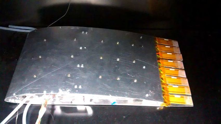
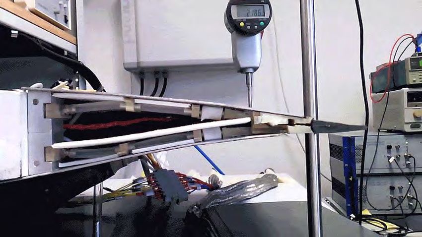
Prototype électroactif d’une aile Airbus A320 en echelle réduite (corde de 70cm) PhD G. Jodin Realization: large amplitude – low frequency Actuated length 200mm Tip displacement over than +/- 20mm (+/-10% of actuated length) 9
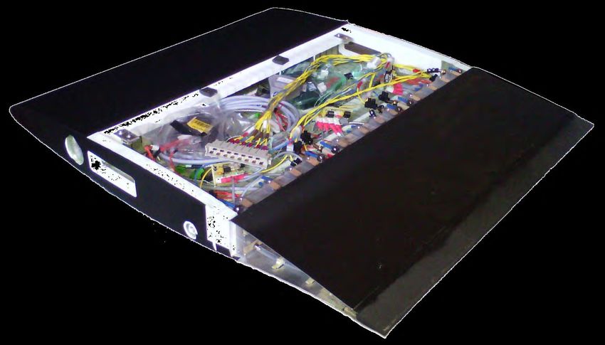
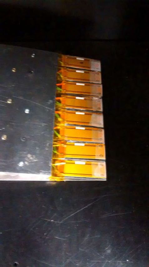
ACTIVATION A PLUS HAUTE FREQUENCE et à DE FAIBLES AMPLITUDES -
 Piezoactuators MFC et HYBRIDIZATION : SMA - MFC

 piezoelectric fiber composites (pfc)
 macro fiber composite (mfc)

PhD Thesis Johannes Scheller. The Royal Society annual exhibition 31 June-6 July 2014
ACTIVATION A PLUS HAUTE FREQUENCE DU BORD DE FUITE – A320
 “Higher Frequency Vibrating Trailing Edge (HFVTE) “

 35mm

11
Mechatronics Pressure sensors for turbulence control Thermocouples Strain gauges for Macro fiber close loop control composites Shape memory alloys 12
Comment on peut manipuler la turbulence
 pour créer un système interactif fluide-
 structure electroactive pour accroître les
 performances aérodynamiques.

 I. Régimes subsoniques correspondant aux phases de vol
 du décollage et d’atterrissage

13
Vortex shedding in the wake of an airfoil Detachment Creation and mixing after the trailing edge VK KH Free stream Trailing edge shape control Energy introduction in shear layers 14
Experimental set up Subsonic wind tunnel S4 IMFT Uinf < 35m/s Wing chord C=0.7m Rec=500k and 1M Reynolds number relative to the chord Aerodynamic balance Embedded pressure sensors HS TR PIV measures(1) High Speed Time Resolved Particle Image Velocimetry From 6000 to 9500 fps Software DAVIS7 and CPIV(2) 15 (1)S. Cazin, M. Marchal (2)CPIV by P. Elyakime IMFT
Turbulent-Non-Turbulent
 Interface (TNT)

 Turbulent-Turbulent
 Simiriotis et al, J. Fluids & Structures 2019
 Interface (TT)

 Optimal manipulation of the TNT and TT Interfaces
 Feedback towards the structure

16 G. Jodin - N. Simiriotis
Morphing effects on airflow Instantaneous fields Vortex breakdown Trailing edge vibrations chop wake vortices Eddy blocking effect Energy introduction causes wake thinning Static (no morphing) Morphing HFVTE Fa=220Hz A=0.6mm G. Jodin, V. Motta, J. Scheller, E. Duhayon, C. Döll, J.F. Rouchon, M. Braza. ``Dynamics of a hybrid morphing wing with active open loop vibrating trailing edge by Time-Resolved PIV and force measures'', Journal of Fluid and Structures, 2017 17
PIEZO-ACTUATION:
Breakdown of the trailing edge vortices and loss of coherence.
Decrease of the amplitudes regarding the corresponding
predominent frequencies

 Trailing- Actuation Attenuation
 edge
 instability of the
 mode trailing-
 edge
 shear-layer
 instability

 Vortex
 breakdown
HFVTE effect (Higher Frequency Vibrating Trailing Edge, low amplitude ~0.1%Chord) HFVTE adds 2% more lift Voltage (%) Lift Lift improvement limited by actuation amplitude is measured constant (measure accuracy) 19 Worst case is +0.4% at +2%
Analyse physique des effets du morphing à l’aide de
 simulation numérique et comparaison expérmentale
 • Low amplitude – Higher frequency trailing edge vibration with
 piezoelectric actuation.
 • Polynomial deformation (ALE for deformable grid) of the trailing edge to
 mimic experiments. Multiple frequencies tested for 2D case .

 Figure: Higher frequency Figure: Polynomial deformation
 trailing edge vibration on the of trailing edge.
 small scale prototype

25
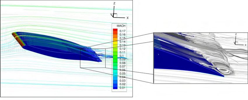
Structure de l’écoulement 3D: RS Reduced scale A320 wing- SMS
 Reynolds = 1M (based on chord), Ma = 0,06 at inlet, AoA 10 degrees.

 Iso-rotationnel wz coloré par la
 composante du rotationnel
 longitudinale, wx
 Simulations Hi-Fi par le code
 NSMB - Navier Stokes Multi-Block
 Modélisation Turbulence avancée

 Lignes de courant illustrant la
 région de recirculation

 PhD A.Marouf : Collaboration IMFT - LAPLACE -
 ICUBE Univ. Strasbourg
22

 Effects on the Aerodynamic Forces

 Fig: Variation of lift (top) and drag (bottom)
 coefficients with the actuation temperature.
 Zero frequency corresponds to no-actuation
 (Static).

 Table: Effect of vibrating actuation on the
 averaged aerodynamic performance.
 CL CD CL/CD
 Static 1.5646 0.0219 71.5
 60 Hz 1.5894 0.0214 74.4 (4.1%)
 300 Hz 1.6147 0.0217 74.5 (4.2%)

 26 PhD N. Simiriotis
23

 Effect on Wake Dynamics

 alternating sheading ≈
 210Hz

 low shear layer >
 300Hz

 No Morphing Applied (Static) = – amplitude 0.35mm = – amplitude 0.35mm

 • Effect of vibrations on flow field ; lock-in leading to reinforcement of the lower shear layer leading
 to suppression of the von Kármán alternating vortex shedding.

 27 Simiriotis et al, J. Fluids & Structures 2019
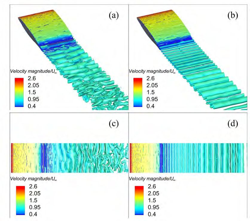
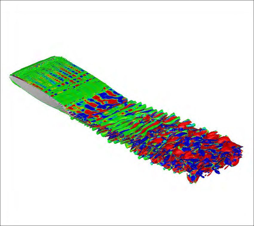
Suppression de la tridimensionnalité par vibrations optimales Optimal morphing frequency 300Hz, 0.70mm of deformation Suppression of three- dimensional character of the wake Formation of two-dimensional rows PhD A. Marouf, October 2020
REDUCTION de la largeur du sillage et des sources du bruit Légère inclinaison du sillage vers le bas Diminution du deficit de la vitesse (diminution du cisaillement) Réduction de la largeur du sillage Réduction des sources du bruit aérodynamique
DYNAMIC CAMBER EFFECTS ON THE RS Prototype
of the SMS project:
TIME-RESOLVED Particle - Image Velocimetry TRPIV
S4 Wind Tunnel IMFT.
PhD M. Carvalho ‘21. Collaboration S. Cazin, M. Marchal
27
 Hybrid morphing effect
 HFVTE adds
 2% more lift
 (%)

 +Noise sources reduction

27
 G. Jodin - M. Carvalho
The Large-Scale LS Prototype of the SMS project:
 Aile de type A320 + volet hypersustentateur en morphing

 hybrid electroactive morphing
 at full scale

Towards integration at scale 1: large scale prototype including synergy of wind tunnel
experiments and simulations

28
Specifications Adaptive morphing flap No impact on high lift function Based on A320 geometry 1m chord, 2m span Camber control under realistic loads Aerodynamic forces about 1.5tons Trailing edge displacement +/- 10%C Shape tolerance
CAMBER EFFECTS ON THE MORPHING HIGH - LIFT FLAP
EMBEDDED IN WING - FLAP CONFIGURATION IN TAKE-OFF
Articulated concept
 5 articulations.
Total Chord 1m
Actuated chord 0,85 m
 cf. Reference profil
Non-actuated from "LS (cambered
geometry shapes) tab
Span length 0,5m
Elastic skin thickness 1,5mm
Deformation
amplitude 0,1m
Actuation time
constant 60s

 100
 Reference profile
 Shape Up
 0
 0 100 200 300 400 500 600 700 800 900 1000 1100 Shape Down

 -100
MORPHING FLAP FINAL DESIGN CAD

 • Skin

• Actuators

 • Ribs

 • Longeron • Stringers

 32
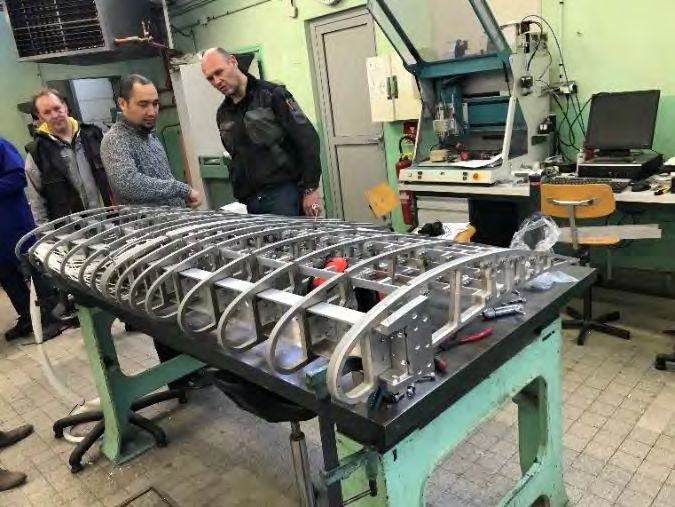
MORPHING FLAP MANUFACTURING AT IMFT WORKSHOP

Collaboration : IMFT - LAPLACE

 33
MORPHING FLAP STRUCTURE : INTEGRATION VERIFICATIONS AND SIMULATION

 Green curve : Baseline (0cm TE deflection)
 Violet curve: Camber 1 (3.3 cm TE deflection)
 Brown curve :Camber 1 (6.6 cm TE deflection)
 Blue-green curve:Camber 1 (10 cm TE
 deflection)

 IMFT S1 wind tunnel

 Full scale subsonic
 Morphing prototype of A320 type: flap’s chord of 1m

 The SMS LS Prototype Experimental set-up 34
LS Prototype – design par les simulations
 de Haute Fidélité
 Take-off configuration C=2.40 m, C(flap)=1m

 2
LARGE SCALE A320 Morphing Prototype with high-lift flap
 Take-off Configuration

 α=8.2°
 Re = 2.25M

Streaklines in the wake and the pressure field in the wing-flap : Simulations by the NSMB Code:
Navier-Stokes MultiBlock of the EU Consortium
Coherent structures dynamics Optimal trailing-edge actuations : 300 Hz Streaklines visualization on the median section Smaller scale organized structures injected in the shear-layer Thinner wake developed Time-Resolved PIV Experiments PhD A. Marouf : IMFT-ICUBE - LAPLACE 37 Simulations
Influence de la fréquence des vibrations
 STATIC 30 Hz 60 Hz

 100 Hz 200 Hz 300 Hz

 38
Static configuration versus morphing

 fSL fSL
 fSL

 fact

 Static Morphing

Amincissement du sillage démontré par analyse modale POD
Suppression de la tridimensionnalité et des dislocations des allées
tourbillonnaires - source d’augmentation du rms des forces aérodynamiques
Maillage de 50 : PRACE - EU Supercomputing Allocation Tier0
Voir article dédié: https://prace-ri.eu/future-aircraft-wings-will-be-able-
to-adapt-their-shape-mid-flight/.

 PhD A. Marouf
Aerodynamic performances

 By the only effect of vibrations 41
Effets de cambrure LS prototype - Simulations
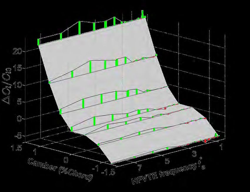
Aerodynamic performance by the cambering
 effect/optimal deformed shape

 Re = 7 million

 Position 1 Position 2 Position 3 Position 4

 0° + 13.76 + 20.67 + 22.67 + 22.74
 / − /
 X 100 2° + 7.97 + 10.35 + 10.79 + 10.41
 /
 4° + 3.26 + 2.63 +1.21 +0.21

 43
Angle of 4° (morphing) compared to 8° (reference)
• For a lower angle of incidence in the Take-off than the conventional:
 Higher aerodynamic performance obtained

10%
II. Morphing - phase de vol de croisière
Morphing par vibrations optimales et légères déformations de la région proche du
 bord de fuite: A320 type wing
 Increase of the aerodynamic performance in cruise by modifying the shock
 boundary layer interaction

CL

 Instabilité du tremblement et Mach=0.78, Re=2.93 x 10⁶ M, angles of incidence from
 interaction avec la turbulence 1.8 to 5°
 et tourbillons cohérents du
 sillage proche: von Kármán et
 Kelvin-Helmholtz

 PhD J.B. Tô
A=1.18, M=0.78 A320 Le tremblement du régime
 transsonique autour d’une aile
 supercritique
Exps TFAST EU Project

The feedback interaction advances
(green) event upstream and below the
shock foot : separated region creating
local thickening of the boundary layer
and 48
 secondary shock formation

 J.B. Tô et al, J. Fluids & Structures 2019
Morphing bord de fuite: Actionneurs: effet de rétroaction entre le bord de fuite et l’écoulement amont:
 Suppression de l’instabilité
 du tremblement -
 angle de déflection optimale

 Vitesse amont correspondant à la phase
 de vol de croisière réelle
Augmentation de la finesse aérodynamique:
rapport : portance/résistance au vent
ANALYSE DU COMPORTEMENT OPTIMAL - DYNAMIQUE DU SILLAGE ET EFFET DE
RETROACTION (FEEDBACK) SUR LA REGION DU CHOC ET EN AMONT DE CELLE-CI

 STATIC 200 Hz

 350 Hz
Effets du morphing - avion complet de type A320

 • Projet SMS : Simulations PhD A. Marouf en collaboration : CFS -
 Engineering Lausanne - partenaire du projet SMS avec ICUBE - IMFT -
 LAPLACE
Conclusion: Electroactive hybrid morphing through turbulence manipulation:
 a multidisciplinary approach

 Bio-inspiration Reduced Scale prototype
 SMA – piezo: hybrid morphing
 Models – design
 Mechatronic system

 Camber
 Feather
 vibrations
 Experimental investigation
 in wind tunnel

 Approches couplées: Prototypage
 (actionneurs intelligents),
 Airflow physical analysis Expérimentale et numérique
 Turbulence manipulation
 fluid-structure-interaction Large Scale A320
 wing/high-lift flap
 Morphing impact in take-off on Towards full scale
 the RS prototype (70 cm chord): Innovative technologies
 Camber +3.5% more CL/CD Optimized design
 Flapping: +2% more Lift Electroactive camber control
 In cruise: +5.5% CL/CD
52
Conclusion Cambering with optimal shape : Increase of 7% lift in Take-off after the experiments Polytech Milano Trailing-edge vibration in cruise: Decrease of drag by 4% - experiments of IMP-PAN - Gdansk and - 9% by simulations The hybrid morphing using optimal trailing-edge actuations and cambering results for the high-lift configuration results in : Drag decrease up to -0.78% using hybrid morphing compared to the only cambering control . Increase of CL/CD of +0.50% more with hybrid morphing than only cambered flaps
Current studies and outlook Morphing thanks to “live-skin” design on strategic parts of the wing Thanks to novel generation of actuators under study Multiple degrees of Freedom for deformations & vibrations Controller through Artificial Intelligence Intelligent manipulation of the TNT “Turbulent- Non-Turbulent and “Turbulent-Turbulent” Interfaces Enforced increase of the aerodynamic performances beyond current limits
Merci de votre attention

 Marianna Braza - groupe ASI - IMFT
 J.F. Rouchon - groupe GREM3 - LAPLACE
 et tous les collègues et étudiants participant
 à la thématique pluridisciplinaire du morphing électroactif
 bio-inspiré

55
56
You can also read