A STUDY OF HIGH LIFT AERODYNAMIC DEVICES ON COMMERCIAL AIRCRAFTS
←
→
Page content transcription
If your browser does not render page correctly, please read the page content below
AVIATION
                                                                                                                                  ISSN: 1648-7788 / eISSN: 1822-4180
                                                                                                                          Article in 2020 Volume 24 Issue 3: 123–136
                                                                                                                         https://doi.org/10.3846/aviation.2020.12815

                             A STUDY OF HIGH LIFT AERODYNAMIC DEVICES ON
                                        COMMERCIAL AIRCRAFTS

   Swamy Naidu Venkata NEIGAPULA                                1,   Satya Prasad MADDULA                      2,   Vasishta Bhargava NUKALA                       3,*

                           1Department
                                 of Mechanical Engineering, National Institute of Technology, Raipur, India
                                  2Department
                                      of Aerospace Engineering, GITAM University, Hyderabad, India
         3Department of Mechanical Engineering, Sreyas Institute of Engineering and Technology, Nagole, Hyderabad, India

                                                      Received 08 March 2019; accepted 18 May 2020

       Abstract. Aerodynamic performance of aircraft wings vary with flight path conditions and depend on efficiency of high
       lift systems. In this work, a study on high lift devices and mechanisms that aim to increase maximum lift coefficient and
       reduce drag on commercial aircraft wings is discussed. Typically, such extensions are provided to main airfoil along span
       wise direction of wing and can increase lift coefficient by more than 100% during operation. Increasing the no of trailing
       edge flaps in chord wise direction could result in 100% increment in lift coefficient at a given angle of attack but leading
       edge slats improve lift by delaying the flow separation near stall angle of attack. Different combinations of trailing edge flaps
       used by Airbus, Boeing and McDonnel Douglas manufacturers are explained along with kinematic mechanisms to deploy
       them. The surface pressure distribution for 30P30N airfoil is evaluated using 2D vortex panel method and effects of chord
       wise boundary layer flow transitions on aerodynamic lift generation is discussed. The results showed better agreements
       with experiment data for high Reynolds number (9 million) flow conditions near stall angle of attack.
       Keywords: flap, slat, aircraft wing, high lift, aerofoil, drag, pressure.

Introduction
                                                                                        and moment coefficients. The use of multi-element air-
Slats and flaps are high lift devices, intended to produce                              foils, for example 30P30N as found on commercial aircraft
maximum lift coefficients on aerodynamically designed                                   wings has been a good subject of case study by several
surfaces as found on aircraft wings, helicopter blades. The                             researchers in the past for analyzing aerodynamic per-
use of aerodynamic extensions are done in order to in-                                  formance under different flow configurations (Reckzeh,
crease the effective plan form area of wing thereby gener-                              2004; Sankar et al., 2001; Catalano et al., 2012; Lockhard &
ating extra lift force required for an aircraft wing. An air-                           Choudhari, 2009). The research methods included various
craft wing is subjected to varying flow conditions during                               tests in wind tunnel experiments, for instance the effect on
take-off or landing as well as cruise modes. Typically, the                             aerodynamic performance of aircraft wing by varying the
flow field surrounding many of the aircraft wing structures                             wall or ground distance to the wing surface (Xuguo et al.,
is highly non-linear and unsteady in nature. The unsteady                               2009; Lockhard & Choudhari, 2010). In addition to aero-
flow nature on wing can be analyzed by computational                                    dynamic performance, aero-acoustic studies have been
methods accurately (Reckzeh, 2004; Sankar et al., 2001;                                 done by several researchers in the past decade (Pascioni
Catalano et al., 2012). It is known that CFD based methods                              et al., 2014; Lockhard & Choudhari, 2010; Jawahar et al.,
such as URANS, large eddy simulation, direct numerical                                  2017). Studies revealed that flow induced noise from slats
simulation produce highly accurate results but are compu-                               and flaps could be reduced through boundary layer con-
tationally intensive for predicting flows at high Reynolds                              trol and involve blowing and suction procedures. These
number and for complex geometries. In contrast, other                                   methods control the boundary layer thickness while re-
computational methods such as basic panel methods by                                    ducing pressure drag on inboard and outboard sections of
Hess and Smith (1967) are suitable to analyze potential                                 wing. Even though most high lift devices such as trailing
and incompressible flows over multi element airfoils. The                               edge flaps are intended to increase the maximum lift coef-
aerodynamic performance of an airfoil includes lift, drag                               ficient for a modern aircraft they also introduce additional

*Corresponding author. E-mail: vasishtab@gmail.com

Copyright © 2020 The Author(s). Published by Vilnius Tech Press
This is an Open Access article distributed under the terms of the Creative Commons Attribution License (https://creativecommons.org/licenses/by/4.0/), which permits unre-
stricted use, distribution, and reproduction in any medium, provided the original author and source are credited.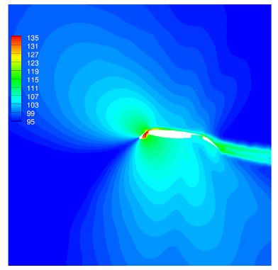
124                                    S. N. V. Neigapula et al. A study of high lift aerodynamic devices on commercial aircrafts

drag known as interference drag and tend to offset the            lift improvement methodologies through use of slots on
benefits. So, fairings are used to streamline the flow and        leading and trailing edge regions of airfoil. The techniques
can minimize the form or interference drag. Trailing              available to improve lift coefficient are described and the
edge flaps are mounted on aircraft wing using kinematic           importance of such devices in aircraft wings as well as the
mechanisms that can be deployed during landing, takeoff           benefits pertaining to aircraft industry. In second section,
conditions. The role of kinematic mechanisms is dealt in          maximum lift coefficients achieved for different types of
section 2.2 which explains the functioning of mechanisms          high lift configurations on commercial aircraft wings are
common to commercial aircrafts. The leading edge and              discussed as well as role of the kinematic mechanisms. In
trailing edge flaps on high lift systems are mounted using        third section, steady state surface pressure coefficient has
fairings (Zaccai et al., 2016).                                   been evaluated for 30P-30N multi-element airfoil using
     Heap and Crowther (2011) studied the various con-            2D vortex panel method and validated with CFD results
figurations of such high lift devices on aircraft wings that      of Dong and Zhang (2012) and experiment results of An-
are available on commercial airliners such as Boeing, Air-        derson et al. (1995) at 16° angle of attack, Mach-0.2, Re-9
bus, McDonnell-Douglas (now Boeing). Tradeoff studies             million. Finally conclusions and an overview of the future
were conducted for various wing configurations by manu-           work is presented.
facturers in aviation industry and factors affecting flight
performance for commercial aircrafts are studied. In a            1. Significance of high lift devices
study by Husse (2006) several conditions were considered
to investigate the fuel consumption by aircrafts during its       High lift devices are sophisticated equipment found on
operation, lift–off and landing scenarios. Furthermore,           commercial aircrafts that are not only designed to produce
computational study by Xuguo et al. (2009), Deng et al.           increased lift but also to improve the flight performance. A
(2018) has shown the effects of ground height distance to         typical passenger aircraft has three stages in a flight, take-
airfoil on the lift, drag and nose up or nose down pitching       off, cruise and landing during which the high lift devices
moments of an aircraft for two different airfoil configura-       are deployed and retracted when required. Their position
tions. Firstly by varying the ground distance height for          can be located either at leading edge as well as trailing
clean airfoil under different flow condition using the lift       edge of an aircraft’s main wing. From Figure 1(a) a plain
drag and moment coefficients. Secondly for a high lift con-       or slotted flap is flexible element attached to lower sur-
figuration, a multi element airfoil, 30P30N was considered        face of trailing edge and deployed at 20°. A split flap or a
for similar distance to ground height case. It was found          spoiler is located aft of main wing and intended to act as
that for high lift configurations, lift, drag and nose down       aerodynamic brake by stalling the flow and creating high
pitching moments have decreased. However, in the former           pressure drag. A zap flap is similar to a split flap but oper-
case, lift and nose down pitching moment increased up to          ates using a hinge and fairing in kinematic mechanism at
a certain value, while induced drag was found to decrease.        the cove region. The most frequently used leading edge
The investigated parameter was measured in terms of ratio         flap in aircraft is Kruger flap or a three-position slat that
of ground distance height and chord length of airfoil con-        forms a unique combination with main element. As it is
figuration and its effect on surface pressure distribution        operated by a complex kinematic mechanism, the deploy-
was also dealt for such conditions. The ground effect was         ment of such flaps can be done very precisely in order
combined with boundary layer flow transitions on airfoils         to increase the maximum lift coefficient during takeoff or
to analyze confluent boundary layer flow characteristics          landing. Increasing slots either at leading or trailing edge
between the flap gap and main element. The presence of            of wing will improve the maximum lift coefficient by an
vortices formation for confluent flows at varying angles          order of two or three times higher compared with clean
of attack also confirmed the airfoil experienced higher lift      configuration of wing. This allows the increase of payload
coefficient for different Reynolds numbers. Studies from          or takeoff weight of aircraft at a given angle of attack for
Zhang et al. (2017), Jain et al. (2015) have shown that           a flight Mach number. It would also help to control the
effect of Gurney flaps on NACA 0012 airfoil attached at           dynamic stability of aircraft during low altitude maneuver
~1.5% c distance from trailing edge increases maximum             such as during landing (Reckzeh, 2004) The position of
lift coefficient by 2% but at the expense of increased pro-       slots is critical to increase maximum lift coefficient. Fig-
file drag. The use of Gurney flaps was first investigated by      ure 1(b) shows the arrangement of high lift devices on the
Liebeck (1978) using inverse design approach to deter-            main wing during take-off and landing stages. Figure 1(c)
mine high lift on airfoils. The influence on the maximum          depicts the leading-edge profile of a real wing mounted
lift coefficient on the wing due to addition of Gurney flaps      with slat and uses a fairing for deployment. Figure 1(d) il-
known as tabs in the flap cove region has shown to in-            lustrates the trailing edge flap devices of a Boeing 747-400
crease in lift coefficient and nose down pitching moment          deployed during landing. Typically arrangement of high
coefficient for multi-element airfoil due to downward ac-         lift devices along span wise direction is near inboard as
tion of force along chord.                                        well as outboard regions of wing.
     This paper is confined to following sections of study. In         Figure 2 depicts the innovation cycle and state of art
first section, the primary significance and objective of high     in aircraft wing design. It can be noted that the evolution
lift devices on aircraft wings presents a discussion about        of wing design is dependent on the innovative materials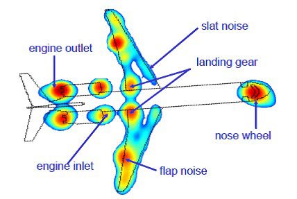
Aviation, 2020, 24(3): 123–126                                                                                                                 125

as well as kinematic mechanisms to enhance overall flight                          of aircraft is low and thus a high lift and low drag action is
performance. The generation of lift on an aircraft wing is                         produced. This helps to increase the pay load capacity or
caused as result of pressure gradient between suction and                          take-off weight of an aircraft. For smooth landing condi-
pressure surfaces of wing. The amount of lift produced                             tions the aircraft must again slow before the touch down
varies with geometry and structural parameters of airfoil                          on runway for which the trailing edge flap devices are de-
viz. leading-edge radius, trailing edge angle, camber, thick-                      ployed to produce high lift and high drag on wing surface
ness to chord ratio. The deployment of trailing edge flap                          as shown in Figure 1(b) (Husse, 2006) A leading edge slat
and slat is done for the takeoff stage partially as velocity                       combined with double slotted flap produces a CLmax of
                                                                                   ~4 by increasing the effective camber and wing area. The
                                                                                   increase in camber is best achieved by a slat near leading
                                                                                   edge as shown in Figure 1(c). This affects the maximum
                                                                                   CL during take-off or landing requirements of aircraft and
                                                                                   subsequently the fuel efficiency.
                                                                                       One of the major objectives of high lift devices in air-
                                                                                   craft design is to minimise drag at high speeds since drag
                                                                                   becomes critical factor when components are not stream-
                                                                                   lined which result in early flow separation on surfaces.
                           (a)                                    (b)              Therefore, the components are designed in streamlined
                                                                                   manner to which the air flow can remain attached all
                                                                                   the way back to a trailing edge of the wings. The design
                                                                                   process is similar for tail surfaces and a sharp closure at
                                                                                   the tail of the body contributes to dramatic increase in
                                                                                   parasitic drag at high speeds. Also, the air flowing over
                                                                                   the bluff bodies like cylinder would leave a wake full of
                                                                                   swirls and contribute to a large amount of pressure drag. A
                                                                                   higher pressure drag produced by the shape of the aircraft
                                                                                   is kept to a minimum by streamlining, ensuring the flow
                           (c)                                    (d)              to remain attached on surface. Streamlining reduces the
                                                                                   boundary layer thickness and pressure drag. However, the
  Figure 1. Position of high lift devices (a) Different types of                   aerodynamic improvement in the design of the wing itself
   flap and slat configurations on aircraft wing (IATA, 2019)
 (b) Position of flap and slap devices during aircraft operation
                                                                                   involves a balance among conflicting factors (Chernyshev
  modes (Haroon, 2011) (c) Ventilated and fixed leading edge                       et al., 2019).
     slat (d) Slotted flaps of Boeing 747-400 during landing

                                                                                    Delta wing          Flexible elastomeric wing

                                 Transition
                                                            Hyper path

                                                                                                                              (2010 –Future)
     Trend in Innovation

                                                                                                      Morphed wing

                                                                         Winglet /Raked tip      Split Fenced tip

                                              Feedback of ideas                                                             (1980 – 2010)

                                    Incremental                                                                 Swept tip
                                   Improvements

                                                                                  Biplane wing    (1930)

                                                                                                                              Time

              Figure 2. A roadmap of innovation cycle compared to evolution of aircraft wing innovations (adapted from Husse, 2006)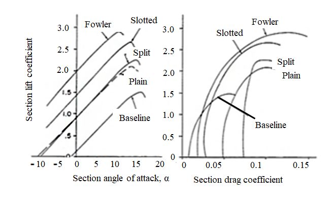
126 S. N. V. Neigapula et al. A study of high lift aerodynamic devices on commercial aircrafts
The aspect ratio and thickness to chord ratio of aero- tion and prevents dynamic stall over main airfoil (Heap
foil are important design variables in aircraft wing design. & Crowther, 2011). Figure 3(b) shows the sectional lift
When the wing span is increased it reduces friction drag coefficient comparison for plain and slotted wings. The
but increases the weight of wing. Increasing wing thick- maximum CL of 3.2 is obtained for wing using a fowler
ness reduces structural weight because thinner skins can flap with ~65% improvement. In Figure 3(c) the effect of
be used, but increases drag, especially at the high speeds no of slots on improvement of lift coefficient is illustrated.
of cruising flight. On the other hand, low aspect ratio in- The takeoff and landing performance of aircraft vary with
creases wing area and makes it possible to take-off and acceleration distance on ground as well as stepped climb
land at lower speeds and requires shorter runways how- rates with a slope angles between 2° and 3°. The thrust to
ever it usually results in increase of skin-friction drag at weight ratio, span wise wing loading, maximum lift coef-
high speeds for the rest of the flight. ficient, pressure and friction drag are other factors which
Improvements in aerofoil design are focused particu- affect the take-off attitude of aircraft (Reckzeh, 2008; Heap
larly at the high-speed phase of flight. Such improvements & Crowther, 2011). In contrast the landing performance
have made it possible to find more favourable balance be- also depends on additional parameter known as the ap-
tween span, thickness, area, and weight. The tip of a wing proach angle and distance to approach. The takeoff and
is critical in design of an aircraft. Adding winglets tilted landing of civil aircrafts is done according to federal air-
upward at the tips, either to new aircraft or as retrofits to worthiness regulations (FAR) part 25 (FAA, 2019). Civil
existing models, has seen 3–5% reductions in fuel burn, aircrafts use actively controlled leading slats or Krueger
depending on the length of the flight and type of aircraft. flaps which can be deployed in different positions during
Winglets also reduce induced drag without needing a sig- takeoff and landing situations in order to reduce structural
nificant increase in horizontal span. Although winglets are load on wing. Empirical studies have found that pay load
beneficial during long range flight operations, the pres- capacity increase roughly an order of 1–2% with a change
ence of winglets would be an issue for parking at some of 3% in maximum CL or glide ratio of a wing. The gross
airport gates, for increase in wingspan. An alternative to tonnage in Boeing series of aircraft allows 560–600 tons
the winglet is the raked tip as which produces similar drag with a total payload up to 60 tons. According to study of
reduction for long-range aircraft, providing a lightweight Reckzeh (2004) for a twin engine jet aircraft a 5% increase
wingtip design. in CLmax leads to 12–15% increase in payload, while a 5%
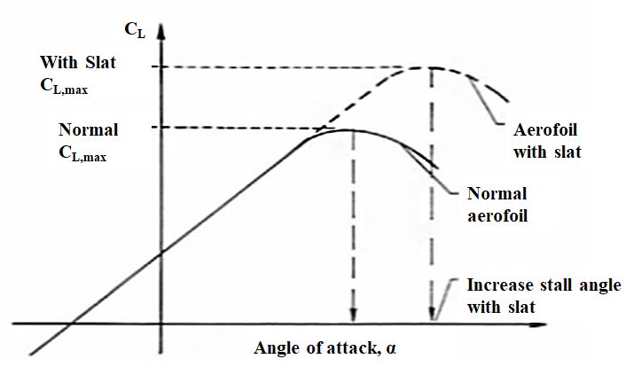
From Figure 3(a) slat contribution to lift augmenta- increase in L/D ratio increases payload by 20%. Similarly
tion at a given angle of attack is significant and increases a 5% increase in CLmax during landing would increase
the maximum CL or L/D ratio by 80–100%. Presence of 25% of payload. The design process of such wings involve
leading edge slat delays the boundary layer flow separa- advanced tools such as CFD flow solvers to resolve the
(a) (b)
Figure 3. Illustration of the maximum lift coefficient vs
angle of attack (a) airfoils with and without leading edge
slat (IATA, 2019) (b) drag polar for various types of flaps
with respect to baseline airfoil (IATA, 2019) (c) varying
number of slots on aircraft wing (Rudolph,1996)
(c)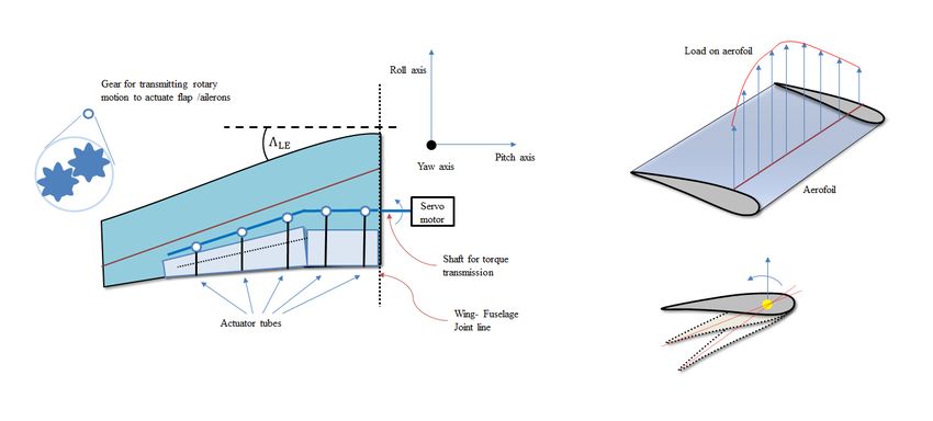
Aviation, 2020, 24(3): 123–126                                                                                                  127

 complex boundary layer flow physics. For high lift sys-                          flaps at trailing edge for inboard and outboard sections
 tems, the takeoff and landing performances are dependent                         of wing. The inboard section of wing double slotted flaps
 upon the acceleration distance on ground, climb rates,                           are used while for outboard station single slotted flap is
 approach angle and deceleration distance on ground. In                           utilized to produce maximum lift as found in Boeing B767
 case of takeoff performance, the aircraft climb rate can be                      and B777. The double slotted trailing edge flaps are used
 found using Eq. (1)                                                              in Douglas aircrafts, DC8-63/77, MD-11.
           T      1                                                                   The slotted configuration contains the curvature of
      =
      φ       −        ,                                    (1)                   aft filler region near trailing edge which affects the maxi-
          W L/D
                                                                                  mum lift distribution and load carrying ability of wing.
 where, T is the total thrust force, W is the total weight of
                                                                                  The presence of high lift elements will improve flight per-
 aircraft, L – total lift produced by wing, D – total drag on
                                                                                  formance by increasing effective camber and wing area.
 aircraft. The acceleration distance on ground is expressed
                                                                                  It controls the surface pressure peaks and varies the lift
 by Eq. (2)
                                                                                  force on wing but also introduces induced drag. It is un-
              W L                                                                 like the viscous and wave drag produced due to boundary
=     sa f ( , , CL max , CD , µ) .                         (2)
               S D                                                                layer thickness, fluid viscosity and shock waves formed on
     On the other hand, for the landing performance of an                         wing at supersonic and transonic flight speeds. One of the
 aircraft, the approach angle is limited to 3° according to                       important objectives to add slots on aircraft wing is to en-
 FAR rules. It is expressed in terms of wing loading and                          hance maximum lift coefficient. Lift coefficient has direct
 glide ratio and given by Eq. (3)                                                 impact on takeoff weight of aircraft and fuel consumption
             W L                                                                  efficiency during take-off and landing.
      ϕ = f ( , , CL max ) .                                (3)                       However, it has been found that during cruise stage,
              S D
     The deceleration distance on ground for an aircraft is                       control of boundary layer thickness is important strategy
 given by Eq. (4)                                                                 to reduce the pressure drag which leads to the reduction
                                                                                  in fuel consumption by average of 5% during such flight
              W                                                                   conditions (Heap & Crowther, 2011). The capacity of the
=     sd f ( , CL max , CD , µ,TR) .                        (4)
               S                                                                  fuel tank is based on the position of such devices along
     The climb rate for landing is also function of thrust to                     the wingspan and volume of fuel consumed as function of
 weight ratio and glide ratio and given by Eq. (5)                                thrust to weight, lift to drag ratios. As with global change
              T L                                                                 in price of aviation turbine fuel seen over the last decade
      φ=f( , ),                                             (5)
             W D                                                                  (IATA, 2019) any improvement in fuel consumptions of
 where, S – wing span area, CLmax is maximum lift coef-                           aircraft will provide huge benefits to aviation industry as
 ficient, µ is the friction coefficient during ground roll, TR                    well as reduction in harmful carbon emissions. It is es-
 is the reverse thrust force. It can be noted that no of trail-                   timated that each ton of fuel saved leads to reduction of
 ing edge slots to generate maximum lift vary with aircraft                       ~3–4 tons in CO2 emissions (Husse, 2006). Also, following
 manufacturer and flight range. The total drag for an air-                        the perfect flight procedures reduce flight time. A 10 min
 craft wing is evaluated by Eq. (6)                                               reduction in time can save up to 4500 liters of fuel which
                                                                                  translates to elimination of 13000 kg of carbon emissions.
                                                                          CL2     The fuel consumption for an aircraft is influenced by the
           C=
            D CD 0 + ∆CD , flap + ∆CD , slat + ∆CD , gear + ∆CD ,wave +       ,
                                                                          πAe     structural weight and the lift produced during take-off and
                                                                     (6)          landing stages. During takeoff, the angle of climb (AOC),
           e is Oswald efficiency factor expressed in terms of flight             rate of climb (ROC) are critical parameters that affect the
           Mach number, wing aspect ratio, span wise airfoil thick-               fuel consumption. According to federal aviation adminis-
           ness, wing sweep angle and number of engines on wing.                  tration (FAA) regulations part 25 if the angle of climb or
           Typical values for e depend on the position of flaps, slats            rate of climb is increased, the fuel consumption by an air-
           and landing gear. The value of this factor is high when the            craft will also increase. The lift produced on aircraft wing
           high lift elements are in retracted state than when they               will also vary with angle of incidence, position of flap and
           are extended or deployed. CDo is the zero lift drag when               slat devices. Similarly, during descent stage, a shorter land-
           the high lift devices are in retracted position. ∆CD , flap ,          ing distance will tend to increase fuel consumption and
            ∆CD , slat , and ∆CD , gear are additional drag contributing          vice-versa.
           elements. ∆CD , wave is drag increment due to flight Mach                  The aerodynamic efficiency of a high-lift system varies
           number. CL is the lift coefficient, A – aspect ratio of wing.          with number of flap or slat elements along with the sup-
                                                                                  port and actuation system. Essentially flap support systems
           2. Configuration of high lift devices on                               can be divided into (i) fixed or simple hinge, (ii) track
           commercial aircrafts                                                   system (iii) linkage system. Fixed hinge system consists of
                                                                                  simple flaps and allows only rotational motion about pivot
           Various combinations of lift enhancing devices on inboard              point. Track and linkage systems consist of combination
           and outboard sections of aircraft wing at the trailing edge            of flaps attached to fairing and involve a rotational mo-
           are shown in Figure 4. It also shows the double slotted                tion about a pivot point and also forward traverse such as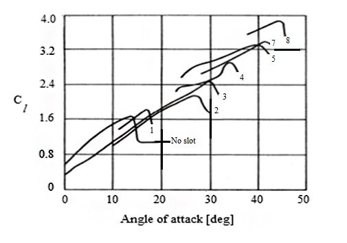
128                                             S. N. V. Neigapula et al. A study of high lift aerodynamic devices on commercial aircrafts

                                                                                 Position on wing span

                                                              Inboard                             Outboard

                                  B-727, B-737, B-747

                                  A-321, A-300, B-757
                 Aircraft model

                                     B-767, B-777

                                  DC 8-63/70, MD -11

                                        Legend: A – Airbus, B – Boeing, DC – Douglas Craft, MD – McDonnel Douglas

      Figure 4. Schematic view of trailing edge flap/slat configurations used in Boeing, Airbus and McDonnel Douglas aircrafts
                                        (adapted from Heap & Crowther, 2011; Reckzeh, 2004)

Fowler motion. In order to reduce cruise drag the drooped                   ations. The inboard wing of aircraft is usually equipped
hinge has to be moved further up resulting in a smaller                     with a droop nose device during a takeoff or landing
flap fairing. Kruger flaps are used on several passenger                    operation, since it offers good aerodynamic performance
transport aircrafts due to light weight structure and sim-                  compared to sealed leading-edge slat. Figure 5(b) shows
ple design. However, Kruger flaps usually have only two                     the variable camber Krueger leading-edge flap device. A
operating modes viz. cruise and extended and as a result,                   simple Kruger flap with fixed camber is in shape of bull
take-off performance may be less efficient compared to                      nose and designed to improve the landing performance.
three-position slats. An advantage of Kruger flaps over                     Also, a variable camber Kruger flap is equipped with a
slats is that only the pressure surface of the cruise air foil              rotary track linkage in order to increase the maximum lift
is affected at the leading edge and thus resulting surface                  coefficient during landing. However, the linkage is more
behaves like a cruise wing. It can be noted that due to                     complex and expensive due to increased number of span
lack of surface discontinuities on the suction surface of                   wise panels used as stiffeners. A detailed study on high
Kruger flap, it is a popular option for laminar flow wing                   lift configurations for all commercial aircrafts is beyond
designs. Aircraft wing design in terms of the leading edge                  the scope of present study and therefore restricted to only
devices viz slats, Kruger flaps combined with single-and                    Boeing aircrafts. For most Boeing aircrafts, the trailing-
double-slotted Fowler flaps at trailing edge are predomi-                   edge flaps the chord length in retracted position is typical-
nant high-lift devices of choice. But problem remains in                    ly between 20 to 35% of local chord while the flap overlap
terms of complex mechanisms to actuate these extensions.                    distance is 50% of flap chord. The maximum deflection of
The role of kinematic mechanisms in high lift systems is                    a single slotted flap is between 30° and 40° with a flap gap
further illustrated in section 2.2.                                         of about 2% of local chord. Fixed vane with a dropped
    From Figure 5(a) the leading-edge slat takes three                      hinge kinematics in a double-slotted flap can be deployed
positions for take-off, landing and cruise conditions. The                  at angles between 40° to 55° with a gap equal to 1% local
landing position is designed to give maximum lift while                     chord. Flap overlap in a double slotted flap with fully de-
the take-off position is either sealed or slotted with respect              ployed position is 1% chord. Also, for double-slotted flaps
to fixed leading edge of main element. This is done to en-                  aft of main element, the maximum main-flap deflection
sure that a sealed slat minimizes drag better than a venti-                 is between 30° to 35° with a first-flap gap of 2% chord.
lated or slotted slat configuration as found in B777 liner. It              The aft flap can be deployed up to 63° to 70° relative to
can be noted the three-position slat is most favourable op-                 the wing-chord plane, with the second slot at 1% chord.
tion for reducing the drag and maximizing lift compared                     Triple-slotted flaps are similar to main flaps with add on
to 2 position Kruger slat during take-off and landing situ-                 aft flap as shown in Figure 5(c). Generally, angles for the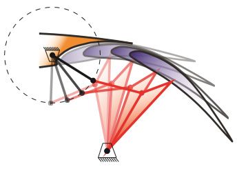
Aviation, 2020, 24(3): 123–126                                                                                                    129

                           (a)                                                              (b)

                                                                Figure 5. Position of high lift devices (a) 3 position leading edge
                                                                 slat operated by hinge mechanism during takeoff, landing and
                                                                 cruise modes of aircraft (Van Dam, 2002) (b) Variable camber
                                                                Krueger flap found on commercial aircrafts (Heap & Crowther,
                                                                2011) (c) Trailing edge flap position during takeoff, landing and
                                                                        cruise modes for DC-9 aircraft (Van Dam, 2002)
                           (c)

fixed vane and trailing edge flap are less than those used          tions are therefore small. However, with increase in num-
on double-slotted flaps. The aft-flap deflection on such            ber of flaps the beneficial effect provided by Fowler mo-
systems varies between 65° to 80°. Flap gaps are typically          tion is offset with increase in noise level during take-off
about 2% for the fixed vane and 1% of wing chord for the            or landing situations. The slotted configuration of leading
main and aft flaps. For best take-off, a higher glide ratio         and trailing-edge devices will impact the take-off glide
will increase gross weights using the maximum flap angle            ratio and subsequently the flow induced noise emanating
for single, double and triple-slotted flaps. The deflection         from them.
angle also varies typically between 10° and 20° with only                As noted earlier, the glide ratio for landing configura-
one slot. For low-gross-weight take-offs at high thrust-to-         tion can be significantly influenced by the type of high-
weight ratios, the take-off flap and landing flap deflection        lift system e.g. A Boeing 747-400 with low-aspect-ratio,
angles are nearly identical.                                        triple-slotted flaps produces more vortices from outboard
                                                                    flap region and are bound to have a low glide ratio dur-
2.1. Noise radiation from high lift systems                         ing landing than a Boeing 777 liner. Also, Krueger flaps
The high-lift system has an impact on airplane noise and            with span wise gaps produce additional drag at low in-
airplane performance. Referring to the sound pressure               cidence angles during approach due to fairings involved
level shown in Figure 6(a) multi-element aerofoils and              in flap operation. Therefore, the engines with high power
airframe noise sources are major contributors. Airframe             configuration produce more noise radiation and need to
noise is due to formation of vortices and turbulence as             maintain the three-degree glide slope angle on final ap-
result of separated flow regions and resonance induced in           proach. In contrast, the Airbus A330/340 with continu-
cavities. High-lift-system noise also impacts airplane glide        ous single-slotted flaps have a considerably high glide ratio
ratio and hence power output from engine. In this con-              and require a lower engine power in order to reduce noise
text, the take-off noise amplitude is different from other          radiation.
sources because take-off engine power is not influenced                  From Figure 6(a) the overall sound pressure level is
by glide ratio. Take-off noise with reduced load on en-             high between the leading edge slat and main element but
gine may affect the glide ratio since it varies with height         the peak sound level of 135dB is seen in slat cove region.
of aircraft above ground and location from measuring mi-            It must be noted that noise emission of vented leading-
crophone. Figure 6(b) shows the major noise sources on              edge slat airfoil is high due to interaction of vortex-gust
a landing aircraft equipped with two turbofan engines. It           with surface of airfoil and found to be more compared to
can be seen that flap and slat noise are important sources          sealed slat case (Huang, 2019). At the trailing edge of slat
of noise in addition to noise from landing gear, nose wheel         the sound pressure level can reach up to 111dB. Research
and engine sources. Usually slotted flaps are deployed only         efforts are focused on reduction of noise associated with
to a single-slotted configuration during take-off, and the          aircraft engines including airframe noise that has become
differences in glide ratio for different high-lift configura-       an important contributor to the overall noise, especially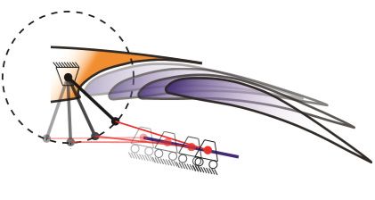
130                                      S. N. V. Neigapula et al. A study of high lift aerodynamic devices on commercial aircrafts

during approach for landing when the aircraft engines are             band noise. Finally, tonal noise produces narrow band
throttled down. Therefore, methods to reduce airframe                 peaks whose amplitudes are function of characteristic
noise involve advanced design of airframe, wing shape and             trailing edge geometry, angle of attack, Reynolds number,
materials which are essential for the development of quiet-           Strouhal number and state of the boundary layer flow
er civil aircrafts. A leading–edge slat is commonly used as           (Nukala & Maddula, 2020). Further, a tonal noise peak is
part of the high-lift devices deployed during landing and             quite often associated with vortex shedding behind a slat
take-off, and unsteadiness associated with flow separation            trailing edge with a finite thickness and produced due to
within the slat cove region is known to be one of the major           stall separation inside the slat cove region. For a typical
components of the airframe noise. The thin shear layer                wind tunnel scale model, the frequency of trailing edge
emanating from the slat cusp and its subsequent reattach-             vortex shedding noise tends to be significantly higher than
ment upstream of the slat trailing edge produces broad-               the dominant slat cove noise (Choudhari et al., 2014).

                                                                      2.2. Kinematic mechanisms on aircraft wings
                                                                       The types of kinematic mechanisms used commonly in a
                                                                      high lift system of aircraft in provided in Table 1, the type
                                                                      of motion necessary for the deployment or retraction of
                                                                      flaps hydraulically and a tradeoff reason for elimination.
                                                                           Most Boeing aircrafts are equipped with double slot-
                                                                      ted flaps for both leading and trailing edge of wing. This
                                                                      usually tends to increase the complexity of flap track sys-
                                                                      tem. So, to reduce the system complexity of a ventilated
                                                                      leading-edge slat, an adaptive dropped hinge flap (ADHF)
                                                                      has been implemented in A350 XWB-900 aircraft (Stru-
                                                                      ber, 2014). It eliminates fast actuation as well as the me-
                                                                      chanical link between flap and spoiler thereby reducing
                            (a)
                                                                      the weight of the actuation subsystem in high lift systems.
                                                                      The presence of flaps requires track kinematics which
                                                                      enables large fowler motion i.e. increase in wing area and
                                                                      camber to allow for adjustments of flap angles optimally
                                                                      during take-off situation. Flaps with hinge kinematics are
                                                                      less complex and light weight however, it offsets the high-
                                                                      lift configuration that can be aerodynamically optimized
                                                                      about a pivot point. Further, the pivot point needs to be
                                                                      positioned under wing in such a way to minimize cruise
                                                                      drag. Hinged flaps have ability to control the gap between
                                                                      the spoiler and the flap for laminar flows. To a large extent
                            (b)                                       it depends on hinge position close to the trailing edge of
                                                                      wing which tends to constrain the flap motion. It leads to
  Figure 6. Illustration of noise radiation (a) from 30P-30N          reduced wing area during take-off or landing manoeuvres.
multi element airfoil computed using CFD method (Lockhard
                                                                      So, a desired flap motion on hinge enables to control the
 & Choudhari, 2009) (b) measured from different sources on
 aircraft using microphone array method (Oerlemans, 2009)             resulting large gap through the spoiler actuator and re-
                                                                      duction in weight of the flap body and support structure.
                                                                      The complexity of kinematic mechanisms therefore affects

                                    Table 1. Types of kinematic mechanisms in a high lift system

                                Number of slots
      Kinematic                                                                                              Drawback
                                                          Airliner example     Type of motion
      mechanism                                                                                               reason
                      Leading edge       Trailing edge
Simple or dropped                                        Monoplane (ARV                         Aerodynamic efficiency, wear
                            1                     1                            Circular arc
hinge                                                    Super 2)
                                                                                                Reliability, wear, cost, aerodynamic
Hooked track                1                 2.3        B-757, 777            Circular arc
                                                                                                efficiency
                                                         A320/330/340 /        Straight &       Aerodynamic efficiency, depth of
Link/ track                 1                 2.3
                                                         Boeing                Circular arc     fairing
Four bar linkage            1                     1      B-767                 Circular arc     Reliability, wear, cost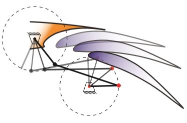
Aviation, 2020, 24(3): 123–126                                                                                                   131

efficiency and reliability of high-lift systems by influenc-                The dropped-hinge and four-bar mechanism on wing
ing aircraft weight and operation and maintenance cost,                 is usually equipped with a linear actuator or a rotary ac-
part count, and the number of hinges. In addition, a trade-             tuator. The link-track mechanisms are actuated by a rotary
off between high aerodynamic performance and reliable                   actuator while the hooked-track mechanisms are actuated
structural design depends on the design methodology to                  by a linear actuator. The four-bar mechanism is designed
increase efficiency at the expense of high direct cost.                  for three stages and typically retracted for take-off and
    Trailing-edge devices found on Boeing aircrafts in-                 landing position. Compared to the dropped-hinge model,
clude plain flaps to Fowler flaps with single, double, and              the support structure allows for additional joints aft of
even triple slots. In this regard, ailerons, elevators and              actuator attachment and part of the four-bar kinematics.
rudders can be considered as plain flaps. The complex-                  As a result modifying support structure dimensions and
ity of high-lift systems is high in Boeing 747 aircraft and             actuator attachment position affects the flap motion. Fur-
houses a variable camber Krueger flap and triple-slotted,               ther, the link-track mechanism offers more flexibility just
inboard and outboard trailing-edge flaps. This approach                 like the four-bar linkage. A track is used to provide trans-
has resulted in high levels of lift with relatively simpler op-         lation motion of flap while link determines the flap rota-
eration of kinematic devices in order to reduce acquisition             tion. A hooked-track mechanism is similar to link track in
and maintenance costs. Airbus wings are designed for the                which hooked track transmits the straight line motion of
high flight Mach-number, Ma-0.85 that requires a higher                 flap (Zaccai et al., 2016). As mentioned earlier, kinematic
sweep angle. The maximum quarter-chord sweep on the                     mechanisms in high lift systems use linear and rotary ac-
Mega-liner wing is 35.7° while on the A340-300 wing it is               tuators which can be driven by servo or stepper motor.
only 29.8° and on Douglas aircraft, DC-9 it is 24.5°. It sug-           It can be seen from Figure 7(a) that torque actuators are
gests that speed increase during cruise mode is possible                necessary to connect gearboxes to allow the torque to be
by a wing with a high sweep angle but it tends to increase              transmitted for desired flap motion. Figure 7(b) shows the
wing load. With increased wing loads, the maximum lift                  flap deflection and its rotation about hinge. In some cases
coefficient also rises at high flight Mach number. However,             cardan coupling also allows connecting shafts to transmit
high sweep wing can lead to reduced lift for low speed                  the rotational motion. The torque taken by each mecha-
manoeuvre and undesired pitch up behaviour of aircraft                  nism is reduced by the losses from a gearbox. Therefore, it
when the flow separation occurs on outboard region of                   can be said that dropped hinge and hooked-track mecha-
wing. Hence a droop nose device able to rotate on a hinge               nism allows the flap deflection to reach maximum angle
line is preferred choice both on inboard and outboard of                of 60° and reduces the gap and overlap in the take-off
wing’s leading edge. This favours maximum lift by delay-                configuration However, they are substantially lighter than
ing flow separation at higher incidence angles.                         the link-track and four-bar mechanism. Figure 7(c) illus-

                                             (a)                                              (b)

                                                                  (c)
      Figure 7. Illustration of (a) trailing edge flap actuation for a wing (b) aerodynamic loading action along quarter chord
      point of wing and flap motion about a hinge (adapted from Zaccai et al., 2016) (c) types of trailing edge flap kinematic
                                                       mechanisms (Bertels, 2012)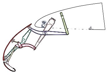
132                                    S. N. V. Neigapula et al. A study of high lift aerodynamic devices on commercial aircrafts

trates the dropped hinge, four bar linkage and link/track         σ, γ on each panel are evaluated by solving the algebraic
kinematic mechanisms with flap positions during actua-            system of equations defined by influence coefficients. The
tion. Due to its low weight and low power consumption,            solution of equations for a given geometry is achieved us-
the dropped-hinge mechanism has low overall system                ing influence coefficients which vary according to the flow
weight. Further, in terms of low part count and number of         configuration i.e. angle of attack and Reynolds number.
hinges the maintenance cost is also reduced significantly.        Using the influence coefficients, the tangential velocity
Despite the link-track mechanism is a heavy mechanism,            vector and pressure coefficient is obtained by integrating
it offers higher aerodynamic performance compared to              the source and vortex strengths for each panel. The tan-
others and requires a relatively small actuation load. A          gential velocity vector field over the airfoil surface is calcu-
detailed tradeoff analytic study on compensating the sys-         lated using the known values of influence coefficients on
tem weight and aerodynamic performance indicators such            every panel i.e. Normal (Cn) and tangential (Ct) directions
as, CLmax, glide ratio, maximum take-off weight (payload)         represented by matrix, M, source and vortex strength ma-
and direct cost is beyond the scope of present study.             trix A and vertical velocity components matrix B, defined
                                                                  for each panel. The tangential velocity vector is used to
3. Case: surface pressure distribution of 30P-30N                 determine the surface pressure coefficient along the chord
multi-element airfoil using 2D panel method                       length of the airfoil surface. It can be noted that panel
                                                                  method utilizes two essential boundary conditions viz.
As mentioned in introduction, CFD based computational             impermeable boundary condition in which the normal
methods involve setting up computational domain for               derivative of the velocity potential function is zero. The
given flow condition and mesh generation for a given ge-          other is known as Kutta condition defined for the trailing
ometry. Such method is accurate in the prediction of the          edge panels. Kutta condition is valid for all airfoils with
aerodynamic performance characteristics and turbulent             sharp trailing thickness for which flow over the trailing
flow field by solving unsteady non-linear Navier-Stokes           edge leaves smoothly (Dwivedi et al., 2019; Bhargava et al.
equations combined with turbulence models (Rahman                 2017). Further, it is important to note that bound circu-
et al., 2017; Jain & Mohammad, 2018) The size of compu-           lation surrounding the airfoil nullifies the trailing edge
tational domain may vary with complexity of geometry,             vortex strength downstream of wing in accordance with
type of flow and boundary conditions which can be ex-             Kelvin-Helmholtz hypothesis. Hence, in panel method, a
tended to near and far field. However, in panel methods,          uniform circulation distribution at every control point of
pressure distribution, velocity field and aerodynamic per-        a panel is assumed for a given flow condition. For large
formance parameters such as lift, drag coefficients can be        positive angle of attack, aerofoil experiences the flow
easily analyzed. Even though basic panel methods are suit-        separation close to leading edge and forms leading edge
able for characterizing potential flows it can be also be ex-     vortex (LEV) within the laminar boundary layer (Alsah-
tended to viscous flows to predict results faster than CFD        lan & Rahulan, 2017). It must be noted that flow separa-
methods for simple and complex geometries (Haughton               tion is caused due to the adverse pressure gradient in the
& Carpenter, 2013).                                               boundary layer when the shear stress exceeds the velocity
    In this work, 2D vortex panel method has been imple-          gradient close to wall or boundary (White, 2011; Bhargava
mented for 30P-30N airfoil to evaluate pressure coefficient       et al., 2019a, Bhargava et al., 2019b). On the other hand,
for a Reynolds number of 9 million at 16° angle of attack.        for any given angle of attack the flow separation occurs to-
The free stream velocity corresponding to Re-9 million            wards trailing edge and result as formation of trailing edge
is 58m/s. To validate our work, results from Dong and             vortex (Bhargava et al., 2020). The trailing edge vortex im-
Zhang (2012) and Anderson et al. (1995) has been used.            pacts the maximum lift coefficient generated on aircraft
A snapshot of the computational panel method algorithm            wing along span wise direction. The strength of vortex
implemented using MATLAB routine is shown in Figure 8             causes downwash on the wing due to higher induced drag
and Figure 9(a) shows the basic geometry of 30P30N air-           acting on the suction surface of wing than on the pressure
foil and Figure 9(b) illustrates the definition of deflection     surface (NASA Glenn Research Centre, 2019).
angles for flap, flap-gap and overlap distances at leading            Therefore, most aircrafts are fitted with active flow con-
and trailing edge for 30P30N implemented for study. To            trol devices along the span as well as rakes or tip fences
compute pressure coefficient distribution, the geometric          near the wing tip. The raked wing tip ensures starting vor-
settings for 30P30N are assumed: slat angle – 30° (δs in          tex leaving the trailing edge causes the induced velocity
Figure 9(b)), flap angle –30° (δf ), slat gap – 2.9% main         to produce downwash at sufficient distance away from the
chord (Gs), flap gap –1.25% main chord (Fs), slat over-           wing tip rather than on the wing span region. A series of
hang: –2.5% main chord (Os), flap overhang: 0.25% main            such continuous shed vortices away from wing span form
chord (Of ).                                                      a horse-shoe vortex structure behind the trailing edge. Fur-
    The length of panel is defined by node or end points          ther, the lift produced on wing is affected by angle of attack
while the source or vortex strengths for each panel is cen-       distribution along the wing span as well as the thickness
ter at mid or control points along with unit tangential and       to chord ratio of airfoil. A boundary layer is a region close
normal vectors for describing the velocity components on          to wall where the viscous forces are dominant. This region
the panel surface. Unknown source and vortex strengths            can be further divided into sub layers known as laminar
Aviation, 2020, 24(3): 123–126 133
Start
Read airfoil coordinates
Input data
Assign matrices for Divide the aerofoil surface into Initialize flow velocity &
Velocity vectors finite number of panels & define angle of attack
Influence coefficients apply boundary conditions
Assign the unit vectors for each panel
Calculate the effective distance between the
control points using boundary condition values
Assign velocity components on each panel
using unit vectors
A is unknown
source & vortex Calculate the normal and tangential influence
strengths vector coefficients for each panel, stored in matrix M
M. A = B
Solve for Evaluate the resultant tangential velocity
A vector for entire aerofoil surface
No Yes
Compute the values for Cp & CL, CD
Plot the outputs
End
Figure 8. Computational routine of 2D panel method implemented in MATLAB (Dwivedi et al., 2019)134 S. N. V. Neigapula et al. A study of high lift aerodynamic devices on commercial aircrafts
0.5 0.5
0.4 0.4
0.3 0.3
0.2 0.2
Gs
Main element Fs
0.1 0.1
0 0
y/c
y/c
s f
Os
–0.1 Flap –0.1 c Of
Slat
–0.2 –0.2
–0.3 –0.3
–0.4 –0.4
–0.5
0 0.2 0.4 0.6 0.8 1 1.2
0 0.2 0.4 0.6 0.8 1 1.2
x/c
x/c
(a) (b)
Figure 9. Illustration of 30P30N airfoil (a) Geometry (b) leading edge slat, trailing edge flap along with
deflection angles with respect to chord line
14 Laminar flow
separation
12
10 Transition to turbulence
8
Panel
–Cp [–]
6 Relaminarization Exp (Anderson W.K et al)
CFD (Dong Li, Zhang)
4
2
0
–0.2 0 0.2 0.4 0.6 0.8 1 1.2 1.4
–2
x/c [–]
Figure 10. Comparison of pressure coefficient distribution computed using 2D panel method for 30P-30N airfoil with
CFD results of Dong and Zhang (2012) and experiment results of Anderson et al. (1995) at 16° angle of attack,
Mach-0.2, Re-9 million
sub layer, log layer and outer turbulent layer in which the increased pressure recovery at trailing element. However,
defects in velocity profile are dominant. For laminar at- this pressure recovery is lowered due to high velocity on
tached flows, the shear stress is linearly proportional to suction surface and when a new thin boundary layer starts
the velocity gradient which suggests that pressure gradient to grow on trailing element that has potential to withstand
remains in favorable state until a critical point known as adverse pressure gradient. This is known as damping effect
inflexion is attained away from boundary. However for tur- since the pressure peaks on trailing elements are reduced
bulent flows the velocity profile is governed by a power law in such a way that wakes of individual elements merge to
for which turbulent kinetic energy dominates in a direc- form a confluent boundary layer which is thicker com-
tion opposite to free stream flow. This results in an adverse pared to ordinary boundary layer (Van Dam, 2002; Heap &
pressure gradient which has sufficient energy to separate Crowther, 2011). These flow mechanisms on multielement
the flow from the wall and thereby forms a vortex of finite airfoils tend to initiate transitions at a fixed or variable lo-
strength. So, the presence of slots or gaps in multi-element cations along chord and depend on the leading edge sweep
airfoil flows produces circulation and also responsible for angle, Reynolds number and surface roughness. In Figure
producing lift on individual elements. It must be noted that 10 laminar flow separation is observed at 15% x/c followed
direction of circulation on leading edge slat is opposite to by a transition to turbulence at 19% x/c location. This leads
that of trailing element. This causes a reduction of pressure to reduction in the maximum lift at high flight Reynolds
recovery and suction peak of trailing element which leads number. Howver, further downstream of chord, the relami-
to delayed flow separation and hence called slat effect. On narization of flow occurs at 25% x/c due to strong horizon-
the other hand circulation effect on leading edge of main el- tal acceleration or steeper favorable pressure gradient and
ement causes increased lift and aerodynamic loading with compensates the loss of lift. The lift loss varies with flightAviation, 2020, 24(3): 123–126 135
Reynolds number, increased flap distance and wing sweep Funding
angle parameters. A flap and slat deflection angle of 30° is
There is no funding for this project.
used for computing the Cp distribution and the results of
the panel method are in better agreement wih CFD results
from Dong and Zhang (2012) as well as with experiment Author contributions
values of Anderson et al. (1995) for high flight Reynolds Swamy Naidu N. V. – Conceptualization, review and edit-
number, Re-9 million. ing, Satya Prasad Maddula – Literature survey, code de-
velopment and drafting, Vasishta Bhargava – Literature
Summary and conclusions survey, methodology, validation and drafting.
This paper discussed about high lift devices on modern
aircraft and its importance on flight performance of air- Disclosure statement
craft. The following conclusions can be made: Authors declare no conflict of interest.
1. The presence of high lift devices either at inboard or
outboard regions along aircraft wingspan improves References
the aerodynamic and flight performance signifi-
cantly. Fowler and Krueger flaps show a remarkable Anderson, W. K., Bonhaus, D. L., McGhee, R., & Walker, B.
increase in maximum lift coefficient up to 100% as (1995). Navier-Stokes computations and experimental com-
parisons for multi-element aerofoil configurations. Journal of
the no of slots on wing is increased. The maximum Aircraft, 32(6), 1246–1253.
lift coefficient has direct impact on take-off, landing Alsahlan, A. A., & Rahulan, T. (2017). Aerofoil design for un-
performances of aircraft. manned high altitude aft-swept flying wings. Journal of Aero-
2. The shape of wing tips for commercial aircrafts show space Technology and Management, 9(3), 335.
significant influence on the span wise wing loading https://doi.org/10.5028/jatm.v9i3.838
during cruise mode. For reducing the downwash on Bertels, F. G. A. (2012). Design framework for flap system kin-
ematics; a knowledge-based engineering application (Master
wing span, the wing tips are swept back and out of
thesis). Delft University of Technology.
plane direction to reduce vortex drag on wing and Bhargava, V., Dwivedi, Y. D., & Rao, P. M. V. (2017). Analysis of
fuel consumption on long range flights. The aspect multi-element airfoil configurations: a numerical approach.
ratio of wing is key design feature to improve the MOJ Applied Bionics and Biomechanics, 1(2), 83–88.
flight Mach number for long range flights. High as- https://doi.org/10.15406/mojabb.2017.01.00012
pect ratio wings show reduced skin friction drag but Bhargava, V., Samala, R., & Anumula, C. (2019a). Prediction of
dramatically increase pressure drag and contribute broadband noise from symmetric and cambered airfoils. IN-
CAS Bulletin, 11(1), 39–51.
to the fuel efficiency of aircrafts. https://doi.org/10.13111/2066-8201.2019.11.1.3
3. Ascent or descent rate during take-off or landing Bhargava, V., Rahul, S., & Maddula, S. P. (2019b, June). Empirical
stages are function of thrust to weight ratio, aero- method of determining vortex induced aerodynamic noise
dynamic performance and maximum lift coefficient from wind turbine blades: A computational approach. Paper
and vary with no of slots deployable on aircraft presented at the 48th International congress and exhibition on
wing. The total drag on aircraft wing during opera- noise control engineering. Madrid, Spain.
https://doi.org/10.3849/aimt.01295
tion can be obtained using the vector addition of no
Bhargava, V., Kasuba, S., Maddula, S. M., Jagadish, D., Khan,
of flaps, slats; landing gear, pressure drag and wave Md. A., Padhy, C. P., Chinta, H. P., Chekuri, C. S. V., &
drag components. Dwivedi, Y. D. (2020). A case study of wind turbine loads and
4. The kinematic mechanisms play major role to con- performance using steady state analysis of BEM. International
trol the motion of flaps and slats on aircraft wings. Journal of Sustainable Energy.
Four bar linkage mechanism with a circular arc mo- https://doi.org/10.1080/14786451.2020.1787411
Catalano, F. M., Ceron, E. D., & Greco, P. C. (2012). Trailing edge
tion is most suited in terms of aerodynamic efficien-
treatment to enhance high lift system performance. 28th Inter-
cy of an aircraft wing while the simple or dropped national Congress of the Aeronautical Sciences (ICAS). Turkey.
hinge mechanism is cost efficient due to its low part Chernyshev, S. L., Iyapunov, V. S., & Wolkov, A. V. (2019). Mod-
count and simplicity of operation. ern problems of aircraft aerodynamics. Advances in Aerody-
namics, 1, 7. https://doi.org/10.1186/s42774-019-0007-6
Choudhari, M., Murayama, M., Nakakita, K., Yamamoto, K.,
Acknowledgements Hiroki, U., & Ito, Y. (2014). Experimental study of slat noise
Authors would like to thank the reviewers and editors from 30P30N three element high lift airfoil in JAXA hard
wall low speed wind tunnel. 20th AIAA/CEAS Aero-acoustics
who provided useful comments in improving the quality
Conference. Atlanta, GA. https://doi.org/10.2514/6.2014-2080
of the work. The authors would also like to thank Prof. Catalano, F. M., Ceron, E. D., & Greco, P. C. (2012). Trailing
Vijaya Srivastava, TEFL University, Lucknow campus for edge treatment to enhance high lift system performance. 28th
her valuable comments on the manuscript and English International Congress of the Aeronautical Sciences (ICAS).
language proof reading. Brisbane, Australia.136 S. N. V. Neigapula et al. A study of high lift aerodynamic devices on commercial aircrafts
Deng, N., Qu, Q., & Agarwal, R. K. (2018). Numerical study of Nukala, V., & Maddula, S. P (2020). Influence of rotor solidity
aerodynamics of rectangular multi-element wing in ground on trailing edge noise from wind turbine blades. Advances in
effect. Applied aerodynamics conference. Atlanta, Georgia. Aerodynamics, 2(15).
https://doi.org/10.2514/6.2018-4115 https://doi.org/10.1186/s42774-020-00036-9
Dong, L., & Zhang, Z. (2012, 23–28 September). Numerical in- NASA Glenn Research Centre. (2019). Shed Vortex. Aerody-
vestigation of flow over multi element airfoils with lift en- namics Index – Beginners Guide. https://www.grc.nasa.gov/
hancing tabs. 28th international Congress of the Aeronautical www/k-12/airplane/
Sciences. Brisbane, Australia. Oerlemans, S. (2009). Detection of aeroacoustic sound sources
Dwivedi, Y. D., Bhargava, V., Rao, P. M. V., & Donepudi, J. (2019). on aircraft and wind turbines (Doctoral thesis). University of
Aerodynamic performance of micro-aerial wing structures at Twente, Enschede. ISBN 978-90-806343-9-8.
low Reynolds number. INCAS Bulletin, 11(1), 107–120. Pascioni, K. A., Cattafesta, L. N., & Choudhari, M. (2014). An
https://doi.org/10.13111/2066-8201.2019.11.1.8 experimental investigation of the 30P-30N multi-element
FAA. (2019). Standard airworthiness certification regulations high lift airfoil. 20th AIAA/CEAS Aero-acoustics Conference.
part 25: airworthiness standards: transport category airplane. Atlanta, Georgia. https://doi.org/10.2514/6.2014-3062
https://www.faa.gov/aircraft/ Rahman, A. H. A., Mohd, N. A. R. N., Lazim, T. M., Mansor, Sh.
Haroon, K. (2011). The airline pilots forum and resource, princi- (2017). Aerodynamics of harmonically oscillating aerofoil at
ples of flight. https://www.theairlinepilots.com/forum low Reynolds number. Journal of Aerospace Technology and
Haughton, E., & Carpenter, S. (2013). Aerodynamics for engineer- Management, 9(1), 83–90.
ing students (6th ed.). Elsevier publishers. https://doi.org/10.5028/jatm.v9i1.610
Heap, H. & Crowther, B. (2011). A review of current leading edge Reckzeh, D. (2008). Aerodynamic design of theA400M high lift
device technology and of options for innovation based on flow system. 26th International congress of the aeronautical sciences.
control. University of Manchester, UK. Anchorage, Alaska, Canada.
Reckzeh, D. (2004). Aerodynamic design of airbus high-lift
Hess, J. L. & Smith, A. M. (1967). Calculation of potential flow
wings in a multidisciplinary environment. European Congress
about arbitrary bodies. Progress in Aerospace Sciences, 8,
on computational methods in applied sciences and engineering.
1–138. https://doi.org/10.1016/0376-0421(67)90003-6
ECCOMAS.
Huang, X. (2019). A theoretical study of serrated leading edges in
Rudolph, C. K. P. (1996). High lift systems on commercial sub-
aerofoil and vortical gust interaction noise. Advances in Aero-
sonic airliners. NASA Contractor Report 4746 –A463474LD
dynamics, 1, 6. https://doi.org/10.1186/s42774-019-0010-y
(LAS).
Husse, O. (2006). Best practices for fuel economy. ICAO Opera-
Sankar, L. N., Liu, Y., Englar, R. J., & Ahuja, K. K. (2001). Numer-
tional Measures Workshop. Montreal.
ical simulations of steady and unsteady aerodynamic character-
IATA. (2019). Jet fuel price monitor. IATA publication. https://
istics of a circulation control wing airfoil. American Institute of
www.iata.org/en/publications/economics/fuel-monitor/ Aeronautics & Astronautics.
Jain, S., Sitaram, N., & Krishnaswamy, S. (2015). Computational https://doi.org/10.2514/6.2001-704
investigations on the effects of Gurney flap on airfoil aerody- Struber, H. (2014). The aerodynamic design of the A350 XWB
namics. Hindawi Publishing Corporation. -900 high lift system. 29th Congress of International Council of
https://doi.org/10.1155/2015/402358 the Aeronautical Sciences. St Petersburg, Russia.
Jawahar, H. K., Azarpyevand, M., & Carlos, R. S. (2017). Experi- https://doi.org/10.1016/S1270-9638(02)00002-0
mental investigation of flow around three element high lift Van Dam, C. P. (2002). The aerodynamic design of multielement
airfoil with Morphing Fillers. 23rd AIAA/CEAS Aero-Acous- high lift systems for transport airplanes. Progress in Aerospace
tics Conference. Denver, Colorado. Sciences, 38(2), 101–144.
https://doi.org/10.2514/6.2017-3364 https://doi.org/10.1016/S0376-0421(02)00002-7
Jain, R., & Mohammad, U. (2018). CFD approach of Joukowski White, F. M. (2011). Fluid mechanics (7th Ed.). McGraw Hill
airfoil (T = 12%), comparison of its aerodynamic perfor- Publishers.
mance with NACA airfoils using k-ε turbulence model with Xuguo, Q., Peiqing, L., & Qiulin, Q. (2009). Aerodynamics of a
3 million Reynolds number. International Research Journal of multi-element airfoil near ground. Journal of Tsinghua Science
Engineering and Technology, 5(10), 1414–1418. and Technology, 14(S2), 94–99. ISSN 1007-0214.
Liebeck, R. H. (1978). Design of subsonic aerofoils for High lift. Zaccai, D., & Bertels, F. & Vos, R. (2016). Design methodology
Journal of Aircraft, 15(9). https://doi.org/10.2514/3.58406 for trailing edge high lift mechanisms. 5th CEAS Air & Space
Lockhard, P. D., & Choudhari, M. (2010). The effect of cross Conference. Netherlands.
flow on slat noise. 16th AIAA/CEAS Aero-acoustics Conference. https://doi.org/10.1007/s13272-016-0202-7
Stockholm, Sweden. https://doi.org/10.2514/6.2010-3835 Zhang, X., Qu, Q., & Agarwal, R. K. (2017). Computations of
Lockhard, D., & Choudhari, M. (2009). Noise radiation from a flow fields of an aerofoil and a wing with Gurney flap in
leading slat. 15th AIAA/CEAS aero-acoustics conference. Mi- ground effect. AIAA Aerospace Sciences Meeting. Kissimmee,
ami, Florida, US. https://doi.org/10.2514/6.2009-3101 Florida. https://doi.org/10.2514/6.2017-4466You can also read