OMNI - Base Comfort - Glideaway
←
→
Page content transcription
If your browser does not render page correctly, please read the page content below
OMNI
   OWNERS   MANUAL
   OWNERS MANUAL
MANUAL DE INSTRUCCIONES

    Comfort Base
                          ®

       Lifestyle Series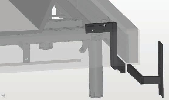
Contents

Safety Information............................................................................2
What Is Included................................................................................5
Assembly - Base................................................................................6
Assembly - Headboard Bracket.....................................................9
Location of Controls - Remote...................................................11
Operation - Main............................................................................11
Troubleshooting..............................................................................12
Available Accessories.....................................................................13
Specifications..................................................................................14
Technical Assistance......................................................................14
Service Requirements...................................................................14
Cleaning............................................................................................14
Warranty...........................................................................................15
Registration......................................................................................16

Spanish starts on page 17.
Español comienza en la página 17.

User Info
Please take a moment and write down the serial number in the space provided below, in
case you need to refer to it in the future. This information can be found by raising the head
section of the bed.

SKU:                CB05
Serial Number _________________________________________________________
This number will be required for future service claims.

                                                              2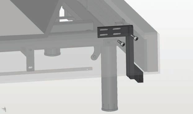
SAFETY INFORMATION
                         ATTENTION!
      IMPORTANT SAFETY INSTRUCTIONS. SAVE THIS MANUAL!
  PLEASE READ THESE INSTRUCTIONS THOROUGHLY BEFORE USING
  THIS PRODUCT. PROPER OPERATION OF YOUR ADJUSTABLE BED IS
    NECESSARY TO ENSURE THE LONG LIFE AND DURABILITY YOU
   EXPECT FROM A HIGH-QUALITY PRODUCT. THE MANUFACTURER
  HAS TESTED AND INSPECTED THIS PRODUCT PRIOR TO SHIPMENT.

ELECTRICAL SAFETY
Always unplug this adjustable bed from the electrical outlet before any cleaning or
maintenance of the bed frame. To safely disconnect, remove the plug from the outlet.
Keep cord away from heated surfaces. Use only indoors.

WARNING: TO PREVENT FIRE OR SHOCK HAZARD, DO NOT EXPOSE THIS UNIT TO MOISTURE.

Discontinue use of this adjustable bed and contact the manufacturer for repair if:
(1) it has a damaged cord or plug, (2) it is not working properly, (3) it has been dropped or
damaged.

FOR OPTIMAL SAFETY, YOUR ADJUSTABLE BED SHOULD BE PLUGGED INTO A SURGE
PROTECTOR (not supplied with this adjustable bed).

BATTERY PRECAUTIONS
Follow these precautions when using batteries in this device:
1. Warning – Danger of explosion if battery is incorrectly replaced. Replace only with the
   6LR61 9V batteries.
2. Be sure to follow the correct polarity when installing the batteries as indicated in the
   battery compartment. A reversed battery may cause damage to the device.
3. Do not mix different types of batteries together (e.g. Alkaline, Rechargeable and
   Carbon-zinc) or old batteries with fresh ones.
4. If the device is not to be used for a long period of time, remove the batteries to prevent
   damage or injury from possible battery leakage.
5. Do not try to recharge a battery not intended to be recharged; it can overheat and
   rupture. (Follow battery manufacturer’s directions.)

                                             3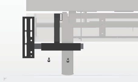
SAFETY INFORMATION
WARRANTY WARNING!
This bed is specifically designed to require no maintenance by you, the user. Any opening
or tampering with the control box, motors or hand controls (with the exception of
the battery compartment, if equipped) will void the warranty. Do not attempt to alter
component wiring or adjust or modify the structure of the product in any way or the
warranty will be void. Only those authorized may conduct repairs or part replacement on
your adjustable bed.

IN-HOME USE ONLY
This adjustable bed is designed exclusively for in-home use.

HOSPITAL/MEDICAL DISCLAIMER: This base is NOT designed for hospital or
medical use (In-Home or Commercial) and is NOT designed to meet medical or hospital
standards. Do not use this base with TENT TYPE oxygen therapy equipment or use near
explosive gases.

PRODUCT RATINGS
Lift Motor Restrictions: The lift motors in this bed are NOT designed to operate
continuously for more than one (1) minute over an eight (8) minute time period, or
approximately 12% duty cycle. To ensure reliable functionality and full life of this product,
do not attempt to exceed these limits.
NOTE: Attempting to circumvent or exceed this rating will shorten the life expectancy
of the product and may void the warranty.
Weight Restrictions: The recommended weight limits on our adjustable beds are:
Queen: 600 lb Full/XL: 500 lb Twin/XL: 400 lb (800 lb if using two twins as a King)

The structure of the bed will support the recommended weight when distributed evenly
across the bed.
The head section is not designed to individually support or lift this amount of
weight.
For optimal performance and integrity of structure, entering and exiting the adjustable bed
with the bed in the flat position is recommended.
NOTE: Exceeding the recommended weight restrictions could damage your
adjustable bed and void your warranty.

                                              4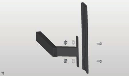
SAFETY INFORMATION

SMALL CHILDREN AND PETS WARNING
Immediately dispose of all packing materials, as they can pose a smothering risk to small
children and pets. Injury could also occur if children or pets are permitted to play on or
under the bed. Do not allow children to operate this bed without adult supervision.

LUBRICATION AND CLEANING
This product is designed to be maintenance free. The lift motors are permanently
lubricated and sealed—no additional lubrication is required. Do not apply lubricant to lift
motor lead screws or any nylon nuts or the base may inadvertently creep downward from
the elevated position.

LIFT WARNING
DO NOT SIT ON THE HEAD SECTION WHILE IN THE RAISED POSITION, OR DURING
LIFT OR LOWERING CYCLES.

MOVING AFTER INSTALLATION
Do not place adjustable bed base vertically on its head or foot sections. This may cause
injury to persons or damage to base.

WARNING!
To reduce the risk of burns, fire, electric shock, or injury to persons:
• Unplug from outlet before putting on or taking off accessories.
• Close supervision is necessary when this base is used by, or near children, invalids,
    disabled persons, or pets.
• Use this base only for its intended use as described in these instructions. Do not use
    attachments not recommended by the manufacturer.
• Never operate this base if it has a damaged cord or plug, is not working properly, has
    been dropped or damaged, or dropped in water.
• Keep the cord away from heated surfaces.
• Never drop or insert any object into any opening.
• Do not use outdoors.
• Do not operate where aerosol (spray) products are being used or where oxygen is
    being administered.
• To disconnect, remove plug from outlet.
• DO NOT USE NEAR PEOPLE USING OR WEARING MEDICAL DEVICES.
    FOR HOUSEHOLD/RESIDENTIAL USE ONLY.

                                             5
WHAT IS INCLUDED
Before discarding any packing materials, check the adjustable base shipping carton and
verify the following items are included:
(1) Base
(1) Foot Mattress Retainer
(attached to the base)
(4) Legs
(1) Remote Control
(1) AC Cord (not attached to the base)
(1) Power Supply
(not attached to the base)
(1) DC Power Cord
(1) Y-Cable (Twin XL only)
Also included:
(2) 9V Batteries
(1) Owner’s Manual
6ASSEMBLY - BASE
It is HIGHLY recommended to use two people for the installation of this product.
To assemble, please perform the following steps:
1 Carefully lift the base frame from the
shipping carton, keeping the unit top-
side-down. Remove the plastic wrapping
from the bottom to access the base.
To Control Box 2 Insert one end of the DC cord into the
power supply. Insert the other end with
locking clip into the Control Box. Lock the
Locking Clip Control Box using the locking clip.
3 Insert the AC cord into the power supply.
IMPORTANT: DO NOT PLUG THE BASE
INTO THE AC OUTLET YET.
4 Insert the legs into the threaded holes
at each corner of the base by inserting
the leg and rotating clockwise until tight.
There must not be any gap or wobble
in the leg in order to avoid risk of injury
or damage to the base which may void
warranty. Motor-to-DC
Cable
REMOTE
DC Power Cord
Motor-to-Remote
Cable 5 Remove the remote from the box. Attach
the remote to the motor-to-remote
Power Supplycable
on the Head motor as shown. Slide until it
snaps for a secure connection.
Foot and
Head Motor
Connector To AC
Cables Outlet
Remote
Cable
7ASSEMBLY - BASE
Motor-to-Remote Cable CONNECTING TWO TWIN XL BASES TO
Motor-to-Remote
FORM A KING: If setting up two Twin XL
Motor-to-Remote
tor-to-Remote Cable bases to use with one king size mattress,
Cable
Cable connect the “female” end of the Y-Cable
to the remote and then the two “male”
ends to each base frame’s Head Motor
connector.
NOTE: Only one remote is used when
connecting as a King. Motor-
Y-Cable Cab
DC P
6 Finish removing the plastic packaging
from the base to orient into final position.
Remove the Mattress Retainer Bar from
the bottom of the base. Carefully rotate
Remote the base on its side, then lift and place on
Cable
legs. IMPORTANT: DOFoot NOTand LEAN THE
BED AGAINST THE INSTALLED
Head Motor LEGS TO
TURN OVER. Connector
Cables
7 Insert the Mattress Retainer Bar upright
as shown.
8 Replace the retainer clip securely.
8ASSEMBLY - BASE
BASE POWER SUPPLY
9 Turn the power supply upside down to
access the battery cover, then slide the
battery cover off.
10 Insert the two 9V batteries (included)
into the compartment and slide the
cover back on.
NOTE: The battery backup will allow
for the bed to be lowered if a power
outage occurs. It is not recommended
to do anything except lower the bed,
as the battery backup will not last if
the features are continually used.
11 Insert AC plug into an AC outlet having
100-240V AC, 50/60Hz.
NOTE: If attaching a headboard brackets
(available seperately) to the base, see the
included instructions. Otherwise, place the
AC Plug AC Outlet desired mattress onto the base and enjoy your
new adjustable base!
9Assembly
Assembly -not
- Head
Head Board
Board Bracket
Bracket
Headboard brackets may be standard with purchase of
IMPORTANT: The head board bracket must be assembled to adjustable
the base base
AFTERand
thecan
bedbe
purchased separately.
base has been See page
completely 16 to purchase.
assembled. After assembling the bed according to the
IMPORTANT: The head board bracket must bethe
owner’s manual, see this sheet to assemble assembled to the
head board base AFTER the bed
bracket.
base has been completely assembled. After assembling the bed according to the
Whatmanual,
owner’s is Included?
see this sheet to assemble the head board bracket.
Unpack the kitkitand
Unpack the andmake
makesure
surethe
thefollowing
followingisisincluded:
included:
Bed Attachment Horizontal Shaft Head Board Attachment Plate M8x16mm Hex Bolt
PART A PART B PART C PART D
Qty: 8
Qty: 2 Qty: 2 Qty: 2
M8 Bolt M8 Nut Washer 10 Zinc Allen Key
PART E PART F PART G PART H
Qty: 4 Qty: 4 Qty: 4 Qty: 1
1
Completely raise the Fig. 1
headsection of the bed
to access the frame to
which the headboard
bracket will mount.
Identify the two thread-
ed holes that will be used
to mount bed attach-
ment ( Part A) in Step #2
2
Line up the holes in the
bed attachment (Part A) Fig. 2 PART A
with the two threaded
holes on the bed base.
Make sure the horizontal
fitting of the bed attach-
ment (Part A) points
towards the inside of the
bed. Insert two screws PART D
(Part D) provided with the
kit into the threaded holes
and tighten with the Allen
key (Part H) provided with
the kit.
10Assembly - Head Board Bracket
3
Attach the head board Fig. 3 PART C
attachment plate (Part C)
PART G
to the horizontal shaft PART B
(Part B) using the two flat PART F PART E
head self locking screws
(Part E), two washers (Part
G) and two nuts (Part F)
provided with the kit.
4
Insert, from the
outside of the bed, Fig. 4
the horizontal shaft PART B
(Part B) into the
horizontal fitting of
the bed attachment
(Part A).
PART A
5
Adjust the position of
the head board Fig. 5
PART C
attachment plates (Part
C) to the right or the left
PART A
of the bed as desired by PART B
moving the horizontal
shaft (Part B) left and
right in the horizontal
fitting of the bed
attachment (Part A). PART D
Once positioned
correctly tighten screws
(Part D) to hold in place.
To adjust the position of the head board attachment plates (Part C)
vertically, loosen nuts and screws from step 3. Tighten when the
appropriate height for your head board is met.
Install the head board using the line of 3 oval holes on the outside
of the head board attachment plate.
WARNING: The end of the horizontal shaft (Part B) must always
extend beyond the end of the horizontal fitting of the bed
attachment! (Part A) (See Fig. 5 Arrow)
11LOCATION OF CONTROLS - REMOTE
Head Up Head Down
Lay Flat
OPERATION - MAIN
Press and hold the Head Up ( ) button
to raise the Head position. Release button
when desired position is reached.
Press and hold the Head Down ( ) button
to lower the Head position. Release button
when desired position is reached.
Press the FLAT ( ) button so the bed
is flat.
12TROUBLESHOOTING
In the event the Comfort Base’s base fails to operate, investigate the symptoms and
possible solutions provided below:
No features of the base • Unplug power cord, wait 30 seconds and plug in to reset
will activate. electronic components.
• Defective surge protection device or electrical outlet. Test
outlet by plugging in another working appliance.
• Electrical circuit breaker may be tripped. Check electrical
circuit breaker box to verify.
Head section will
• Base mechanism may be obstructed. Elevate base and
elevate, but will not
check for obstruction. Remove obstruction.
return to the horizontal
(flat) position. • Headboard may be too close to the edge of the mattress.
Verify that distance between headboard brackets and
mattress is sufficient. Adjust if required.
Head Lift Function has • Make sure that you are following the duty cycle of the
minor interference motor (do not operate more than one (1) minute over
during operation. an eight (8) minute period, or approximately a 12% duty
cycle).
• Press the lift buttons squarely and accurately.
13AVAILABLE ACCESSORIES
Item Part Number
High Profile Legs
(Overall Bed Height 18.5”) CB12LEG18.5
Multi-Height Low Profile
Leg (Overall Bed Height 8” CB12LEGEX8-11.5
or 11.5”)
Headboard Bracket Kit CB05075HBBRKT
To order an accessory, please call 1-855-581-3095
14SPECIFICATIONS
Weight Capacity........................................................................... Queen: 600 lb, Full/XL: 500 lb,
................................................................ Twin/XL: 400 lb (800 lb if using two twins as a King)
Power Input................................................................................................... AC100-240 50/60HZ
Power Transformer Output.......................................................................................... DC29V 1.8A
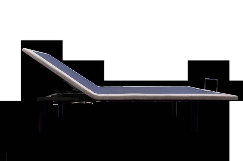
Overall Height of Bed........................................................................................................... 15 inches
Incline................................................................................................................................... Head - 65°
Included Accessories...............................Y Cable (Twin XL size only), Mattress Retainer Bar,
.........................................................Remote Control, Power Supply, AC and DC Power Cords,
.......................................................................... (2) 9V Batteries for Battery Backup, (1) Manual
TECHNICAL ASSISTANCE
For any questions, claims, or technical assistance, please contact Glideaway at
1-855-581-3095 or comfortbase@glideaway.com.
SERVICE REQUIREMENTS
Service technicians are not responsible for moving furniture, removing headboards and
foot boards, or any items required to perform maintenance on your adjustable bed. In the
event the technician is unable to perform service due to lack of accessibility, the service
call may be billed to the purchaser and the service will be re-scheduled.
CLEANING
Spot clean with upholstery shampoo, foam from a mild detergent, or mild dry cleaning
solvent. Pre-test a small inconspicuous area before proceeding. Do not saturate. Pile
fabrics may require brushing with a non-metallic bristle brush. Hot water extraction or
steam cleaning is not a recommended cleaning method.
15WARRANTY
Glideaway Comfort Base® Twenty Year Limited Warranty 1021.C
Glideaway Sleep Products (“Glideaway”) warrants to the original consumer purchaser that the motorized bed frame, motorized bed
foundation and adjustable bed (hereinafter referred to as “adjustable bed” or “adjustable beds”) are free from defects in workmanship
and material as provided herein. To the extent permitted by law, this Limited Warranty is not transferable and coverage terminates if
the original consumer purchaser (“purchaser”) sells or otherwise transfers the product.
If you wish to make a claim
You must contact the Glideaway dealer from whom the product was purchased, or if not available, Glideaway 1 855 581-3095
within thirty days of discovery of the problem with the serial number and the original sale receipt which identifies the date of
purchase. Any information or materials to be returned upon authorization should be sent to Glideaway at 8226 Lackland Road, St.
Louis, MO 63114.
What we will do
Year 1: Full coverage parts and labor warranty This adjustable bed is warranted against defects in the workmanship or materials
for a period of up to one (1) year from the date of purchase for adjustable beds bought new and for up to one (1) year from the
date of manufacture for those beds that were originally floor samples. Glideaway will send replacement parts (at no cost to the
purchaser) for any defective adjustable bed part to the purchaser, and Glideaway will pay all pre-authorized labor and transportation
costs associated with the repair or replacement of any parts which Glideaway determines to be defective. This one (1) year
warranty shall not apply if purchaser does not return any and all defective parts to Glideaway within 15 days of purchaser’s receiving
of replacement part(s).
Years 2-20 Limited Warranty: If the defect occurs in the second through twentieth year following purchase for adjustable beds
bought new and following the date of manufacture for adjustable beds that were originally floor samples, Glideaway will offer
replacement parts (upon terms and conditions set forth in this paragraph) for any mechanical adjustable bed part found to be
defective. Electronics, electrical components, drive motors and massage motors are excluded. Purchaser shall pay 1/19th of the
then current replacement cost of the defective part multiplied by the number of years the purchaser has owned the adjustable bed
for those beds bought new or multiplied by the number of years since the adjustable bed was manufactured for those adjustable
beds which were floor samples. Glideaway shall bear the remainder of the cost of the replacement part. This limited warranty shall
not apply if purchaser does not return any and all defective parts to Glideaway within 15 days of purchaser’s receipt of replacement
part. To the extent permitted by law, the purchaser shall bear all service, transportation, labor and shipping costs related to the
delivery and/or replacement of the defective part.
This limited warranty does not cover or apply to
This Limited Warranty does not apply: (a) to any damage caused to the adjustable bed by the purchaser; (b) if there has been any
unauthorized repair or replacement of the adjustable bed or parts; (c) if the adjustable bed has been mishandled whether in transit
or by other means, subjected to physical or electrical abuse or misuse, or otherwise operated in any way inconsistent with the
operation and maintenance procedures outlined in the Owner’s Manual, this limited warranty, and any other applicable document
published or approved by Glideaway; (d) in relation to damage to mattresses, fabric, cables, electrical cords or items supplied
by dealers (also known as retailers or resellers); (e) if there has been any unnecessary service calls, including costs for inhome
service calls solely for the purpose of educating the purchaser about the adjustable bed and/or for finding an unsatisfactory power
connection; (f) if the recommended weight restrictions (Twin/TXL/Split Queen/Split CA King: 400 pounds/ 181 kilograms, Full/FXL
Queen**: 500 Pounds/ 227 kilograms, Queen**: 600 Pounds/ 272 kilograms) and guidelines for proper distribution of weight as
stated in the Owner’s Manual are not followed; (g) for adjustable beds used in commercial type settings, such as but not limited to
dormitories, hotels and rentals.
**See owner’s manual for model specific information
Additional terms and conditions
No reimbursement will be made to the purchaser for the inconvenience, removal, installation, setup time, lack of use, shipping, or any
other costs or expenses not covered by this limited warranty. Glideaway holds no responsibility for in-home service on adjustable
beds. Purchaser should contact their dealer for any terms and conditions relating to purchaser’s in-home service if any.
Removal of product tag shall void warranty. The product tag has both the model and serial numbers, which serves as a means of
identification to establish one’s warranty rights. It is attached to the metal substructure visible when one lifts the head of the base.
TO THE EXTENT PERMITTED BY APPLICABLE LAW, THIS LIMITED WARRANTY REPLACES ALL OTHER REPRESENTATIONS,
WARRANTIES OR CONDITIONS, WHETHER EXPRESSED, IMPLIED OR LEGAL, ARISING FROM STATUTE, COURSE OF DEALING, USAGE
OF TRADE OR OTHERWISE INCLUDING ANY IMPLIED WARRANTIES OR CONDITIONS OF MERCHANTABILITY, DURABILITY, QUALITY
AND FITNESS FOR A PARTICULAR PURPOSE AND NO ONE IS AUTHORIZED TO ASSUME OR UNDERTAKE FOR GLIDEAWAY OTHER
LIABILITY IN CONNECTION WITH THE SALE OF THE PRODUCT. GLIDEAWAY SHALL NOT BE LIABLE FOR ANY DAMAGES, WHETHER
DIRECT, INDIRECT OR CONSEQUENTIAL OR ANY OTHER DAMAGES OF WHATEVER KIND, INCLUDING PERSONAL INJURIES OR
DAMAGE TO PROPERTY, EXCEPT AS PROVIDED HEREIN.
This warranty is made by Glideaway and is not made by or on behalf of its distributors, retailers or any other party. Some states
or provinces do not allow the exclusion or limitation of incidental or consequential damages or the exclusion of implied warranties
or the limitation on how long an implied warranty lasts, so the above limitations or exclusions may not apply to you. This warranty
gives you specific legal rights, and you may also have other rights which vary from state to state or province to province. To the
extent that the provisions of any applicable legislation expressly replaced, eliminate, amend, extend or prohibit any term or terms
contained in this warranty, such term or terms shall be accordingly replaced, eliminated, amended or extended, as the case may be,
in accordance with such legislation.
1021.C
16REGISTRATION
Thank you for purchasing a Comfort Base!
Register your Comfort Base by completing the form below or registering online at
www.glideaway.com.
Warranty Service
Filling out this form will help you obtain more efficient warranty service in case there is a
problem with your product.
Confirmation of Ownership
In case of an insurance loss such as fire, flood, or theft, your registration could serve as
your proof of purchase.
For Your Safety
Registering your Comfort Base will allow us to contact you in the unlikely event a safety
notification is required.
Please mail the form and send with a copy of your proof of purchase to:
Glideaway
Attn: Warranty/Claims Department
8226 Lackland Drive
St. Louis, MO 63114
Customer Info:
First Name:____________________________________________________________
Last Name: _ __________________________________________________________
Address: ______________________________________________________________
City: _________________________________________________________________
State: __________________________________ Zip: __________________________
Email: ________________________________________________________________
Phone Number: _ ______________________________________________________
Date of Birth:__________________________________________________________
Purchase Info:
Date of Purchase: ________________ Model Number:_ ______________________
Serial Number: ________________________________________________________
Did you buy online? Yes ____ No _____
Name of Retailer You Purchased from: ____________________________________
City of Retailer: ________________ State of Retailer:_____________________
Size of Base: ___________________ Price Paid: ____________________
17Contenido
Información de Seguridad............................................................18
¿Qué está incluido?.......................................................................21
Ensamblaje - Base..........................................................................22
Ensamblaje - Soporte del cabecero...........................................25
Ubicación de los controles - Control remoto..........................27
Funcionamiento - Principal..........................................................27
Resolución de Problemas..............................................................28
Accesorios Disponibles.................................................................29
Especificaciones..............................................................................30
Soporte Técnico..............................................................................30
Servicio.............................................................................................30
Limpieza............................................................................................30
Garantía.............................................................................................31
Registro.............................................................................................32
Información para el Usuario
Tómese unos minutos y anote el número de serie en el espacio provisto a continuación, en
caso de que lo necesite en el futuro. Encontrará esta información levantando la cabecera
de la cama.
SKU: CB05
Número de Serie _______________________________________________________
Necesitará este número para solicitar en el futuros servicio técnico.
18INFORMACIÓN DE SEGURIDAD
ATENCIÓN
INSTRUCCIONES IMPORTANTES DE SEGURIDAD. CONSERVE ESTE
MANUAL LEA DETENIDAMENTE ESTAS INSTRUCCIONES ANTES
DE UTILIZAR ESTE PRODUCTO. EL USO CORRECTO DE SU CAMA
REGULABLE ES NECESARIO PARA GARANTIZAR LA RESISTENCIA
Y DURABILIDAD QUE USTED ESPERA DE UN PRODUCTO DE ALTA
CALIDAD. EL FABRICANTE HA PROBADO E INSPECCIONADO ESTE
PRODUCTO ANTES DEL ENVÍO.
SEGURIDAD ELÉCTRICA
Siempre desenchufe esta cama regulable del tomacorriente antes de realizar trabajos de
limpieza o mantenimiento de la cama. Para desconectar de manera segura, quite el enchufe
del tomacorriente.
Evite el contacto del cable con superficies calientes. Utilice solo en interiores.
. ADVERTENCIA: PARA EVITAR INCENDIOS O PELIGROS DE DESCARGA, NO EXPONGA ESTA
UNIDAD A LA HUMEDAD.
Suspenda el uso de esta cama regulable y comuníquese con el fabricante para su
reparación si: (1) un cable o enchufe está dañado, (2) no funciona correctamente, (3) se
cayó o se dañó.
PARA UNA SEGURIDAD ÓPTIMA, LE ACONSEJAMOS QUE ENCHUFE SU CAMA REGULABLE
A UN PROTECTOR DE SOBREVOLTAJE (el cual no se incluye con esta cama regulable)
PRECAUCIONES CON LAS PILAS
Tenga en cuenta estas precauciones cuando utilice pilas con este dispositivo:
1. Advertencia - Peligro de explosión si la pila se reemplaza incorrectamente. Reemplace
únicamente con las pilas 6LR61 de 9V.
2. Asegúrese de respetar la polaridad correcta cuando coloque las pilas, tal como se indica
en el compartimiento de las mismas. Si coloca las pilas al revés, el dispositivo se puede
dañar.
3. No mezcle diferentes tipos de pilas (por ejemplo alcalinas, recargables y de zinc-carbono)
o pilas viejas con nuevas.
4. Si el dispositivo no se utiliza por un largo período de tiempo, quite las pilas para prevenir
daños o lesiones debido a una posible pérdida de las mismas.
5. No intente recargar pilas que no fueron diseñadas para ese fin; pueden recalentarse y
romperse. (Siga las instrucciones del fabricante de las pilas.)
19INFORMACIÓN DE SEGURIDAD
ADVERTENCIA DE GARANTÍA
Esta cama está específicamente diseñada para no requerir mantenimiento de su parte,
el usuario. No abra ni manipule indebidamente la caja de control, motores o controles
manuales (con excepción del compartimiento de las pilas, si estuviera equipado) dado
que ello anulará la garantía. No intente alterar el cableado de los componentes o ajustar o
modificar la estructura del producto de manera alguna dado que ello anulará la garantía.
Solo quienes estén autorizados podrán realizar trabajos de reparación o reemplazo de
piezas en su cama regulable.
SOLO PARA USO HOGAREÑO
Esta cama regulable está diseñada exclusivamente para uso hogareño.
EXENCIÓN DE RESPONSABILIDAD MÉDICA/ DE HOSPITALES: Esta base
NO está diseñada para uso médico u hospitalario (En el hogar o Comercial) y NO está
diseñada para cumplir con los estándares del hospital o médicos. No utilice esta base con
equipos de oxigenoterapia por carpa ni cerca de gases explosivos.
CLASIFICACIONES DEL PRODUCTO
Restricciones de los motores de elevación: Los motores de elevación de esta cama NO
están diseñados para funcionar de manera continua por más de un (1) minuto a lo largo
de un período de ocho (8) minutos, o aproximadamente un ciclo de trabajo del 12%. Para
garantizar un funcionamiento confiable y la vida plena de este producto, no intente exceder
estos límites.
NOTA: Intentar evadir o exceder esta clasificación acortará la vida útil
del producto y podría anular la garantía.
Restricciones de Peso: Los límites de peso recomendado para nuestras camas regulables son:
Queen: 600 libras 2 Plazas/XL: 500 libras 1 Plaza/XL: 400 libas (800 libras si se utilizan
dos camas de 1 plaza como una King)
La estructura de la cama soportará el peso recomendado cuando el mismo esté distribuido
uniformemente en toda la cama.
La cabecera de cama no están diseñados para soportar o levantar individualmente
este peso.
Para un rendimiento e integridad óptimos de la estructura, se recomienda subirse y bajarse
de la cama regulable con la cama en posición horizontal.
NOTA: Exceder las restricciones de peso recomendado podría dañar su cama
regulable y anular su garantía.
20INFORMACIÓN DE SEGURIDAD
AVERTENCIA PARA NIÑOS PEQUEÑOS Y MASCOTAS
Deseche inmediatamente todos los materiales del embalaje puesto que pueden presentar
riesgo de asfixia para niños pequeños y mascotas. Si permite que niños o mascotas jueguen
sobre o debajo de la cama, pueden resultar heridos. No permita que los niños operen esta
cama sin la supervisión de un adulto.
LUBRICACIÓN Y LIMPIEZA
Este producto está diseñado para no requerir mantenimiento. Los motores de elevación se
encuentran permanentemente lubricados y sellados -no se requiere lubricación adicional.
No aplique lubricante en los tornillos madre del motor de elevación o en las tuercas de
nylon, ya que la base podría deslizarse accidentalmente hacia abajo desde la posición
elevada.
ADVERTENCIA DE ELEVACIÓN
NO SE SIENTE SOBRE LA CABECERA DE CAMA CUANDO ÉSTA ES EN POSICIÓN
ELEVADA O DURANTE LA ELEVACIÓN O DESCENSO.
TRASLADO DESPUÉS DE LA INSTALACIÓN
No coloque la base de la cama regulable en posición vertical sobre su cabecera o pie. Ello
podría ocasionar lesiones a personas o dañar la base.
ADVERTENCIA
Para disminuir el riesgo de quemaduras, incendio, descarga eléctrica o lesión a personas::
• Desenchufe del tomacorriente antes de colocar o retirar accesorios.
• Se requiere supervisión de cerca cuando esta base sea utilizada por niños, personas
enfermas, personas con discapacidades o mascotas, o cerca de ellos.
• Utilice esta base sólo para su uso previsto, tal como se describe en estas instrucciones.
No utilice complementos no recomendados por el fabricante.
• Nunca opere esta base si un cable o enchufe está dañado, no funciona correctamente, se
cayó o dañó, o se cayó al agua.
• Evite el contacto del cable con superficies calientes.
• Nunca deje caer ni inserte objetos en ninguna abertura.
• No utilice la unidad en exteriores.
• No opere la unidad donde se estén utilizando productos de aerosol o donde se esté
administrando oxígeno.
• Para desconectar, retire el enchufe del tomacorriente.
• NO UTILICE CERCA DE PERSONAS QUE ESTÉN UTILIZANDO DISPOSITIVOS MÉDICOS.
SOLO PARA USO DOMÉSTICO/RESIDENCIAL.
21¿QUÉ ESTÁ INCLUIDO?
Antes de descartar los materiales de embalaje, revise la caja de envío de la base regulable y
verifique que se hayan incluido los siguientes artículos:
(1) Base
(1) Sujetador de colchón en la piecera
(adherido a la base)
(4) Patas
(1) Control Remoto
(1) Cable de CA (no adherido a la base)
(1) Alimentación
(no adherido a la base)
(1) Cable de Alimentación de CC
(1) Cable Y (Twin XL solamente)
También se Incluye:
(2) Pilas de 9V
(1) Manual
22ENSAMBLAJE - BASE
Es ALTAMENTE recomendado que dos personas realicen la instalación de este producto.
Para ensamblar, siga los pasos que se describen a continuación:
1 Levante cuidadosamente la base de la
caja de envío, manteniendo la unidad con
la parte superior hacia abajo. Retire el
envoltorio de plástico de la parte inferior
para acceder a la base.
A la caja de control
2 Introduzca un extremo del cable de CC en
la fuente de energía. Introduzca los otros
extremoS que tienen llaves de bloqueo
Llave de bloqueo
en la Caja de Control. Bloquee la Caja de
Control y utilizando las llaves de bloqueo.
3 Introduzca el cable de CA en la fuente de
energía.
IMPORTANTE: TODAVÍA NO ENCHUFE
LA BASE EN EL TOMACORRIENTE DE
CA.
4 Introduzca las patas en los orificios
roscados en cada esquina de la base,
insertando la pata y girando en el sentido
de las agujas del reloj hasta que esté bien
ajustada. No debe haber ningún espacio o
bamboleo en las patas para evitar el riesgo
de lesiones o daños a la base que puede
anular la garantía.
Motor a Cable
de CC
CONTROL REMOTO
Cable de Alimentación
Motor a Cable del
Control Remoto
5 Retire el control remotodede
CC la caja.
Conecte el control remoto al cable de
motor a control remoto en el motor para
Alimentación
la zona de cabeza tal como se muestra.
CablesDeslícelo
de hasta que se trabe en una
Conexión del
conexión segura.
Motor para
las Zonas de Al toma
Pies y Cabezas de CA
Cable del
Control Remoto
23ENSAMBLAJE - BASE
Motor a Cable del Control Remoto CONEXIÓN DE DOS BASES DE CAMA
Motor a Cable del
DE 1 PLAZA XL PARA FORMAR UNA
Motor-to-Remote
tor-to-Remote Control Remoto KING: Si se están armando dos bases
Cable
Cable de cama de 1 plaza XL para usarlas con
un colchón de tamaño King, conecte el
extremo “hembra” del cable Y al control
remoto y luego dos extremos “macho” a
cada conector del motor para la zona de
Cable Y cabeza del marco de la base. Motor-
Y-Cable Cab
NOTA: Solo se usa un control remoto al
conectar bases para formar una King.
6 Retire la barra sujetadora del colchón de la
parte inferior de la base. Termine de retirar
el envoltorio de plástico de la base para
DC P
orientarla en su posición final. De vuelta
la base cuidadosamente para ponerla en
Remote
Cable del Control posición lateral y luego levante y coloque
Cable
Remoto
las patas. IMPORTANTE: Foot NO
and APOYE LA
CAMA SOBRE LAS PATAS INSTALADAS
Head Motor
PARA DARLA VUELTA. Connector
Cables
7 Inserte la barra sujetadora del colchón en
posición vertical como se muestra.
8 Vuelva a colocar el gancho de retención
firmemente.
24ENSAMBLAJE - BASE
FUENTE DE ENERGÍA DE LA BASE
9 Dé vuelta la fuente de energía para
acceder a la tapa del compartimiento
de las pilas y luego deslice para retirar
la tapa.
10 Coloque las dos pilas de 9V (incluidas)
en el compartimiento y deslice la tapa
para volver a colocarla..
NOTA: La reserva de energía permitirá
que la cama pueda bajarse si ocurre un
corte de electricidad. No se recomienda
hacer otra cosa más que bajar la cama
puesto que la reserva de energía no
durará si se siguen utilizando el resto de
las funciones.
11 Introduzca el enchufe de CA en un
tomacorriente de CA que tenga 100-
240V CA, 50/60Hz.
NOTA: Si desea fijar un soporte de cabecero
(disponible por separado) en la base, remítase
Enchufe de CA Tomacorriente
de CA a las instrucciones. Caso contrario, coloque el
colchón sobre la base y ¡disfrute de su nueva
base regulable!
25Ensamblaje
Assembly - -Head
Soporte Board delBracket
Cabecero
IMPORTANT: The head board bracket must be assembled to the base AFTER the bed
Los soportes del cabecero tal vez no sean compatibles con la base ajustable y pueden
base has been
comprarse completely
por separado. assembled.
Consulte After
la pág. 35 assembling the bed
para saber cómo according to the
comprar.
owner’s manual,
IMPORTANTE: see thisde
El soporte sheet to assemble
cabecero the head board
debe ensamblarse con bracket.
la base LUEGO de haber
ensamblado completamente la base de la cama. Después de ensamblar la cama según el
What is Included?
manual del usuario, consulte esta hoja para ensamblar el soporte del cabecero.
Unpack the kit and make sure the following is included:
Desembale el kit y asegúrese de que esté incluido lo siguiente:
Tornillo hexagonal
Sujeción de la cama
Bed Attachment Eje horizontal
Horizontal Shaft Placa
Headde sujeción
Board del cabecero
Attachment Plate M8x16mm
M8x16mm Hex Bolt
PART D C
Parte
Parte
PART A A Parte
PART B B Parte
PART C C
Qty: 8
Qty: 2 Qty: 2 Qty: 2 Cantidad 2
Cantidad 2 Cantidad 2 Cantidad 2
Tornillo
M8 Bolt M8 Tuerca
M8 NutM8 Arandela
Washer 10de cinc 10
Zinc llaveKey
Allen Allen
PART E PART F PART G PART H
Parte
Qty: 4 E Parte
Qty: 4 F Parte
Qty: 4 G Parte
Qty: 1 H
Cantidad 4 Cantidad 4 Cantidad 4 Cantidad 1
11 Levante completamente
Completely
sección de la cabeza
raise thela
headsection of the
para acceder
de labed
cama
Fig. 1
to accessalthe marco
frame al cual
to se
montará el soporte
which the headboard del cabecero.
Identifique
bracket loswill
dosmount.
orificios
roscados que se usarán
Identify the two thread- para
montar la sujeción de
ed holes that will be la cama
used
(PartetoA) en el paso
mount bed attach- 2.
ment ( Part A) in Step #2
22 AlineeLine up the holes
los orificios in the
en la sujeción
de la cama (Parte A) con los A)
bed attachment (Part Fig. 2 PARTE
PART AA
with the
dos orificios two threaded
roscados de la base
holes on
de la cama. Asegúresethe bedde base.
que
Make sure the horizontal
la colocación horizontal de la
fitting
sujeción de laofcama
the bed attach-
(Parte A)
ment (Part A) points
apunte hacia la parte interna de
towards
la cama. the inside
Introduzca of the
dos tornillos
bed. Insert two screws
(Parte D) que vienen con el kit PARTE
PART DD
en los (Part D) provided
orificios roscados with the
y ajuste
kit into the threaded
con la llave Allen (Parte H) que holes
and el
viene con tighten
kit. with the Allen
key (Part H) provided with
the kit.
26Ensamblaje
Assembly -- Head
Soporte del Bracket
Board Cabecero
3
3
Adhiera la placa de sujeción
Attach the head board Fig. 3 PARTE
del cabecero (Parte C) al eje PART CC
attachment plate (Part C) PARTE
horizontal (Parte B) usando los PART GG
to the horizontal shaft PARTE
PART BB
dos tornillos de autobloqueo PARTE
PART EE
(Part B) using the two flat PARTE
PART FF
del cabezal (Parte E), dos
head self locking screws
arandelas (Parte G) y dos
(Part E), two washers (Part
tuercas (Parte F) que vienen
G) and two nuts (Part F)
con el kit
provided with the kit.
44
Insert, from the
outside
Introduzca, of the
desde bed,
afuera de la Fig. 4
cama,the horizontal
el eje horizontalshaft
(Parte PARTE
PART BB
B) en (Part B) into horizontal
la colocación the
horizontal
de la sujeción de lafitting
cama of
(Partethe
A). bed attachment
(Part A).
PARTE
PART AA
5
Adjust the position of
the head board Fig. 5
PARTE
PART CC
attachment plates (Part
C) to the right or the left
5 Ajuste la posición de las placas
of thedel
de sujeción
moving
bed as desired
cabecero
the
by
(Parte
horizontal
C) a la derecha o izquierda
PARTE
PART AA
PARTE
PART BB
de la shaft (Part B)
cama según left and
desee,
rightelineje
moviendo thehorizontal
horizontal
(Partefitting
B) a laofderecha
the bed e
izquierda en la colocación
attachment (Part A). PARTE
PART DD
horizontal de la sujeción
Once positioned de
la cama (Parte A).
correctly Una vez
tighten posicionado correctamente, ajuste los tornillos (Parte
screws
D) para(Part D) to hold in place.Para ajustar la posición de las placas de sujeción del
mantenerlo en su lugar.
cabecero (Parte C) en forma vertical, afloje las tuercas y tornillos del paso 3. Ajuste
To adjust the position of the head board attachment plates (Part C)
cuando se alcance la altura adecuada para su cabecero. Instale el cabecero utilizando
vertically, loosen nuts and screws from step 3. Tighten when the
la línea de 3 orificios ovalados en la parte exterior de la placa de sujeción del cabecero.
appropriateElheight
ADVERTENCIA: extremofordelyour head board
eje horizontal is met.
(Parte B) debe siempre extenderse más
Install the head board using the line of 3
allá del extremo de la colocación horizontal de la sujeciónoval holes
de la on
camathe outside
(Parte A) (Ver la
flechaofdethe head
la Fig. 5).board attachment plate.
WARNING: The end of the horizontal shaft (Part B) must always
extend beyond the end of the horizontal fitting of the bed
attachment! (Part A) (See Fig. 5 Arrow)
27UBICACIÓN DE LOS CONTROLES-CONTROL REMOTO
Levantar Cabeza Bajar Cabeza
Horizontal
FUNCIONAMIENTO - PRINCIPAL
Oprima y mantenga presionado el botón
Levantar cabeza ( ) para levantar la
posición de la cabeza Suelte el botón
cuando llegue a la posición deseada.
Oprima y mantenga presionado el botón
Bajar cabeza ( ) para bajar la posición de
la cabeza Suelte el botón cuando llegue a
la posición deseada.
Oprima el botón HORIZONTAL ( )
para que la cama se ponga en posición
horizontal.
28RESOLUCIÓN DE PROBLEMAS
Si la base de la Comfort Base no funciona, investigue las causas y posibles soluciones que
se detallan a continuación:
Las funcionalidades de la • Desenchufe el cable de alimentación, espere 30 segundos
base no se activan. y vuelva a enchufarlo para reiniciar los componentes
electrónicos.
• Dispositivo de protección contra sobrevoltaje o tomacorriente
defectuoso. Pruebe el tomacorriente enchufando otro aparato
que funcione.
• Es posible que el disyuntor haya saltado. Revise la caja del
disyuntor para verificar.
La cabecera de la cama • Es posible que el mecanismo de la base esté obstruido. Eleve
la base y verifique si existe algún tipo de obstrucción. Quite el
se eleva, pero no regresa obstáculo.
a la posición horizontal. • Es posible que el cabecero esté demasiado cerca del borde
del colchón. Verifique que la distancia entre el soporte del
cabecero y el colchón sea suficiente. Ajuste si fuera necesario.
La función Levantar • Asegúrese de respetar el ciclo de trabajo del motor (no lo
cabeza tiene una utilice durante más de un (1) minuto a lo largo de un período
interferencia de ocho (8) minutos, o aproximadamente un ciclo de trabajo
menor durante el del 12%).
funcionamiento. • Presione los botones de levantar firmemente y con precisión.
29ACCESORIOS DISPONIBLES
Ítem Número de parte
Patas largas
(Altura total de la cama 18,5”) CB12LEG18.5
Pata multialtura de bajo
perfil (Altura total de CB12LEGEX8-11.5
la cama 8”, 11”)
Kit de soporte del cabecero CB05075HBBRKT
Para realizar el pedido de un accesorio, comuníquese al
1-855-581-3095
30ESPECIFICACIONES
Capacidad de peso................................................. Queen: 600 libras, 2 Plazas/XL: 500 libras,
....... 1 Plaza/XL: 400 libas (800 libras si se utilizan dos camas de 1 plaza como una King)
Entrada de energía . ....................................................................................AC100-240 50/60HZ
Potencia de salida del transformador........................................................................ DC29V 1,8A
Altura total de la cama.................................................................................................... 15 pulgadas
Inclinación....................................................................................................................... Cabeza - 65°
Accesorios incluidos:..................................................... Cable Y (solo para cama de 1 plaza XL),
............................................................................... Barra sujetadora del colchón, Control remoto,
.................................................................... Fuente de energía, Cables de alimentación CA y CC,
.....................................................................(2) Pilas de 9V para reserva de energía, (1) Manual
SOPORTE TÉCNICO
Si tiene consultas, reclamos o precisa soporte técnico, comuníquese con Glideaway al
1-855-581-3095 o escriba a comfortbase@glideaway.com
SERVICIO
Los técnicos no tienen la responsabilidad de mover muebles, quitar cabeceros y pieceros
u otros artículos que deban retirarse para realizar mantenimiento en su cama regulable. Si
el técnico no puede prestar el servicio debido a falta de accesibilidad, la visita de servicio
écnico podría serle facturada al cliente y deberá programarse una nueva visita.
LIMPIEZA
Saque las manchas con shampoo para tapizados, espuma de detergente suave o solvente
de limpieza en seco suave. Pruebe previamente en un área pequeña poco visible antes de
proceder. No remoje. Las telas gruesas pueden requerir cepillado con un cepillo de cerdas
no metálicas. El uso de agua caliente o la limpieza a vapor no constituyen un método de
limpieza recomendado.
31GARANTÍA
Garantía Limitada Premium de veinte años de Glideaway Comfort Base™ 1021.C
Glideaway Sleep Products (“Glideaway”) garantiza al comprador consumidor original que el marco de la cama motorizado, la base de la cama
motorizada y la cama ajustable (en adelante denominados “cama ajustable” o “camas ajustables”) están libres de defectos de mano de obra y
material según lo dispuesto en el presente. Dentro de lo permitido por ley, esta Garantía limitada no es transferible y la cobertura finaliza si el
comprador consumidor original (“comprador”) vende o transfiere de otro modo el producto.
Si desea efectuar un reclamo
Debe comunicarse con el distribuidor de Glideaway a quien le compró el producto o, si no estuviera disponible, debe comunicarse con
Glideaway al 1 855 581-3095 dentro del plazo de treinta días de haber encontrado el problema, con el número de serie y el comprobante
original de compra en el que figura la fecha de compra. Toda información o materiales que deban ser devueltos, previa autorización, deben
enviarse a Glideaway, a 8226 Lackland Road, St. Louis, MO 63114.
Lo que nosotros haremos
Año 1: Garantía con cobertura total para piezas y mano de obra. Esta cama regulable cuenta con garantía contra defectos en la mano de
obra o materiales durante un período de hasta un (1) año a partir de la fecha de compra para camas regulables compradas sin estrenar y de
hasta un (1) año a partir de la fecha de fabricación para aquellas camas que originalmente se las utilizaba como muestras. Glideaway enviará
repuestos (sin cargo para el comprador) para cualquier componente de la cama regulable que presente defectos o fallas y correrán por cuenta
de Glideaway todos los costos de transporte y mano de obra previamente autorizados que se relacionen con la reparación o reemplazo de
cualquier pieza que según Glideaway presente defectos o fallas. Esta garantía de un (1) año no será de aplicación si el comprador no devuelve
las piezas defectuosas o que funcionan incorrectamente a Glideaway dentro del plazo de 15 días de que el comprador hubiere recibido los
repuestos.
Años 2 a 20: Garantía limitada. Si el defecto ocurre en el segundo a vigésimo año posterior a la compra de camas regulables sin estrenar
o posterior a la fecha de fabricación de camas regulables que originalmente se utilizaban como muestras, Glideaway ofrecerá repuestos
(conforme a los términos y condiciones que se establecen a continuación) para cualquier pieza mecánica de la cama que presente defecto.
Quedan excluidos los componentes electrónicos y eléctricos, los motores para masaje y los motores de elevación. El comprador deberá abonar
1/19 del costo de reemplazo de la pieza defectuosa que en ese momento se encontrare vigente multiplicado por la cantidad de años, durante
los cuales el comprador haya tenido la cama regulable para aquellas camas compradas a estrenar; o multiplicado por la cantidad de años,
durante los cuales el comprador haya tenido la cama regulable contados a partir de la fecha de fabricación de la cama regulable para aquellas
camas regulables que solían ser muestras. Correrá por cuenta de Glideaway la parte restante del costo del repuesto. Esta garantía limitada no
será de aplicación si el comprador no devuelve las piezas defectuosas a Glideaway dentro del plazo de 15 días de que el comprador hubiere
recibido los repuestos. En los casos en que sea de aplicación esta garantía limitada, correrán por cuenta del comprador todos los costos de
reparación, transporte, mano de obra, envío y manipulación que se relacionen con la entrega y/o reemplazo de las piezas defectuosas.
Esta garantía limitada no cubre
Esta garantía limitada no será de aplicación: (a) a daños ocasionados a la cama regulable por el comprador; (b) si ha tenido lugar cualquier
tipo de reparación o reemplazo no autorizado de la cama regulable o sus piezas; (c) si la cama regulable ha sido manipulada incorrectamente
durante su transporte o por otros medios, ha sido objeto de abuso físico o eléctrico, o fue utilizada de cualquier manera contraria a los
procedimientos de uso y mantenimiento que se describen en el Manual del usuario, en esta garantía limitada o en cualquier otro documento
pertinente publicado o aprobado por Glideaway; (d) en relación con daños al colchón, tela, cables, cables eléctricos o artículos suministrados
por distribuidores (también denominados revendedores); (e) si ha habido pedidos de servicio técnico innecesarios, incluidos los costos por
pedidos de soporte técnico domiciliario exclusivamente con el objeto de enseñarle al comprador acerca de la cama regulable y/o para encontrar
una conexión deficiente; (f) si no se respetan las restricciones de peso recomendado (1 Plaza/TXL/Split Queen/Split CA King: 400 libras/181
kgs, 2 Plazas/FXL Queen**: 500 libras/227 kgs, Queen**600 libras/272kgs) y las pautas para la correcta distribución del peso, tal como se
indica en el Manual de Uso; (g) para camas regulables utilizadas en entornos comerciales, como por ejemplo dormitorios universitarios, hoteles
y alquileres.
**Consulte el manual del usuario para ver la información específica del modelo.
Términos y condiciones adicionales
No se efectuará reembolso alguno al comprador por las molestias, retiro, instalación, tiempo de configuración, falta de uso, envío o cualesquiera
otros costos o gastos no cubiertos por esta garantía limitada. Glideaway no asume responsabilidad alguna por el servicio técnico domiciliario
de las camas regulables. Recomendamos que el comprador se comunique con su distribuidor para conocer los términos y condiciones
relacionados con el servicio técnico domiciliario disponible para el comprador, si hubiere.
El retiro de la etiqueta del producto anulará la garantía. La etiqueta del producto contiene el modelo y los números de serie, que sirven como
un medio de identificación para establecer los derechos de garantía. Esta etiqueta se encuentra adherida a la subestructura de metal, visible
cuando se levanta la cabecera de la base. .
DENTRO DE LO PERMITIDO POR LEY APLICABLE, ESTA GARANTÍA LIMITADA REEMPLAZA A TODAS LAS OTRAS DECLARACIONES,
GARANTÍAS O CONDICIONES, EXPRESAS, IMPLÍCITAS O LEGALES, QUE SURJAN DE LEYES, OPERACIONES, USO DE COMERCIO O QUE DE
OTRO MODO INCLUYAN GARANTÍAS IMPLÍCITAS O CONDICIONES DE COMERCIABILIDAD, DURABILIDAD, CALIDAD E IDONEIDAD PARA UN
FIN PARTICULAR. NADIE ESTÁ AUTORIZADO A ASUMIR POR GLIDEAWAY OTRA OBLIGACIÓN RELACIONADA CON LA VENTA DEL PRODUCTO.
GLIDEAWAY NO ASUME RESPONSABILIDAD POR DAÑOS, DIRECTOS, INDIRECTOS O INCIDENTALES U OTROS DAÑOS DE OTRO TIPO,
INCLUIDAS LESIONES PERSONALES O DAÑOS A LA PROPIEDAD, EXCEPTO LO DISPUESTO EN EL PRESENTE.
Esta garantía es otorgada por Glideaway y no es otorgada por ni en nombre de sus distribuidores, revendedores o cualquier otra parte.
Algunos estados no permiten la exclusión o limitación de daños incidentales o emergentes o la exclusión de garantías implícitas o la limitación
en relación con la duración de una garantía implícita, de manera que las mencionadas limitaciones o exclusiones pueden no aplicarse en su
caso. Esta garantía le otorga derechos legales específicos y usted podrá tener otros derechos que varían según el estado o la provincia. Si las
disposiciones de cualquier legislación aplicable expresamente reemplazan, eliminan, modifican, extienden o prohíben alguno de los términos
presentes en esta garantía, tales términos serán reemplazados, eliminados, modificados o extendidos según cada caso, en conformidad con
dicha legislación.
1021.C
32You can also read