AIR CONDITIONER PORTABLE - PPA1210M - Premium Levella
←
→
Page content transcription
If your browser does not render page correctly, please read the page content below
AIR CONDITIONER PORTABLE

           PPA1210M
Read This Manual
Inside you will find many helpful hints on how to use and maintain your air conditioner
properly. Just a little preventive care on your part can save you a great deal of time
and money over the life of your air conditioner. You'll find many answers to common
problems in the chart of troubleshooting tips. If you review our chart of Troubleshooting
Tips first, you may not need to call for service at all.

  ! CAUTION
  This appliance can be used by children aged from 8 years and above and persons
  with reduced physical, sensory or mental capabilities or lack of experience and
  knowledge if they have been given supervision or instruction concerning use of the
  appliance in a safe way and understand the hazards involved. Children shall not play
  the appliance. Cleaning and user maintenance shall not be made by children without
  supervision. ( be applicable for the European Countries )
  This appliance is not intended for use by persons (including children) with reduced
  physical ,sensory or mental capabilities or lack of experience and knowledge, unless
  they have been given supervision or instruction concerning use of the appliance by a
  person responsible for their safety. (be applicable for other countries except the
  European Countries )
  Children should be supervised to ensure that they do not play with the appliance.
  If the supply cord is damaged, it must be replaced by the manufacturer, its service
  agent or similarly qualified persons in order to avoid a hazard.
  The appliance shall be installed in accordance with national wiring regulations.
  Do not operate your air conditioner in a wet room such as a bathroom or laundry room.
  The appliance with electric heater shall have at least 1 meter space t o t he combustible
  materials.
  Contact the authorised service technician for repair or maintenance of this unit.
  Contact the authorised installer for installation of this unit.
CONTENTS
SOCIABLE REMARK
Sociable remark..................................................................................................................................2

SAFETY PRECAUTIONS
Safety rules .......................................................................................................................................3
Operating condition ...........................................................................................................................3
Electrical information .........................................................................................................................4

IDENTIFICATION OF PARTS
Accessories .......................................................................................................................................4
Names of parts...................................................................................................................................5

AIR CONDITIONER FEATURES
Electronic control operating instructions ...........................................................................................6

OPERATING INSTRUCTIONS
Operating instructions .......................................................................................................................7

INSTALLATION INSTRUCTIONS
Location ............................................................................................................................................9
Window kit installation ......................................................................................................................9
Exhaust hose installation ................................................................................................................12
Water drainage ................................................................................................................................13

CARE AND MAINTENANCE
Care and maintenance ....................................................................................................................14

TROUBLESHOOTING TIPS
Trouble shooting ..............................................................................................................................15

                                         NOTE
      The rating data indicated on the energy label is based
      on the testing condition of installing the un-extended
      air exhaust duct without adaptor A & B (The duct and
      the adaptor A & B are listed in the accessories chart
      of the Instruction Manual). See the right figure.

   1
SOCIABLE REMARK
When using this air conditioner in the European countries, the following informa-
tion must be followed:
DISPOSAL: Do not dispose this product as unsorted municipal waste. Collection of
such waste separately for special treatment is necessary.
It is prohibited to dispose of this appliance in domestic household waste.
For disposal, there are several possibilities:
A) The municipality has established collection systems, where electronic waste can be
disposed of at least free of charge to the user.
B) When buying a new product, the retailer will take back the old product at least free
of charge.
C) The manufacture will take back the old appliance for disposal at least free of charge
to the user.
D) As old products contain valuable resources, they can be sold to scrap metal dealers.
Wild disposal of waste in forests and landscapes endangers your health when
hazardous substances leak into the ground-water and find their way into the food chain.
CAUTION:
This appliance is not intended for use by persons (including children) with
reduced physical,sensory or mental capabilities, or lack of experience and
knowledge, unless they have been given supervision or instruction concerning
use of the appliance by a person responsible for their safety.
Children should be supervised to ensure that they do not play with the appliance.
2SAFETY PRECAUTIONS
Safety rules
To prevent injury to the user or other people and property damage, the following instructions must be
followed. Incorrect operation due to ignoring of instructions may cause harm or damage.
! Always do this Never do this
Do not operate your air conditioner in a wet room
Your air conditioner should be used in such a way such as a bathroom or laundry room.
that it is protected from moisture. e.g. condensation, Do not touch the unit with wet or damp hands or
splashed water, etc. Do not place or store your air when barefoot.
conditioner where it can fall or be pulled into water Do not press the buttons on the control panel with
or any other liquid. Unplug immediately. anything other than your fingers.
Always transport your air conditioner in a vertical Do not remove any fixed covers. Never use this
position and stand on a stable, level surface during appliance if it is not working properly, or if it has
use. been dropped or damaged.
Turn off the product when not in use. Never use the plug to start and stop the unit.
Always contact a qualified person to carry out Always use the switch on the control panel.
repairs. If the supply cord is damaged it must be Do not cover or obsturct the inlet or outlet grilles.
repaired by a qualified repairer. Do not use hazardous chemicals to clean or come
Keep an air path of at least 30cm all around the into contact with the unit. Do not use the unit in the
unit from walls, furniture and curtains. presence of inflammable substances or vapour such
If the air conditioner is knocked over during use, as alcohol, insecticides, petrol,etc.
turn off the unit and unplug from the mains supply Do not allow children to operate the unit
immediately. unsupervised.
Do not use this product for functions other than
those described in this instruction manual.
Energy Save
Use the unit in the recommended room size.
Locate the unit where furniture cannot obstruct the air flow.
Keep blinds/curtains closed during the sunniest part of the day.
Keep the filters clean.
Keep doors and windows closed to keep cool air in and warm air out.
Operating condition
The air conditioner must be operated within the temperature range indicated below:
MODE ROOM TEMPERATURE
COOL 17OC(62OF)~35OC(95OF)
DRY 13OC(55OF)~35OC(95OF)
HEAT(heat pump type) 5OC(41OF)~30OC(88OF)
HEAT(electrical heat type)IDENTIFICATION OF PARTS
WARNING For your safety
Do not store or use gasoline or other flammable vapors and liquids in the vicinity of this or any other
appliance.
Avoid fire hazard or electric shock. Do not use an extension cord or an adaptor plug. Do not remove
any prong from the power cord.
WARNING Electrical Information
Be sure the electrical service is adequate for the model you have chosen. This information can be found
on the serial plate, which is located on the side of the cabinet and behind the grille.
Be sure the air conditioner is properly grounded. To minimize shock and fire hazards, proper grounding is
important. The power cord is equipped with a three-prong grounding plug for protection against shock
hazards.
Your air conditioner must be used in a properly grounded wall receptacle. If the wall receptacle you intend
to use is not adequately grounded or protected by a time delay fuse or circuit breaker, have a qualified
electrician install the proper receptacle.
Ensure the receptacle is accessible after the unit installation.
Accessories
PARTS : PARTS NAME : QUANTITY :
Exhaust hose and ApaptorI and Adaptor B 1 set
(flat mouth or round mouth :depending on models)
or Window Slider Kit and bolt
Wall Exhaust Adaptor A( ) 1 pc
Adaptor B(round mouth)( ) 1 pc
Expansion Plug and wooden screw( ) 4/ pc
Foam seal 3/pc
AUTO
COOL
DRY
HEAT
MODE
SET TEMPERATURE( F )
SWING
ION
Remote Controller and Battery
RESET LOCK
1pc
TEMP
ECONOMY TIMER ON
ON/OFF FAN SPEED
DISPLAY
LED
TIMER OFF
(For remote control models only)
FAN
HIGH
MED
LOW
Drain hose( ) and drain hose adaptor( ) 1pc
NOTE: Optional parts( ), some models without.
Check all the accessories are included in the package and please refer to the installation instructions for
their usage.
NOTE: All the illustrations in this manual are for explanation purpose only. Your air conditioner
may be slightly different. The actual shape shall prevail.
4IDENTIFICATION OF PARTS
2 1
NAMES OF PARTS
Front
4
1 Operation panel
2 Horizontal louver blade
(swing automatically)
3 Caster
4 Carrying handle
(both sides)
3
Fig.1
Rear
5 Upper air filter
5 (Behind the grille)
6 Upper air intake
6 15
7 Air outlet
7
14 8 Drain outlet (only for Pump
8 heating model)
13
9 9 Power cord outlet
10 Power cord buckle (Used
10 only when storing the unit)
11 12
11 Bottom tray drain outlet
Fig.2
12 Power plug socket (Use
only when storing the unit)
13 Lower air filter
(Behind the grille)
14 Lower air intake
15 Drain outlet
5AIR CONDITIONER FEATURES
ELECTRONIC CONTROL OPERATING INSTRUCTIONS
Before you begin, thoroughly familiarize yourself with the control panel and remote controller
and all its functions, then follow the symbol for the functions you desire.
The unit can be controlled by the unit control panel alone or with the remote controller .
NOTE: This manual does not include Remote Controller Operations, see the packed with the unit for details.
OPERATION PANEL OF THE AIR CONDITIONER
(Optional)
9 8
7 6 5 4 4 3 2 1
(Optional) (ION is Optional)
Fig.3
NOTE: On some models SLEEP button is instead of ECO button.
5 MODE select button
1 POWER button Selects the appropriate operating mode.
Power switch on/off. Each time you press the button, a mode
is selected in a sequence that goes from
2 SLEEP/ECO button AUTO, COOL, DRY, FAN and HEAT(cooling
Used to initiate the SLEEP/ECO operation. only models without). The mode indicator
light illuminates under the different mode
3 FAN/ION button (ION is optional) settings.
Control the fan speed. Press to select the fan
speed in four steps-LOW, MED, HI and AUTO. 6 TIMER button
The fan speed indicator light illuminates under Used to initiate the AUTO ON start time and
different fan settings except AUTO speed. When AUTO OFF stop time program, in conjuction
select AUTO fan speed, all the fan indicator lights with the &+ - buttons. The timer on/off
indicator light illuminates under the timer
turn dark.
NOTE: Press this button for 3 seconds to initiate on/off settings.
ION feature.The ion generator is energized and will 7 SWING button
help to remove pollen and impur ities from the air, and (Applicable to the models with auto swing feature only)
trap them in the filter. Press it for 3 seconds again to Used to initiate the Autoswing feature.
stop the ION feature. When the operation is ON, press the
4 UP( +
) and DOWN( ) button - SWING button can stop the louver at
the desired angle.
Used to adjust (increasing/decreasing)
temperaturesettings in1 C /2F(or 1 F) increments 8 LED Display
in a range of 17 C/62 F to 30 C/88 F (or 86 F) Shows the set temperature in OC or
or the TIMER setting in a range of 0~24hrs. O
F and the Auto-timer settings.
The temperature display (Fahrenheit or Celsius) can be While on DRY and FAN modes, it shows
changed by pressing down the UP and DOWN buttons
on control panel Simultaneously. the room temperature.
NOTE: The control is capable of displaying
temperature in degrees Fahrenheit or degrees
Celsius. To convert from one to the other, press
and hold the Up and Down buttons at the same
time, for 3 seconds.
6
1
7OPERATING INSTRUCTIONS
Error codes and protection code: - Press the "MODE" button until the "DRY"
E1- Room temperature sensor error- indicator light comes on.
Unplug the unit and plug it back in. - Under this mode, you cannot select a fan
If error repeats, call for service. speed or adjust the temperature. The fan
E2- Evaporator temperature sensor error- motor operates at LOW speed.
Unplug the unit and plug it back in. - Keep windows and doors closed for the
If error repeats, call for service. best dehumidifying effect.
E3- Condenser temperature sensor error- - Do not put the duct to window.
Unplug the unit and plug it back in. If error
repeats, call for service (on some models). AUTO operation
E4- Display panel communication error- - When you set the air conditioner in AUTO
Unplug the unit and plug it back in. mode, it will automatically select cooling,
If error repeats, call for service. heating(cooling only models without), or
P1- Bottom tray is full - Connect the fan only operation depending on what
drain hose and drain the collected temperature you have selected and the
water away. If protection repeats, call room temperature.
for service. - The air conditioner will control room
9 FOLLOW ME/TEMP SENSING feature(optional) temperature automatically round the
NOTE:This feature can be activated from the temperature point set by you.
remote control ONLY. The remote control - Under AUTO mode, you can not
servesas a remote thermostat allowing for the select the fan speed.
precise temperature control at its location. FAN operation
To activate the Follow Me/Temp Sensing - Press the "MODE" button until the
feature, point the remote control towards "FAN " indicator light comes on.
the unit and press the Follow Me/Temp - Press the "FAN SPEED" button to
Sensing button. T he remote display is choose the fan speed. The temperature
actual temperature at its location. The cannot be adjusted.
remote control will send this signal to the - Do not put the duct to window.
air conditioner every 3 minutes interval
until press the Follow Me/Temp Sensing TIMER operation
button again.If the unit does not receive - When the unit is on, press the
the Follow Me/Temp Sensing signal during Timer button will initiate the Auto-off
any 7 minutes interval, the unit will beep to stop program, the TIMER OFF
indicate the Follow Me/Temp Sensing mode indicator light illuminates. Press the
has ended. UP or down button to select the desired
Operating Instructions time. Press the TIMER button again
within 5 seconds, the Auto-on start
COOL operation program is initiated. And the TIMER
- Press the "MODE" button until the "COOL" ON indicator light illuminates. Press
indicator light comes on. the up or down button to select the
- Press the ADJUST buttons "+" or " - " to desired Auto-on start time.
select your desired room temperature. The - When the unit is off, press the Timer
temperature can be set within a range of button to initiate the Auto-on start
17OC-30OC/62OF-88OF (or 86OF). program,press it again within five
- Press the "FAN SPEED" button to choose the seconds will initiate the Auto-off stop
fan speed. program.
HEAT operation(cooling only models without) - Press or hold the UP or DOWN
- Press the "MODE" button until the "HEAT" button to change the Auto time by
indicator light comes on. 0.5 hour increments, up to 10 hours,
- Press the ADJUST buttons "+" or " - " to then at 1 hour increments up to 24
select your desired room temperature. The hours. The control will count down
temperature can be set within a range of the time remaining until start.
17OC-30OC/62OF-88OF (or 86OF). - The system will automatically revert
- Press the "FAN SPEED" button to choose the back to display the previous temper-
ature setting if there is no operation
fan speed. For some models, the fan speed
in a five seconds period.
can not be adjusted under HEAT mode.
7OPERATING INSTRUCTIONS
- Turning the unit ON or OFF at any SLEEP/ECO operation
time or adjusting the timer setting Press this button, the selected temperature will
to 0.0 will cancel the Auto Start/ increase(cooling) or decrease(heating) by
O O O
Stop timer program. 1 C/2 F(or 1 F) 30 minutes.The temperature will
- When the malfunction (E1,E2,E3 then increase (cooling) or decrease (heating) by
O O O
or E4) occurs, the Auto Start/Stop another 1 C/2 F(or 1 F) after an additional 30
timed program will also be cancelled. minutes. This new temperature will be maintained
for 7 hours before it returns to the originally
selected temperature. This ends the Sleep/Eco
mode and the unit will continue to operate as
originally programmed.
NOTE: This feature is unavailabe under FAN or
DRY mode.
Other features
Auto-Restart(on some models)
If the unit breaks off unexpectedly due to the
power cut,it will restart with the previous
function setting automatically when the
power resumes.
Wait 3 minutes before resuming operation
Swing automatically After the unit has stopped, it can not berestarted
operation in the first 3 minutes. This is toprotect
the unit. Operation will automatically start after
3 minutes.
Air flow direction adjustment
The louver can be adjusted automatically .
Adjust the air flow direction automatically
(Fig.4):
When the Power is ON, the louver opens fully.
Press the SWING button on the panel or
remote controller to initiate the Auto swing
feature.
The louver willl swing up and down
automatically.
Fig.4 Please do not adjust the louver manually.
8INSTALLATION INSTRUCTIONS(optional)
INSTALLATION INSTRUCTIONS
Location
The air conditioner should be placed on a firm
foundation to minimize noise and virbration. For
safe and secure positioning, place the unit on a
smooth, level floor strong enough to support the unit.
B The unit has casters to aid placement, but it should
A
only be rolled on smooth, flat surfaces. Use caution
Fig.5 when rolling on carpet surfaces. Do not attempt to
A:30cm-100cm B: 30cm roll the unit over objects.
The unit must be placed within reach of a properly
rated grounded socket.
Never place any obstacles around the air inlet or
Horizontal
window outlet of the unit.
Allow 30cm to 100cm of space from the wall with
for efficient air-conditioning.
Window slider kit Installation
Window Slider Kit
Minimum:67.5cm(2.22ft).
Your window slider kit has been designed to fit most
Maxmum:123cm(4.04ft). standard Vertical and horizontal window
Fig.6 applications, However, it may be necessary for you to
improvise/modify some aspects of the installation
procedures for certain types of window. Please refer
to Fig. 6& Fig.7 for minimum and maximum window
openings.Window slider kit can be fixed with a bolt
(see Fig.7a).
Horizontal
window Note: If the window opening is less than the mentioned
minimum length of the window slider kit, cut that one
with a hole in it short to fit for the window opening.
Window Slider Kit Do never cut out the hole in window slider kit.
Minimum:67.5cm(2.22ft).
Maxmum:123cm(4.04ft).
Fig.7
bolt
Window slider kit
Fig.7a
9INSTALLATION INSTRUCTIONS(optional)
Installation in a double-hung sash
window
Foam seal A
(adhesive type)
1. Cut the foam seal(adhesive type) to the proper length and
attach it to the window stool. Fig.8
2. Attach the window slider kit to the window stool. Adjust the
Fig.8
length of the window slider kit according to the width of
window, shorten the adjustable window kit if the width of
window is less than 26.5 inches
Open the window sash and place the window slider kit on
the window stool. Fig.9
Window kit
3. Cut the foam seal(adhesive type) to the proper length
26.5 ~ 48.0 and attach it on the top of the window. Shown as in Fig.10
Window stool
4. Close the window sash securely against the window.
Fig.9
5. Cut the foam seal to an appropriate length and seal the
open gap between the top window sash and outer window
sash. Shown as in Fig.11.
Window kit
Window stool
Fig.10
Foam seal
Fig.11
10INSTALLATION INSTRUCTIONS(optional)
Installation in a sliding sash window
Foam seal A 1. Cut the foam seal(adhesive type) to the proper length and
(adhesive type)
attach it to the window frame. See Fig.12.
2. Attach the window slider kit to the window stool. Adjust the
length of the window slider kit according to the width of
Fig.12 window, shorten the adjustable window kit if the width of
window is less than 26.5 inches.
Open the window sash and place the window slider kit on
Window
the window stool. See Fig.13.
panel
26.5 ~ 48.0 3. Cut the foam seal(adhesive type) to the proper length
and attach it on the top of the window. Shown as in Fig.14.
4. Close the sliding sash securely against the window.
Fig.13
5. Cut the foam seal to an appropriate length and sea the
open gap between the top window sash and outer window
sash. Shown as in Fig.15.
NOTE:All the illustrations in this manual are for explanation
purpose only.Your unit may be slightly different. The
Fig.14 actual shape shall prevail.
Foam seal
Fig.15
11INSTALLATION INSTRUCTIONS
Exhaust hose installation:
The exhaust hose and adaptor must be installed or removed
in accordance with the usage mode.
COOL,HEAT(heat pump type) or AUTO Install
Fig.16a Fig.16b mode
FAN,DEHUMIDIIFY or HEAT(electrical heat type) Remove
mode
Hole seat
Hook
1. Install the adaptor B and adaptor I onto the exhaust hose as
shown in Fig.16a or Fig.16b. Refer to the previous pages for
window kit installation.
2. Resert the hook of the Exhaust hose into the hole seat of the
air outlet and slide down the Exhaust hose along the arrow
Fig.17 direction (See Fig.17) for installation.
The exhaust hose can be installed into the wall
(Not applicable to the units without adaptor A, expansion
plugs and wooden screws of Accessories ).
Expansion plug
position 1. Prepare a hole in the wall. Install the wall Exhaust adaptor A
onto the wall(outside) by using 4 expansion plugs and
Adaptor A wooden screws, be sure to fix thoroughly. (See Fig.18)
Adaptor
cap 2. Attach the Exhaust hose to wall Exhaust adaptor A.
Note:
Cover the hole using the adaptor cap when not in use.
max 120CM
The exhaust hose can be compressed or extended
min 30CM
moderately according to the installation requirement,
but it is desirable to keep the hose length to a minimum.
Fig.18 IMPORTANT:
DO NOT OVER BEND THE EXHAUST HOSE (SEE Fig.19)
CAUTION:
Make sure that there is no obstacle around the air outlet of
the exhaust hose (in the range of 500mm) in order to the
exhaust system works properly.
Fig.19
12INSTALLATION INSTRUCTIONS
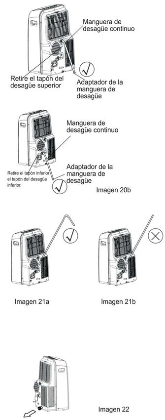
Water drainage:
- During dehumidifying modes, remove the upper
Continuous
drain hose drain plug from the back of the unit, install the drain
connector(5/8 universal female mender) with
3 4 hose(locally purchased). For the models
without drain connector, just attach the drain
Remove the hose to the hole. Place the open end of the
upper drain plug hose directly over the drain area in your basement
floor. Please refer to Fig.20a.
Fig.20a
Continuous - During heating pump mode, remove the lower drain
drain hose plug from the back of the unit, install the drain
connector(5/8 universal female mender) with
3/4 hose(locally purchased). For the models
drain hose without drain connector, just attach the drain
Remove the adaptor
lower drain plug
Fig.20b hose to the hole. Place the open end of the
hose adaptor directly over the drain area in your
drain hose
adaptor basement floor. Please refer to Fig.20b.
NOTE: Make sure the hose is secure so there are
delive ry liftCARE AND MAINTENANCE
Upper filter CARE AND MAINTENANCE
(take out)
IMPORTANT:
Remove the 1) Be sure to unplug the unit before cleaning or servicing.
screw ,then 2) Do not use gasoline, thinner or other chemicals to clean
take the lower the unit.
filter out. 3) Do not wash the unit directly under a tap or using a hose.
It may cause electrical danger.
Fig.23 4) If the power cord is damaged, it should be repaired by
manufacture or its agency.
Upper filter
(install)
1. Air filter
- Clean the air filter at least once every two weeks to prevent
inferior fan operation because of dust.
Install the lower - Removal
filter by using This unit has two filters. Take the upper filter out along the
the screw.
the arrow direction (Fig.23),then take the filter down.
Remove the lower filter by loosening the screw, taking out
Fig.24 the filter as shown in Fig.23.
- Cleaning
Wash the air filter by immersing it gently in warm water
(about 40OC/104OF) with a neutral detergent. Rinse the filter
and dry it in a shady place.
- Mounting
Install the upper air filter after cleaning , and install the lower
filter by using the screw (see Fig.24).
2. Unit enclosure
- Use a lint-free cloth soaked with neutral detergent to clean
the unit enclosure. Finished by a dry clean cloth.
3. Unit idle for a long time
- Remove the rubber plug at the back of the unit and attach
a hose to drain outlet. Place the open end of the hose
Buckle directly over the drain area in your basement floor
(See Fig.20 & 21).
Power - Remove the plug from the bottom drain outlet, all the water
cord in the bottom tray would drain out (See Fig.22).
Power plug - Keep the appliance running on FAN mode for half a day in
Power plug a warm room to dry the appliance inside and prevent mold
socket forming.
- Stop the appliance and unplug it, wrapped the cord and
Fig.25 bundle it with the tape(Fig.25). Remove the batteries from
the remote controller.
- Clean the air filter and reinstall it.
14TROUBLESHOOTING TIPS
TROUBLE SHOOTING
TROUBLES POSSIBLE CAUSES SUGGEST REMEDIES
1. Unit does not - P1 appears in the display window Drain the water in the bottom tray.
Start when
Pressing on/off - Room temperature is lower than
Button Reset the temperature.
the set temperature.(Cooling mode)
- The windows or doors in the room Make sure all the windows and
are not closed. doors are closed.
- There are heat sources inside the Remove the heat sources if possible.
2. Not cool enough
room.
- Exhaust air duct is not connected or Connect the duct and make
blocked. sure it can function properly.
- Temperature setting is too high. Decrease the set temperature.
- Air filter is blocked by dust. Clean the air filter.
4. Noisy or vibration - The ground is not level or not flat Place the unit on a flat, level
enough. ground if possible.
5. Gurgling sound - The sound comes from the flowing It is normal.
of the refrigerant inside the
air-conditioner.
- The automatic over heat Switch on again after the unit
6. Power shut off at protection function. When the has cool down.
Heating mode temperature at the air outlet
exceed 70 OC/158 OF,th e de vice
will stop.
15AIRE ACONDICIONADO PORTATIL
PPA1210MÍNDICE
NOTA
Nota…………………………………………………………………………………………………….. 2
MEDIDAS DE SEGURIDAD
Medidas de seguridad………………………………………………………………………………… 3
Condiciones de funcionamiento……………………………………………………………………... 3
Información de la parte eléctrica…………………………………………………………………….. 4
IDENTIFICACIÓN DE LAS PARTES
Accesorios……………………………………………………………………………………………… 4
Nombres de las partes………………………………………………………………………………... 5
CARACTERÍSTICAS DEL AIRE ACONDICIONADO
Instrucciones de manejo del control electrónico…………………………………………………… 6
INSTRUCCIONES DE FUNCIOANAMIENTO
Instrucciones de funcionamiento…………………………………………………………………….. 7
INSTRUCCIONES DE INSTALACIÓN
Ubicación………………………………………………………………………………………………. 9
Elementos para la instalación en la ventana.................………………………………………….. 9
Instalación de la manguera de escape……………………………………………………………... 12
Desagüe………………………………………………………………………………………………... 13
CUIDADO Y MANTENIMIENTO
Cuidado y mantenimiento…………………………………………………………………………….. 14
CONSEJOS PARA LA SOLUCIÓN DE PROBLEMAS DE FUNCIONAMIENTO
Guía de solución de problemas de funcionamiento……………………………………………….. 15
NOTA
Los datos de clasificación indicados en la etiqueta
de clasificación de energía se basa en la condición
de prueba de instalación conducto del escape sin
extender y sin adaptador A y B (El conducto y el
adaptador aparecen en el listado de la tabla de
accesorios del manual de instrucciones).NOTA Al utilizar este aire acondicionado en países europeos, se debe tener en cuenta la siguiente información: DESECHO: No deseche este aire acondicionado en un relleno sanitario no seleccionado. Es necesario tratar especialmente por separado dichos desechos. Se prohíbe desechar este aire acondicionado en los vertederos de basura doméstica. Para desecharlo, hay varias posibilidades: A) El gobierno municipal ha establecido varios sistemas de recolección, en donde los desechos electrónicos se puede desechar sin ningún cargo para el usuario. B) Al comprar un nuevo aire acondicionado, el distribuidor recibirá de nuevo el aire acondicionado sin costo alguno para el usuario. C) El fabricante recibirá el aire acondicionado obsoleto para desecharlo sin ningún costo para el usuario. D) Debido a que el producto contiene recursos valiosos, se puede vender a los comerciantes de chatarra. Arrojar desechos en zonas verdes, bosques y zonas paisajísticas pone en peligro su salud debido a que las sustancias peligrosas se filtran hacia las aguas subterráneas, logrando así ingresar a la cadena alimenticia. CUIDADO: Este aire acondicionado no debe ser manejado por personas (incluyendo niños) con discapacidad física, sensorias, mental o con falta de experiencia y conocimiento, a menos que sean supervisados o hayan recibido instrucciones en cuanto al uso del aire acondicionado por una persona que sea responsable de su seguridad. Se debe supervisar a los niños para asegurarse que no jueguen con el aire acondicionado.
MEDIDAS DE SEGURIDAD
Medidas de seguridad
Para evitar que el usuario u otras personas sufran lesiones personales y daños en bienes, se debe cumplir las
siguientes instrucciones. El manejo inadecuado debido al pasar por alto las instrucciones puede causar daños.

                   Haga esto siempre.                                          Nunca haga esto.
                                                                 No ponga en funcionamiento su aire
    Su aire acondicionado se debe utilizar de modo               acondicionado en una habitación húmeda, como
    que quede protegido de la humedad; por ejemplo,              un baño o cuarto de lavado.
    condensación o salpicaduras de agua, etc. No                 No toque el aire acondicionado con las manos
    coloque ni guarde su aire acondicionado en                   húmedas o mojadas o descalzo.
                                                                 No presione las teclas del panel de control con
    donde pueda caer en el agua o dentro de otro                 algo que no sea sus dedos.
    líquido. Si sucede, desconéctelo inmediatamente.             No retire ninguna cubierta fija. Nunca utilice este
    Transporte siempre su aire acondicionado en                  aire acondicionado si no está funcionando bien o
    posición vertical y párelo sobre una superficie              ha sufrido una caída o está dañado.
    estable y a nivel durante su utilización.                    Nunca utilice el enchufe para arranca y apagar el
    Apague el aire acondicionado cuando no lo esté               aire acondicionado.
    utilizando.                                                  No cubra ni obstruya las parrillas de entrada y
                                                                 salida de aire.
    Deje un espacio libre, de al menos 30 cm.,                   No utilice productos químicos peligrosos para
    alrededor de las paredes de la unidad, muebles y             limpiar, ni permita que entren en contacto con el
    cortinas.                                                    aire acondicionado. No utilice el aire
    Si se golpea el aire acondicionado durante su                acondicionado cerca de sustancias inflamables o
    uso, apáguelo y desconéctelo inmediatamente del              vapores de alcohol, insecticidas, etc.
    suministro eléctrico.                                        No permita que los niños, sin supervisión,
                                                                 manejen el aire acondicionado.
                                                                 No utilice este aire acondicionado para funciones
                                                                 diferentes a los descritos en este manual.
                              Ahorro de energía
   Utilice el aire acondicionado en una habitación con el tamaño recomendado.
   Utilice el aire acondicionado en donde los muebles no obstruyan el flujo de
   aire.
   Mantenga las persianas/cortinas cerradas durante la parte más soleada del
   día.
   Mantenga limpios los filtros.
   Mantenga las puertas y ventanas cerradas para mantener el aire frío adentro
   y el aire caliente afuera.
Condiciones de funcionamiento
   El aire acondicionado se debe mantener en funcionamiento dentro de los niveles de temperatura
   indicados a continuación.

    FUNCIÓN                   TEMPERATURA AMBIENTE
    FRÍO                      17ºC(62ºF)-35ºC(95ºF)
    SECO                      13ºC(55ºF)-35ºC(95º)
    CALEFACCIÓN
    (Tipo bomba de            5ºC(41ºF)-30ºC(88ºF)
    calor)
    CALEFACCIÓN
    (Tipo de calefacción      ≤30ºC/88ºF
    eléctrica)º
Herramientas sugeridas para la instalación en ventana
1. Atornillador (Phillips tamaño mediano)
2. Metro o regla
3. Cuchillo o tijeras
4. Mango cierra (en caso de que sea necesario cortar el conjunto de instalación en ventana
   debido a que la ventana es demasiado pequeño para instalar directamente el aire
   acondicionado).
IDENTIFICACIÓN DE LAS PARTES
Por su seguridad
No almacene, ni utilice gasolina u otros vapores inflamables o líquidos, cerca del aire
acondicionado o cualquier otro aparato.
Evite el riesgo de electrocución. No utilice una extensión o enchufe adaptador. No retire ninguna
clavija del enchufe eléctrico.
Información eléctrica
Asegúrese que el mantenimiento eléctrico sea apropiado para el modelo que ha seleccionado.
Esta información se puede encontrar en la placa con serial, que está ubicada al lado del gabinete y
detrás de la parrilla.
Asegúrese de que el aire acondicionado tenga adecuadamente instalado el polo a tierra. Para
reducir el riesgo de electrocución e incendios, es importante que el polo a tierra esté bien
instalado. El cable eléctrico con un enchufe de tres clavijas con polo a tierra para protegerlo contra
la electrocución.
Su aire acondicionado se debe utilizar en un tomacorriente que tenga instalado el polo a tierra
adecuado. Si el tomacorriente que intenta utilizar no tiene adecuadamente instalado el polo a tierra
o protegido por un fusible de retardo o circuito de fusible (breaker), haga que un electricista
calificado instale el tomacorriente adecuado.
Asegúrese que el tomacorriente sea de fácil acceso después de instalar la unidad.
PARTES: NOMBRE DE LAS PARTES : CANTIDAD:
Manguera de escapa y adaptador I y 1 juego
adaptador B
(boca plana o redonda, dependiendo del
“O” modelo)
Conjunto de ventana deslizante y perno
Adaptador del escape de pared A (※) 1
Adaptador B —boca redonda— (※) 1
Conector expansible y tarugo (※) 4
Empaque de espuma 3
Control remoto y pilas 1
AUTO
COOL
DRY
HEAT
MODE
SET TEMPERATURE( F )
SWING
RESET LOCK
TEMP
ECONOMY TIMER ON
ON/OFF FAN SPEED
DISPLAY
(solo para el modelo con control remoto)
LED
TIMER OFF
FAN
HIGH
MED
LOW
Manguera de desagüe y adaptador de la
manguera de desagüe (※) 1
NOTA: Partes opcionales (※), solo se encuentran en algunos modelos.
Verifique que todos los accesorios estén incluidos en la caja y véase las instrucciones de
instalación para su uso.
NOTA: Todas las ilustraciones contenidas en este manual son para fines explicativos. Su aire
acondicionado puede ser levemente diferente. Se deberá tomar como modelo la forma real.IDENTIFICACIÓN DE LAS PARTES
CARACTERÍSTICAS DEL AIRE ACONDICIONADO

INSTRUCCIONES DE MANEJO DE LOS CONTROLES ELECTRÓNICOS
Antes de comenzar, haga un reconocimiento minucioso del panel de control, el control remoto y todas
sus funciones, luego siga el símbolo para las funciones que desee.
El aire acondicionado se puede controlar solo con el panel de control o con el control remoto.
NOTA: Este manual no incluye el Manejo de las funciones del control remoto, véase
 empacado con el aire acondicionado, para más detalles.

PANEL DE CONTROL DEL AIRE ACONDICIONADO

                                                                        Imagen 3
   NOTA: En algunos modelos la tecla APAGADO AUTOMÁTICO se utiliza en lugar de la
   tecla ECO.
                                                                 Tecla seleccionar FUNCIÓN
   Tecla ENCENDER/APAGAR                                         Selecciona la función de manejo apropiada.
   Interruptor para encender/apagar                              Cada vez que se presione la tecla, se
                                                                 selecciona una función en una secuencia que
                                                                 va desde AUTOMÁTICO, VENTILACIÓN,
   Tecla APAGADO AUTOMÁTICO/ECO                                  SECAR, VENTILADOR hasta
   Se utiliza para iniciar el funcionamiento de APAGADO          CALEFACCIÓN (no se encuentra en el
   AUTO/ECO.                                                     modelo para solo ventilación). Se enciende la
   Tecla FAN/ION (La función ION es opcional)                    señal indicadora en los diferentes ajustes de
                                                                 funciones.
   Controla la velocidad del ventilador. Presiónela para
   seleccionar la velocidad del ventilador en cuatro pasos:      Tecla RELOJ
   BAJO, MEDIO, ALTO y AUTOMÁTICO. Se enciende la                Se utiliza para iniciar el tiempo de inicio
   señal indicadora de velocidad del ventilador en los           de ENCENDIDO AUTOMÁTICO, junto
   diversos ajustes de la velocidad del ventilador, excepto en   con las teclas + y ‒. Se enciende la señal
   la velocidad AUTOMÁTICO. Al seleccionar la velocidad
   automática, se apagan todas las señales indicadoras del       indicadora en los ajustes
   ventilador.                                                   apagar/encender del reloj.
   NOTA: Presione esta tecla durante 3 segundos para iniciar
   la función ION. El generador de iones está energizado y       Tecla GIRAR
   ayudará a eliminar el polen y las impurezas del aire y las    (Válido solo para los modelos con la función
   atrapará en el filtro. Presiónela durante 3 segundos, de      “giro automático”).
   nuevo, para detener la función ION.                           Se utiliza para iniciar la función Giro
                                                                 automático. Cuando la función seleccionada
   TECLA SUBIR ( + ) y BAJAR ( - )                               sea ENCENDER, al presionar la tecla GIRAR
                                                                 se puede detener la persiana en el ángulo
   Se utiliza para ajustar (aumentar/disminuir) los              deseado.
   ajustes de temperatura (se incrementa en 1ºC/2ºF) o           Visualización LED (diodos luminosos)
   ajusta el RELOJ en un rango 17ºC (62ºF) hasta 30ºC            Muestra el ajuste de temperatura en “ºC”
   (88ºF) o se ajuste el RELOJ en un rango de 0-24               o “ºF” y los ajustes del Reloj automático.
   horas.                                                        Mientras que en las funciones SECAR y
   NOTA: El control puede Mostrar la temperatura en              VENTILADOR, muestra la temperatura
   grados Celsius o Fahrenheit. Para convertir de unos           de la habitación.
   a otros, presione sin soltar las teclas Subir y Bajar a
   la vez durante 3 segundos.
INSTRUCCIONES DE MANEJO
Códigos de error y de protección: - Presione la tecla “FUNCIÓN” hasta que la
E1- Error del sensor de temperatura de la habitación. señal indicadora de “SECAR” se encienda.
Desconecte el aire acondicionado y conéctelo de - En esta función, no se puede seleccionar
nuevo. Si se repite el error, solicite el servicio una velocidad del ventilador o ajustar la
técnico.
E2- Error del sensor de temperatura del vaporizador. temperatura. El motor del ventilador
Si se repite el error, solicite servicio técnico. funciona a baja velocidad.
E3- Error del sensor de temperatura del condensador. - Mantenga las ventanas y puertas cerradas
Desconecte el aire acondicionado y conéctelo de para lograr un mejor efecto de eliminación
nuevo. Si se repite el error, solicite servicio de la humedad.
técnico. - No coloque el ducto (tubo) en la ventana.
E4- Error de comunicación del panel de control. Función AUTOMÁTICO
Desconecte el aire acondicionado y conéctelo de - Al ajustar el aire acondicionado en la
nuevo. Si se repite el error, solicite servicio función AUTOMÁTICO, se seleccionará
técnico. automáticamente ventilación, calefacción
P1- La bandeja del fondo está llena. Conecte la
manguera de desagüe y evacue el agua recogida. (no se encuentra en los modelos con solo
Si se presenta de nuevo el código, solicite ventilación) o funcionamiento de la
servicio técnico. ventilación, dependiendo de que
temperatura se ha seleccionado y la
Característica SÍGUEME/SENSOR DE temperatura de la habitación.
TEMPERATURA (opcional) - El aire acondicionado controlará
automáticamente la temperatura de la
NOTA: Esta función SOLO se puede activar habitación cerca del punto de temperatura
desde el control remoto. El control remoto ajustado por usted.
actúa como un termostato, permitiendo el Función VENTILADOR
control preciso de la temperatura en su - Presione la tecla “FUNCIÓN” hasta que se
ubicación. enciende la señal indicadora de
Para activar la función Sígueme/Sensor de “VENTILADOR”.
temperatura, apunte con el control remoto hacia el - Presione la tecla “VELOCIDAD DEL
aire acondicionado y presione la tecla VENTILADOR” para seleccionar la
Sígueme/Sensor de temperatura. La pantalla del velocidad del ventilador. La temperatura no
control remoto muestra la temperatura real en su se puede ajustar.
ubicación. El control remoto enviará esta señal al - No coloque el ducto en la ventana.
aire acondicionado en intervalos de 3 minutos, Función RELOJ
hasta que se presione de nuevo la tecla - Al encender este aire acondicionado, al
Sígueme/Sensor de temperatura. Si el aire presionar la tecla Reloj se iniciará el
acondicionado no recibe la señal de apagado automático del programa; se
Sígueme/Sensor de temperatura durante enciende la señal indicadora de RELOJ
cualquiera de los intervalos de 7 minutos, el aire APAGADO. Presione la tecla SUBIR o
acondicionado emitirá una señal acústica para BAJAR para seleccionar el tiempo deseado.
indicar que la función Sígueme/Sensor de Al presionar de nuevo la tecla RELOJ dentro
temperatura ha terminado. de 5 segundos, se inicia el programa Inicio
Instrucciones de manejo de Reloj activado. Y se enciende el la señal
Función VENTILACIÓN indicadora de RELOJ ACTIVADO. Presione
- Presione la tecla “FUNCIÓN” hasta que se
encienda la señal indicadora de “VENTILACIÓN”. la tecla subir o bajar para seleccionar el
- Presione las teclas AJUSTAR “+” ó “ - ” para tiempo deseado de inicio de Encendido
seleccionar la temperatura deseada. La automático.
temperatura se puede ajustar en un nivel de 17ºC- - Cuando el aire acondicionado esté
30ºC/62ºF-88ºF. . apagado, presione la tecla Reloj para
- Presione la tecla “VELOCIDAD DEL arrancar el programa de Inicio de Encendido
VENTILADOR” para seleccionar la velocidad del automático; al presionarlo de nuevo durante
ventilador. cinco segundos se iniciará el programa de
Función CALEFACCIÓN (no se encuentra en parada de Apagado automático.
los modelos de solo ventilación) - Presione o mantenga sostenida la tecla
- Presione la tecla “FUNCIÓN” hasta que se encienda la SUBIR o BAJAR para cambiar el Tiempo
señal indicadora de “CALEFACCIÓN”. automático en incrementos de 0.5 horas,
- Presione las teclas AJUSTAR “+” ó “ - ” para seleccionar
la temperatura deseada de la habitación. La hasta 10 horas, luego en incrementos de 1
temperatura se puede ajustar dentro del rango de 17ºC- hora hasta 24 horas.
30ºC/62ºF-88ºF. - El sistema regresará automáticamente a la
- Presione la tecla “VELOCIDAD DEL VENTILADOR” temperatura anterior para ver el ajuste
para seleccionar la velocidad del ventilador. En algunos anterior de temperatura, si no hay
modelos, no se puede ajustar la velocidad del ventilador funcionamiento en un periodo de cinco
en la función CALEFACCIÓN. segundos.INSTRUCCIONES DE MANEJO
- Al ENCENDER o APAGAR el aire Función APAGADO AUTOMÁTICO/ECO
acondicionado en cualquier tiempo o Al presionar esta tecla, la temperatura seleccionada
ajustar el reloj en 0.0, se cancelará la aumentará (ventilación) o disminuirá (calefacción)
programación de Encendido 1ºC/2ºF en 30 minutos. La temperatura aumentará
automático/Parar el reloj. (calefacción) o disminuirá (ventilación) por otro
- Cuando aparezca un código de falla (E1, 1ºC/2ºF, después de un tiempo adicional de 30
E2, E3 o E4), también se cancelará el minutos. Esta temperatura nueva se mantendrá
programa de Encendido automático/Parar durante 7 horas antes de regresar a la temperatura
reloj. seleccionada originalmente. Así se termina la función
Apagado automático/Eco y el aire acondicionado
continuará funcionando como se programó
inicialmente.
NOTA: Esta función está disponible en las funciones
VENTILADOR o SECAR.
Otras características
Reinicio automático (solo en algunos
modelos)
Si la unidad se apaga inesperadamente debido a un
apagón, se reiniciará automáticamente con la función
ajustada anteriormente, al regresar la electricidad.
Gira automáticamente Esperar 3 minutos antes de reiniciar el
funcionamiento
Después de que se ha detenido el aire
acondicionado, no se puede reiniciar el
funcionamiento hasta dentro de los 3 primeros
minutos. Esto es con el fin de proteger el aire
acondicionado. El funcionamiento se reanudará
automáticamente después de 3 minutos.
Como ajustar la dirección del flujo de aire
Las persianas se pueden ajustar automáticamente.
Como ajustar automáticamente la dirección del
flujo de aire (Imagen 4):
- Cuando hay paso de fluido eléctrico (ON), la persiana
se abre completamente. Presione la tecla GIRAR en el
Imagen 4 panel de control o en el control remoto para iniciar la
función Girar automáticamente.
- La persiana girará hacia arriba y hacia abajo
automáticamente.
- No ajuste manualmente la persiana.INSTRUCCIONES DE INSTALACIÓN (opcional)
INSTRUCCIONES DE INSTALACIÓN
Ubicación
El aire acondicionado se debe colocar sobre una
base firme para reducir el ruido y la vibración.
Para que quede instalado firmemente y seguro,
coloque el aire acondicionado sobre una
superficie suave y nivelada los suficientemente
resistente para sostener el aire acondicionado.
El aire acondicionado tiene ruedas para facilitar su
ubicación, pero solo se debe hacer rodar sobre
Imagen 5
superficies suaves y planas. Tenga cuidado al
hacerlo rodar sobre superficies de alfombras o
tapetes. No intente hacer rodar el aire
acondicionado sobre objetos.
El aire acondicionado se debe colocar al alcance
de un tomacorriente que tenga polo a tierra
instalado correctamente.
Nunca coloque ningún obstáculo alrededor de la
entrada o salida de aire acondicionado.
Deje un espacio de entre 30 a 100 cm. alrededor
de la pared para que el aire acondicionado
funcione eficientemente.
Como instalar la deslizadera para
ventana
La deslizadera para ventana ha sido diseñada
para ajustarse en la mayoría de ventanas
“verticales” y “horizontales” estándar. Sin
embargo, será necesario improvisar/modificar
algunos aspectos de los procedimientos de
instalación para ciertos tipos de ventanas. Véanse
las imágenes 6 y 7 para conocer la mínima y
máxima abertura de ventana. La deslizadera se
puede ajustar con un tornillo (véase la Imagen 7).
Nota: Si la abertura de la ventana es inferior a la
longitud mínima mencionada de la deslizadera
(riel) de la ventana, haga en ella un orificio lo
suficientemente pequeño para que se ajuste en la
abertura de la ventana. Nunca corte el orificio en
la deslizadera de la ventana.
A a B b
Tipo I 67.5 2.22 123 4.04
Tipo II 56.2 1.84 98.2 3.22INSTRUCCIONES DE INSTALACIÓN (opcional)
Instalación en una ventana de guillotina doble
1. Corte el empaque de espuma (tipo adhesivo) hasta lograr
la longitud adecuada y péguela en el apoyo de la ventana,
Imagen 8.
2. Instale la deslizadera de la ventana en el asiento de la
ventana. Ajuste la longitud de la deslizadera de ventana
según el ancho de la ventana, corte el conjunto ajustable
de ventana si el ancho es inferior a 26.5 (Tipo I) o 22.1
(Tipo II) pulgadas. Abra la guillotina de la ventana y
coloque la deslizadera de la ventana sobre el apoyo de la
ventana, Imagen 9.
3. Corte el empaque de espuma (tipo adhesivo) hasta el
tamaño adecuado y péguelo en la parte superior de la
ventana. Como se ve en la Imagen 10.
4. Cierre bien la guillotina de la ventana contra la ventana.
5. Corte el empaque de espuma hasta una longitud
apropiada y selle la brecha abierta entre la guillotina de la
parte superior de la ventana y la guillotina exterior de la
ventana. Véase la Imagen 11.
C
Tipo I 26.5”-48.0”
Tipo II 22.1”-38.6”INSTRUCCIONES DE INSTALACIÓN (opcional)
Instalación en una ventana con guillotina
deslizable
Empaque de espuma A
1. Corte el empaque de espuma (tipo adhesivo) al tamaño
(Tipo adhesivo) adecuado y péguelo al marco de la ventana. Véase la
Imagen 12.
2. Pegue la deslizadera de la ventana en el apoyo de la
ventana. Ajuste la longitud de deslizadera de la ventana
según el ancho de la ventana; reduzca el tamaño de la
Imagen 12
ventana ajustable si el ancho de la ventana es inferior a
26.5 (Tipo I) o 22.1 (Tipo II) pulgadas.
Panel de
La ventana
3. Corte el empaque de espuma (tipo adhesivo) hasta el
largo adecuado y péguelo a la parte superior de la
ventana. Véase la Imagen 14.
4. Cierre bien la guillotina contra la ventana.
Imagen 13
Panel de
5. Corte el empaque de espuma hasta una longitud
La ventana apropiada y selle la brecha que hay entre la guillotina
de la ventana superior y la guillotina de la ventana
exterior. Véase la Imagen 15.
NOTA: Todas las imágenes de este manual solo sirven
propósitos explicativos. Su aire acondicionado puede ser
Imagen 14 levemente diferente. Se debe tomar como modelo el forma
real.
C
Tipo I 26.5”-48.0”
Tipo II 22.1”-38.6”
Sello de
espuma
Imagen 15INSTRUCCIONES DE INSTALACIÓN
Como instalar la manguera de escape:
Se debe instalar o retirar la manguera de escape y el
adaptador según con la función de utilización.
Función VENTILACIÓN,
CALEFACCIÓN (tipo de bomba de Instalar
calefacción) o AUTOMÁTICO
Función, VENTILACIÓN,
DESHUMIDIFACIÓN o CALEFACCIÓN Retirar
(Tipo de calefacción eléctrica)
1. Instale el adaptador B y el adaptador I en la manguera de escape
como se ve en la Imagen 16a o 16b. Véanse las páginas anteriores
para la instalación del equipo para ventana.
2. Instale de nuevo el gancho de la Manguera de escape en el
asiento del agüero de la salida de aire y deslice hacia abajo la
Manguera de escape en el sentido de la dirección de la flecha,
para la instalación (véase la Imagen 17).
La manguera de escape se puede instalar en la pared
(No válido en las unidades sin adaptador A, conectores de
expansión y tarugos de madera de los accesorios).
1. Perfore un orificio en la pared. Instale en la pared el Adaptador del
(parte externa), utilizando 4 conectores de expansión y tarugos;
asegúrese de apretarlos bien. (Véase la Imagen 18).
2. Instale la Manguera de Escapa en la pared en el Adaptador de
escape A.
Nota:
Cubra la manguera utilizando la tapa del adaptador cuando
no esté en uso.
Se puede comprimir o estirar moderadamente la manguera de
escape según los requisitos de la instalación, pero se aconseja
mantener extendida la manguera a lo mínimo.
IMPORTANTE
NO DOBLE DEMASIADO LA MANGUERA DE ESCAPE (Véase
la Imagen 19).
CUIDADO
Asegúrese que no haya obstáculos alrededor de la salida
de aire de la Manguera de escape (en una distancia de
500 mm.), para que el sistema de escape funcione
adecuadamente.You can also read