HMI series 410-710-810-820 - HMI TOUCH SCREEN - Diffusion Service
←
→
Page content transcription
If your browser does not render page correctly, please read the page content below
HMI     series
            410-710-810-820
                    HMI TOUCH SCREEN

              12”

10”

               7”
                               4,3”

      Quick start guide - Guida breve all’installazione
Table of contents
1    Safety guidelines........................................................................................................................................................... 5
           1.1 Policies and procedures........................................................................................................................ 5
           1.2 Installation guidelines.......................................................................................................................... 5
           1.3 Viruses and dangerous programs...................................................................................................... 5
           1.4 Organization of safety notices........................................................................................................... 5
2    Device installation........................................................................................................................................................ 6
           2.1 Spacing for air circulation and ventilation...................................................................................... 6
3    Power supply and grounding.................................................................................................................................... 6
4    Wiring connections...................................................................................................................................................... 7
5    Technical data............................................................................................................................................................... 7
           5.1 Main features.......................................................................................................................................... 7
           5.2 Hardware features................................................................................................................................. 7
           5.3 Touch LCD: 4 wires resistive................................................................................................................. 7
6    Communication interfaces......................................................................................................................................... 7
           6.1 CANopen.................................................................................................................................................. 8
                      6.1.a Using CAN / EXP1 on terminal M1........................................................................................ 8
           6.2 RS232........................................................................................................................................................ 8
                      6.2.a Using RS232 / COM1 on DB9 (No available for TD410)................................................... 8
           6.3 RS485........................................................................................................................................................ 8
                      6.3.a Using RS485 / COM2 on terminal M1.................................................................................. 8
                      6.3.b Using RS485 / COM2* MASTER on DB9 (No available for TD410)................................ 8
                      6.3.c Using RS485 / COM2 SLAVE on DB9 (No available for TD410)...................................... 9
           6.4 USB interfaces......................................................................................................................................... 9
7    Ethernet interface......................................................................................................................................................... 9
           7.1 Technical data........................................................................................................................................ 9
8    Internal ethernet Switch (only TD810-TD820)...................................................................................................... 10
9    Battery........................................................................................................................................................................... 10
           9.1 Internal battery replacement............................................................................................................ 10
           9.2 Battery detail........................................................................................................................................ 10
10   TdControlPanel............................................................................................................................................................ 11
     10.a WIN EXPLORER.................................................................................................................................................. 11
     10.b HMI_MOVICON................................................................................................................................................. 11
     10.c PLC LOGICLAB.................................................................................................................................................... 12
     10.d LAN ETH1............................................................................................................................................................ 12
     10.e BACKLIGHT - BUZZER....................................................................................................................................... 12
     10.f WINVNC.............................................................................................................................................................. 12
11   LogicLab Suite.............................................................................................................................................................. 13
     11.a Language modification.................................................................................................................................. 13
     11.b Create - load a project..................................................................................................................................... 13
     11.c Connection to target....................................................................................................................................... 14
     11.d Compiling and downloading the code....................................................................................................... 15
     11.e Watch window.................................................................................................................................................. 15
12   Interfacing Movicon 11 with LogicLab................................................................................................................... 16
     12.a Creating a new Movicon project................................................................................................................... 16
     12.b Driver configuration........................................................................................................................................ 16
     12.c Downloading the Movicon code to the target.......................................................................................... 18
13   Simulation of the whole project SoftPLC + SCADA............................................................................................. 18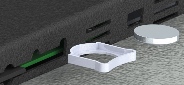
Indice degli argomenti
1    Norme di sicurezza.....................................................................................................................................................20
            1.1 Regolamenti e procedure..................................................................................................................20
            1.2 Linee guida per l’installazione..........................................................................................................20
            1.3 Virus e programmi pericolosi............................................................................................................20
            1.4 Organizzazione delle note di sicurezza.......................................................................................... 21
2    Installazione del dispositivo..................................................................................................................................... 21
            2.1 Spazi per la circolazione dell’aria e la ventilazione..................................................................... 21
3    Alimentazione e messa a terra dello strumento..................................................................................................22
4    Collegamenti elettrici.................................................................................................................................................22
5    Dati tecnici....................................................................................................................................................................22
            5.1 Caratteristiche generali......................................................................................................................22
            5.2 Caratteristiche hardware...................................................................................................................22
            5.3 LCD touch: 4 fili resistivo.....................................................................................................................23
6    Interfacce di comunicazione....................................................................................................................................23
            6.1 CANopen................................................................................................................................................23
                      6.1.a Utilizzo CAN / EXP1 su morsetto M1..................................................................................23
            6.2 RS232......................................................................................................................................................23
                      6.2.a Utilizzo RS232 / COM1 su DB9 (Non disponibile per TD410)........................................23
            6.3 RS485...................................................................................................................................................... 24
                      6.3.a Utilizzo RS485 / COM2 su morsetto M1............................................................................ 24
                      6.3.b Utilizzo RS485 / COM2* MASTER su DB9 (Non disponibile per TD410)..................... 24
                      6.3.c Utilizzo RS485 / COM2 SLAVE su DB9 (Non disponibile per TD410)........................... 24
            6.4 Interfaccia USB..................................................................................................................................... 24
7    Interfaccia Ethernet....................................................................................................................................................25
            7.1 Dati tecnici.............................................................................................................................................25
8    Switch ethernet interno (solo TD810-TD820).......................................................................................................25
9    Batteria..........................................................................................................................................................................25
            9.1 Sostituzione batteria tampone interna..........................................................................................25
            9.2 Dettagli della batteria........................................................................................................................26
10   TdControlPanel............................................................................................................................................................26
     10.a WIN EXPLORER.................................................................................................................................................. 27
     10.b HMI_MOVICON................................................................................................................................................. 27
     10.c PLC LOGICLAB.................................................................................................................................................... 27
     10.d LAN ETH1............................................................................................................................................................ 27
     10.e BACKLIGHT - BUZZER.......................................................................................................................................28
     10.f WINVNC..............................................................................................................................................................28
11   Suite LogicLab..............................................................................................................................................................28
     11.a Cambio lingua...................................................................................................................................................28
     11.b Creazione - caricamento di un progetto.....................................................................................................29
     11.c Collegamento al target...................................................................................................................................29
     11.d Compilazione e scaricamento del codice...................................................................................................30
     11.e La watch window.............................................................................................................................................30
12   Interfacciare Movicon 11 con LogicLab................................................................................................................. 31
     12.a Creazione di un nuovo progetto Movicon................................................................................................. 31
     12.b Configurazione del Driver.............................................................................................................................. 32
     12.c Trasferimento del codice Movicon nel target............................................................................................ 33
13   Simulazione dell’intero progetto SoftPLC + SCADA...........................................................................................34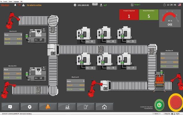
1            Safety guidelines
Programmable logic controllers (PLCs), operating/monitoring devices (industrial PCs, HMI) have
been designed, developed and manufactured for conventional use in industrial environments. They
were not designed, developed and manufactured for any use involving serious risks or hazards that
could lead to death, injury, serious physical damage or loss of any kind without the implementation
of exceptionally stringent safety precautions. In particular, such risks and hazards include the use of
these devices to monitor nuclear reactions in nuclear power plants, their use in flight control or flight
safety systems as well as in the control of mass transportation systems, medical life support systems
or weapons systems.

1.1          Policies and procedures
Electronic devices are never completely failsafe. If the programmable control system, operating/
monitoring device or uninterruptible power supply fails, the user is responsible for ensuring that other
connected devices, e.g. motors, are brought to a secure state.
When using programmable logic controllers or operating/monitoring devices as control systems
together with a soft PLC, safety precautions relevant to industrial control systems must be observed
in accordance with applicable national and international regulations. The same applies for all other
devices connected to the system, such as drives.
All tasks such as the installation, commissioning and servicing of devices are only permitted to be
carried out by qualified personnel. Qualified personnel are those familiar with the transport, mounting,
installation, commissioning and operation of devices who also have the appropriate qualifications
(e.g. IEC 60364). National accident prevention regulations must be observed.
The safety notices, information on connection conditions (type plate and documentation) and limit
values specified in the technical data are to be read carefully before installation and commissioning
and must always be observed.

1.2          Installation guidelines
• These devices are not ready for use upon delivery and must be installed and wired according to the
  specifications in this documentation in order for the EMC limit values to apply.
• Installation must be performed according to this documentation using suitable equipment and tools.
• Devices are only permitted to be installed by qualified personnel without voltage applied. Before
  installation, voltage to the control cabinet must be switched off and prevented from being switched
  on again.
• General safety guidelines and national accident prevention regulations must be observed.
• Electrical installation must be carried out in accordance with applicable guidelines (e.g. line cross
  sections, fuses, protective ground connections).

1.3          Viruses and dangerous programs
This system is subject to potential risk each time data is exchanged or software is installed from a data
medium (e.g. diskette, CD-ROM, USB flash drive, etc.), a network connection or the Internet. The user is
responsible for assessing these dangers, implementing preventive measures such as virus protection
programs, firewalls, etc. and making sure that software is only obtained from trusted sources.

1.4          Organization of safety notices
Safety notices in this manual are organized as follows:
Safety notice   Description
Danger!         Disregarding these safety guidelines and notices can be life-threatening.
                Disregarding these safety guidelines and notices can result in severe injury or
Warning!
                substantial damage to property.
                Disregarding these safety guidelines and notices can result in injury or damage to
Caution!
                property.
Information! This information is important for preventing errors.
                                                                                      User manual - HMI Series - 5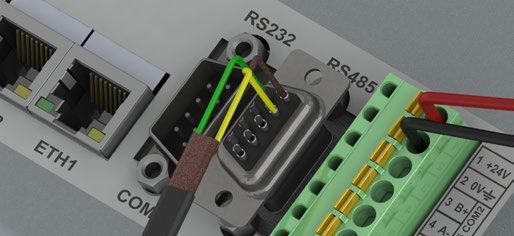
2                  Device installation
The device panel is installed in the cutout using provided plastic hooks. The number of provided
plastic hooks depends on the panel. The thickness of the wall or cabinet plate must be between 1 mm
and 5 mm. An ISO 7045 (ex UNI 7687 DIN 7985A) Phillips screwdriver is needed to tighten and loosen
the screws on the retaining clips. The maximum tightening torque for the retaining clips is 0,5 Nm.
Devices must be installed on a flat, clean and burr-free surface; uneven areas can cause damage to
the display when the screws are tightened or the intrusion of dust and water. (as per figures 1 and 2)
 Cut-out                            Fig. 1                           Fig. 2

                L (± 0,5 mm)

            H (± 0,5 mm)

                                    TD410            TD710            TD810             TD820
External dimensions (mm)            140 x 100 x 29   204 x 160 x 35   274 x 216 x 35    317 x 256 x 35
Cut-out (mm)                        132 x 90         181 x 144        259 x 202         302 x 242

2.1                Spacing for air circulation and ventilation
In order to guarantee sufficient air circulation, allow 5cm of empty space above, below, to the side
and behind the device. No other ventilation system is required. The HMI device is self-ventilated and
approved for inclined mounting at angles up to ±35°in stationary cabinets.

    Information! If additional space is needed to operate or maintain the device, this must be taken into
    consideration during installation.

    Caution! The spacing specifications for air circulation are based on the worst-case scenario for
    operation at the maximum specified ambient temperature. The maximum specified ambient
    temperature must not be exceeded!

    Caution! An inclined installation reduces the convection by the HMI device and therefore the
    maximum permissible ambient temperature for operation.

3                  Power supply and grounding
                                    Danger! This device is only permitted to by supplied by a SELV /
                                    PELV (class 2) power supply or with safety extra-low voltage (SELV)
                                    in accordance with EN 60950.

                                  Connect a 24VDC 1,0A (min.) power supply, as showed into the figure.
                                  Connect the device grounding with a conductor of 18AWG (2,5mmq)
                                  minimum section. For the whole series it is suggested to use a 24
                                  VDC 1,0A 24VA power supply (Pixsys code 2700.10.008).
                                  Use Copper, Copper-Clad Aluminium or Aluminium conductors wire
                                  for all electric connection.

                                    Caution! 24VDC power supply line must be protected by a 1,0A fuse.
                                    Caution! Functional ground must be kept as short as possible and
                                    connected to the largest possible wire cross section at the central
                                    grounding point (e.g. the control cabinet or system).
6 - HMI Series - User manual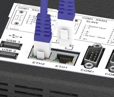
4                   Wiring connections
This device has been designed and manufactured in conformity to Low Voltage Directive 2006/95/EC,
2014/35/EU (LVD) and EMC Directive 2004/108/EC, 2014/30/EU (EMC). For installation into industrial
environments please observe following safety guidelines:
• Separate control lines form power wires;
• Avoid proximity of remote control switches, electromagnetic contactors, powerful engines and use
   specific filters;
• Avoid proximity of power groups, especially those with phase control;
• It is strongly recommended to install adequate mains filter on power supply of the machine where
   the controller is installed, particularly if supplied 230 VAC. The controller is designed and conceived
   to be incorporated into other machines, therefore CE marking on the controller does not exempt
   the manufacturer of machines from safety and conformity requirements applying to the machine
   itself.

5                   Technical data
5.1                 Main features
                                                TD410           TD710            TD810          TD820
Power supply voltage                            12 ÷ 24 VDC ± 10%
Consumption (typical
                                                7,5 VA          13 VA            16 W           15 W
use with 2 USB devices)
Temperature range                               0..50°C
Humidity range                                  10..90% (without condensation)

5.2                 Hardware features
CPU                                             ARM® CORTEX™ - A8 @1.0GHz
RAM                                             512 MB DDR3
eMMC                                            4GB

5.3                 Touch LCD: 4 wires resistive
                                                TD410           TD710            TD810           TD820
                                                4.3” TFT        7” TFT           10” TFT         12” TFT
Resolution
                                                480 x 272       800 x 480        800 x 600       1280 x 800
Colors                                          65K (16 bit)    65K (16 bit)     65K (16 bit)    65K (16 bit)
Back-lighting                                   LED 400 cd/m2 LED 280 cd/m2      LED 320 cd/m2 LED 220 cd/m2
Back-lighting duration*                         50000 h Typ @ 25°C**             30000 h Typ @ 25°C**
Lifetime**                                      17                               10
*   Brightness reduction to the 80% of default setting

** Functioning years per 8 hours / day

6                   Communication interfaces
TD410             TD710*** - TD810 - TD820

*** ETH2 not available on this model.

                                                                                               User manual - HMI Series - 7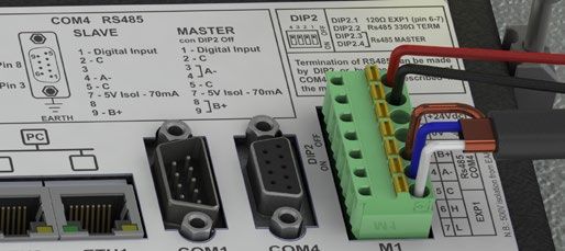
6.1                 CANopen
6.1.a               Using CAN / EXP1 on terminal M1

                                                                                   DIP2

                                                                                                     OFF
                                                                                                            EXP1/CAN with termination resistor 120Ω
                                                                                                            EXP1/CAN con terminazione 120Ω

                                                                                                     ON
                                                                              PIN5: GND (brown)
                                                                              PIN6: CANH (blue)
                                                                              PIN7: CANL (white)

6.2                 RS232
6.2.a               Using RS232 / COM1 on DB9 (No available for TD410)

                                                                              RS232 connection with RTS / CTS:
Standard RS232 connection:                                                    PIN2: RX (green)
PIN2: RX (green)                                                              PIN3: TX (blue)
PIN3: TX (blue)                                                               PIN5: GND (brown)
PIN5: GND (brown)                                                             PIN7: RTS (white)
                                                                              PIN8: CTS (yellow)

6.3                 RS485
6.3.a               Using RS485 / COM2 on terminal M1
                                                                                   DIP2
                                                                                                            RS485 MASTER:
                                                                                                      OFF

                                                                                                            Termination 330Ω Polarization 470Ω
                                                                                                            Terminatore 330Ω Polarizzatore 470Ω
                                                                                                      ON

                                                                                                            RS485 MASTER:
                                                                                                      OFF

                                                                                                            Polarization only 470Ω
                                                                                                            Solo polarizzatore 470Ω
                                                                                                      ON
                                                                                                      OFF

                                                                                                            RS485 SLAVE
                                                                                                      ON

                                                                              PIN3: B+ (green)
                                                                              PIN4: A- (yellow)
                                                                              PIN5: GND (brown)

6.3.b               Using RS485 / COM2* MASTER on DB9 (No available for TD410)
                                                                                DIP2
                                                                                       ON OFF

                                                                                                DIP2 2,3,4 to off

                                                                                                            COM2 RS485
                                                                                Pin 7 : 5Vi                               MASTER
                                                                                                       9       5          1 - Input
                                                                                           470 Ω                          2-C
                                                                                            Pin 8                         3 A-
                                                                                           330 Ω                          4
                                                                                            Pin 3 6            1          5-C
                                                                                           470 Ω                          7 - 5V
                                                                                                                          8
                                                                                                                              B+
                                                                                Pin 5 : C                  EARTH          9
                                                                                Note: 5V Is isolated an can supply 70mA max

*   Using the DB9 connector it is possible to introduce termination resistances using DIP2 as for terminal M1 or short-circuiting terminals 3-4 e 8-9, as showed
    in the figure.

8 - HMI Series - User manual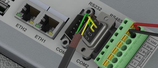
6.3.c       Using RS485 / COM2 SLAVE on DB9 (No available for TD410)
                                                   DIP2

                                                          ON OFF
                                                                   DIP2 2,3,4 to off

                                                                              COM2 RS485
                                                   Pin 7 : 5Vi                         SLAVE
                                                                          9      5 1 - Input
                                                              470 Ω    2-C
                                                               Pin 8   3-
                                                              330 Ω    4 - A-
                                                        Pin 3 6      1 5-C
                                                       470 Ω           7 - 5V
                                                                       8-
                                                   Pin 5 : C    EARTH  9 - B+
                                                   Note: 5V Is isolated an can supply 70mA max

6.4         USB interfaces
The HMI comes equipped with a USB 2.0 (Universal Serial Bus) host controller with multiple USB
interfaces accessible externally for the user.

  Warning! Peripheral USB devices can be connected to the USB interfaces on this device. Due to the
  large number of USB devices available on the market, Pixsys cannot guarantee their performance.

  Caution! Because this interface is designed according to general PC specifications, extreme care
  should be exercised with regard to EMC, cable routing, etc.

Type                         USB 2.0
Design                       Type A
Transfer rate                Low speed (1.5 Mbit/s), Full speed (12 Mbit/s), High speed (480 Mbit/s)
Current-carrying capacity    Max. 0,8 A (total of all USB ports)
Cable length                 Max. 3 m (without hub)

7           Ethernet interface
7.1         Technical data
This Ethernet controller is connected to external devices via the system unit.
Ethernet 1 interface (ETH1) TD410 - TD710                         TD810 - TD820
Number of ports             1                                     2
Controller                  LAN8710A
Cabling S/STP               (Cat 5e)
                                                                  10/100 Mbit/s ETH1-ETH2 to CPU Link
Transfer rate               10/100 Mbit/s
                                                                  10/100/1000 Mbit/s ETH1-ETH2 link
Cable length                Max. 100 m (min. Cat 5e)
LED
                                                                  On = Gigabit connection
Green                       Link
                                                                  Off = 10/100 Mbit connection
                                                                  On =Link
Yellow                      10/100 Mbit Activity
                                                                  Blink = Activity (data transfer)

                                                                                                 User manual - HMI Series - 9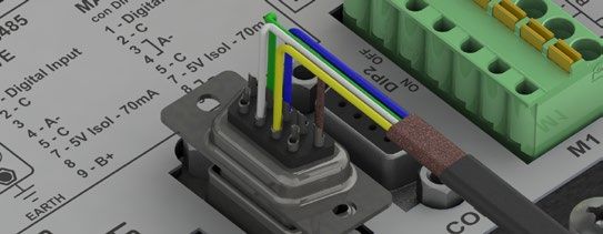
8                  Internal ethernet Switch (only TD810-TD820)
                                       Two Ethernet 10/100/1000 Mbit ports on the rear side of the
                                       operator panel are available. ETH1 and ETH2 are internally
                                       connected to CPU through a Gigabit switch.
                                       Thanks to dual port it is possible to make daisy-chain of more
                                       devices without using external ethernet switches.
                                       Using VLAN system option, each port can be used as separated
                                       network interface. See TDControl user manual for more details.
                                       For TD410 and TD710 only one Ethernet port is available.
                                                      LAPTOP

9                  Battery
9.1                Internal battery replacement
BIOS and clock store data also in case of power failure thanks to a CR2032 battery placed on the side.
To replace the battery it is necessary to remove the protection and pull out the extraction box using
a blade screwdriver.

9.2                Battery detail
Classification                   Lithium Coin
Chemical System                  Lithium / Manganese Dioxide (Li/MnO2)
Nominal Voltage                  3.0 Volts
Typical Capacity                 235 mAh (to 2.0 volts)
Typical (Li) Content             0.109 grams (0.0038 oz.)
Energy Density                   198 milliwatt hr/g, 653 milliwatt hr/cc
Operating Temp                   -30C to 60C

    Warning! CR2032 is a “Lithium Coin” battery

    Danger! KEEP OUT OF REACH OF CHILDREN. Swallowing may lead to serious injury or death in as little
    as 2 hours due to chemical burns and potential perforation of the esophagus. To prevent children
    from removing batteries, battery compartments is designed to be opened with a screwdriver and is
    protected by a security label.

    Warning! It is suggested to replace the battery every 3 years. When the battery is removed, an
    internal dedicated device allows replacement without data loss if operation is completed within 1
    hour since battery removal.

10 - HMI Series - User manual
10 TdControlPanel
At switch-on a project starts allowing to verify the machine
general status, date/system hour, related IP address, SoftPLC
execution in background.
Using a VNC client you can view from your PC what is displayed on the PLC / HMI. Starting a browser
with active Java service it is possibile to test if the device Webserver function is active. For this function
it is necessary to use Internet Explorer.
Press “Td Control Panel,” to access the device control
panel and verify/configure all the services and projects to
be launched at starting. It is possible also to configure the
standby time for the backlighting switch off and the buzzer
at display pressure.
The following paragraphs describe each function of the TdControlPanel windows.
NB: Pictures show device standard configuration.
10.a WIN EXPLORER
From this window it is possible to choose a set of options to
start Windows CE and execute TDControlPanel.
• The first option starts Windows CE with desktop.
• The second option allows TDControlPanel starting if ,
during the switch on , the key “Stop” is keep pressed .
• Enabling the third option it is possible to set a protection
password to avoid that unauthorized users, keeping
pressed “STOP” , access TDControlPanel settings..
“START WINDOWS DESKTOP” allows to start “Explorer.exe” to access Windows CE desktop.
10.b HMI_MOVICON
From this window it is possible to select which Movicon 11
services/programs execute automatically at starting.
The functions of the Movicon scada are available in all
HMI and in “WEB” version PL500 (PL500-335-1AD-WEB)
“START” activates manually the Movicon project (and the file upload service)
User manual - HMI Series - 1110.c PLC LOGICLAB
From this window it is possible to enable/disable the SoftPLC
execution at starting. Selecting “RUN console DEBUG”, during
the SoftPLC execution, the Debug window will be filled with
real-time system events to verify possible anomalies.
NB: this function requires many device resources. It is
suggested to keep it active only if there are problems during
the software development. Disable this function at the end
of the development phase.
“START” activates manually the SoftPLC project (and any debug window).
10.d LAN ETH1
From this window it is possible to modify the device net
configuration parameters. Any modification will require a
restart to be applied.
NB: to transfer the SoftPLC program and Movicon on the
device, it must have a fixed address. It is not possible to
operate in DHCP.
The HMI default IP address is 192.168.0.100
The PL500 default IP address is 192.168.0.99
10.e BACKLIGHT - BUZZER
From this window it is possible to configure backlighting
and buzzer parameters.
Enabling “Always ON” the backlighting keeps always active.
Otherwise, enter time value in seconds on “Backlight ON for..
(sec)” to enable the switching off or the lamp attenuation.
The first two fields allows to select the lamp brightness
percentage (100% = ON, 0%=OFF) during standard
operation or standby.
“Buzzer frequency” allows to select the buzzer tone frequency
(an higher frequency corresponds to a more acute tone).
Select “Buzzer OFF” to deactivate the buzzer at touch.
“TEST” keys allow to test selected parameters before saving
the configuration.
10.f WINVNC
From this window it is possible to enable/disable the VNC
remote Desktop service. Press“START VNC” to activate
manually this service. Press “START VNC_CONFIG” to access
VNC configuration window and set the authentication
system or modify access password. NB. Parameter modifica-
tion is recommended to expert users, incorrect parameters
modification will cause remote desktop service malfunctio-
ning. Default password to access remote Desktop through
VNC is “1234”.
12 - HMI Series - User manual11 LogicLab Suite
LogicLab Suite is the Pixsys development environment for the programming of PLC series, PL500 and
all Operator panels / PanelPC.
The suite is available for free download within “download area” of the website pixsys.net, no activation
code is required (only registration). Supported by all 32/64bit Windows versions, starting from
Windows XP SP3. Available both in English and Italian version. Once downloaded the setup file on
the computer, start the installation and follow the standard procedure. The program can be activated
through the icon ”LogicLab” (on desktop) or from the menu “Start” > “PixsysSuite” > “LogicLab”.
11.a Language modification
To modify the visualization language it is
necessary to open options window form the
menu “File” > “Options”, go to “Language”, select
“ITA - italiano” and press “Select”. Confirm with
“OK” , close and re-open LogicLab to enable the
modification.
11.b Create - load a project
Open an exsisting project:
• With LogicLab opened, click on “Open
project” or select one of the last projects form
the list.
• With LogicLab closed, enter on the project
folder and select (double click) the chosen
file (icon and extension “.plcprj”).
Create a new project:
Press “New project”.
Enter the name of the new project and select
the folder where the project files will be stored.
Finally, select the device to be programmed.
Attention: selecting “respect capital/lowercase letters”, a variable which contains a capital letter
will be understood as different from another with the same name but with this letter lowercase. It
is recommended to keep this selection disabled, to avoid any confusion durign the drafting of the
program code.
User manual - HMI Series - 1311.c Connection to target
Here below please find the necessary requirements for the correct connection between target (device
to be programmed) and the development environment on PC (LogicLab).
Target requirements:
• device ON and started
• configured with static IP address compatible with the network where there is the PC to which it will
connect. By default, the IP address of the HMI is 192.168.0.100, for PL500 is 192.168.0.99, so the PC
must have the same network and class (in this case 192.168.0.XXX) but different physical address
(the last 3 digits of the IP address, with a number between 1 and 255, different from 100). If it is
necessary to modify the IP address of the terminal, refer to the TD Control Panel configuration,
section “LAN ETH1” on par. 10.d.
• connection with net cable (direct or cross) directly to PC or through a net switch
• SoftPLC in execution (refer to TD Control Panel configuration, section “PLC LOGICLAB” on par. 10.c).
PC requirements:
• IP address compatible with the network where it is located and with the IP address configured on
the target (see previous points)
• antivirus/firewall which allows the connection to network devices (normally already correctly
configured)
• LogicLab configured for the connection to the target to be programmed: menu “On Line” > “Select
communication” , on the window that opens press “Properties” and than enter the target IP on “IP
Address” , keeping all the rest unaltered. In case of very slow networks or of a network configuration
with different switches, it is possibile to increase the “Timeout” value (expressed in mS).
The image represents default configuration
Confirm all windows pressing “OK” and save through or from the menu “file” > “SaveProject”.
To verify the correct LogicLab and Target configurations, it is possible to make the connection pressing
or form the menu “On Line” > “Connect”. If the connection is correctly done, the status bar at the
lower right side will visualize “CONNECTED” and “NO CODE” (to indicate that the target is connected
and has no code in it) or “DIFF CODE” (to indicate that the code which is being visualized does not
correspond to those who lies in the target).
14 - HMI Series - User manual11.d Compiling and downloading the code
Once entered the project code it is necessary to verify eventual errors pressing F7, clicking on icon
or from the menu “Project” > “Fill”.
If the compilation is correctly done it is possible to transfer the program to the target pressing F5,
through icon or from the menu “On Line” > “Code transferring”.
The status bar will show “CONNECTED” and “SOURCE OK” indicating that the program running on the
target corresponds to that which is visualized on PC.
11.e Watch window
If the program running on the target corresponds to that which is being visualized on PC, the status
bar will show “CONNECTED” and “SOURCE OK” and it is possible to use the window “Watch” to verify
real-time the status of the variables used in the project. To enable the window “Watch”, press CTRL+T
or use “View” > “View tool window” > “Watch”. To add a variable to the window “Watch”, just drag it inside
or press the icon and select it manually.
From now on, the window “Watch” will visualize
the value of the inserted variable, in real time.
Through it is possible to save, load and add an exsisting watch-list to the list of variables.
To change the visualization format, it is
necessary to select the variable and press
. On the window that opens, select the chosen
format and confirm pressing “OK”.
User manual - HMI Series - 1512 Interfacing Movicon 11 with LogicLab
NB: Movicon 11.5 or greater.
To execute only once:
On PC, copy files “Drivers.xml” and “Pixsys.dll” in C:\Program Files (x86)\Progea\Movicon11.5\Drivers
overwriting those already present.
Do the same procedure also if a Panel PC (TD750-TD850-TD900-TD910-TD920) is used.
Note:
With this procedure all PLC system variables and variables created and used in the PLC are imported.
The creation and the updating of the PLC variables list is done only if the LogicLab program is
compiled without errors and downloaded on the target.
12.a Creating a new Movicon project
Start the software and choose the platform “Windows® X86 / X64” for Panel-PC or “Windows® CE
Platform” for HMI and for “WEB” version of PL500. If the new Movicon project is being created following
the Wizard, at the end it will visualize the driver configuration window, switch to the section “Driver
Configuration” to par. 12.b. If the driver is being installed manually, proceed as follow:
Add the communication driver with a right click
on “Real time DB” and then “new communication
driver”.
Select “Pixsys” from the manufacturer menu and
then “SoftPLC Pixsys”.
Confirm with “OK” and double click on the driver
just created to open the configuration window.
12.b Driver configuration
Select “Station” and add a new station pressing
“ADD”.
16 - HMI Series - User manual1. Enter source path of the LogicLab project located on the PC used for development. This allows to
import variables, execute Movicon in preview mode on own PC, including communication with
SoftPLC, and perform complete test. Next step is to indicate IP address of the target HMI/PC (only
after completing development it will be necessary to enter localhost address 127.0.0.1 to enable
communication of Movicon project with the softPLC of the panel itself.
2. This field is self-compiling after entering path as described on previous point. If using an HMI/
PL500, do not modify the self-compiling field; if using a Panel PC (TD750, TD850 etc…) enter the
path used for download of the LogicLab project (default D:\LLExec\ NameMyProjectLogicLab.sym.
xml).
3. If Movicon project will be executed on the HMI/PC where the softPLC is also installed, then the IP
address will be 127.0.0.1. If it will be executed on a different HMI/PC, then enter the IP address of the
softPLC.
4. From the section “General” assign a name to the station, ex. “PLC”.
Press OK to save settings and exit.
Now it is possible to import the LogicLab
project variabiles on Movicon.
Right click on “SoftPLC Pixsys” and select “Import
PLC database”.
Press “Read from PLC project”, the list of all
available variables will be provided.
Select variables to be imported and press
“Import”.
NB: If importing an array variable, it will be visualized as a structure carrying the array name.
Single array members will be accessible individually with following syntax NameMyArray:NameMyArray
_X where X is the array index (starting from 0).
Now variables are available on the Movicon project. If it is necessary to import new variables (to modify
LogicLab project), repeat only the reading and import variables procedure.
User manual - HMI Series - 1712.c Downloading the Movicon code to the target
To downlaod the Movicon Project, use the icon:
1. Select the protocol used to transfer the code:
TCP
2. Insert the target IP address (default for HMI/
PLC: 192.168.0.100).
3. If using an HMI/PLC leave the field blank,
if using a Panel-PC insert user (or the user
name that is logged on the Panel-PC target).
4. If using an HMI/PLC leave the field blank, if
using a Panel-PC insert 123456
5. If using an HMI/PLC insert \NandFlash\
MyMoviconProjectName\, if using a Panel-PC
insert D:\MyMoviconProjectName\. In this way
Movicon will create a folder named MyMovi-
conProjectName and it will download all the
project files into it.
6. Press “Upload Project!“ to download the
project files to the target (press “Yes to All“
if a project was already downloaded to
overwrite the old files).
NB: if you need to trasfer different projects/versions to the target, you can change the destination
folder (you must mantain the first part of the address \NandFlash\).
Using the TdControlPanel is possible to select which Movicon 11 project will be executed automatically
at starting (see paragraph 10.b).
7. Once the download is completed, press “Start Deviec Project“ to launch the execution of the project
in the target (the project in execution will be closed and the new one will be executed).
13 Simulation of the whole project SoftPLC + SCADA
From LogicLab, launch the simulator through the icon or from menu “Debug” > “Simulation mode”.
On the window which appears, create a new working area indicating the name and the destination
folder (by default it is selected the folder where the project risiede).
At this point, the simulator will be activated and connected (status window shows “CONNECTED”) but
without the code (status window shows “NO CODE”), transfer the code pressing F5, through the icon
or from the menu “Online” > “Online download code”.
Verify that the status bar visualize“CONNECTED” and “SOURCE OK”. If “NO CODE is still visualized, restart
the simulator pressing or from the menu “On-line” > “Target reboot”.
On Movicon, entering the Pixsys driver configurator and configure as follows:
1. Enter the folder where the simulator is
operating, set as filter “All files (*.*) and
select the file NameMyProjectLogicLab.
sym.simul. Pay attention to the file
exstension, into the project folder there
are many files with the same name but
different extension.
2. Enter the folder where the LogicLab
project resides and select the file Na-
meMyProjectLogicLab.sym.xml
3. Select the localhost address: 127.0.0.1
18 - HMI Series - User manualAt this point, to start the simulation of the graphic interface connected to the simulator (which is
already executing the code previously downloaded), press Alt+F12, the icon or from the menu “File”
> “Start Project”.
To end the simulation, press Alt+F12 or the icon on the bar which appears on the upper side.
Warranty terms
Pixsys srl warrants its electronic devices for 12 months from Invoice date. Pixsys liability shall be limited
to repairing (or replacing at its option) any defective product which is returned with RMA (Return
Material Authorization) priorly obtained on Pixsys website and to be clearly marked on documents.
Pixsys shall not be responsible for accident, neglect, misuse, damage to objects or people caused
using the devices outside their specifications or outside any published performance data, including
unauthorized and unqualified repairing or failure to provide proper environmental conditions. In no
event shall Pixsys liability exceed the purchase price of the product(s).
Warranty does not cover any damage arising from post-sale installation of software applications and
specifically any damage caused by malware. Technical assistance by Pixsys which should be required
to restore OS will be subject to assistance fee prevailing at time of request.
Notes / Updates
User manual - HMI Series - 191 Norme di sicurezza Le indicazioni di questo manuale sono riferite a prodotti Pixsys quali i dispositivi logici programmabili (PLC) e i dispositivi di controllo e monitoraggio (PC industriali, HMI) da ora in poi identificati semplicemente con il termine “Il dispositivo” o “i dispositivi”. I dispositivi realizzati e commercializzati da Pixsys sono progettati, sviluppati e realizzati per un uso convenzionale in ambienti industriali. Non sono stati progettati, sviluppati e realizzati per qualsiasi altro uso che possa comportare gravi rischi o pericoli quali decesso, lesioni, gravi danni fisici senza che siano adottati rigorosi sistemi di sicurezza indipendenti dal dispositivo. In particolare, tali rischi e pericoli includono l’uso di questi dispositivi per monitorare le reazioni nucleari nelle centrali, il loro uso nei sistemi di controllo o sicurezza del volo, nonché nel controllo di sistemi di trasporto di massa, supporto a sistemi salvavita medicali o sistemi d’armamento. 1.1 Regolamenti e procedure I dispositivi elettronici non sono mai completamente sicuri. Se il dispositivo viene meno al suo funzionamento, l’utente è responsabile di garantire che altri dispositivi connessi, ad es. motori, siano portati in una condizione di sicurezza. Le precauzioni di sicurezza inerenti i sistemi di controllo industriale devono essere adottate in conformità alle normative nazionali e internazionali applicabili quando si utilizzano i dispositivi come sistemi di controllo insieme a Soft-PLC. Lo stesso vale per tutti gli altri dispositivi collegati al sistema. Tutte le operazioni come l’installazione, la messa in servizio e la manutenzione dei dispositivi devono essere eseguite solo da personale qualificato. Il personale qualificato deve avere familiarità con il trasporto, montaggio, installazione, messa in servizio e funzionamento dei dispositivi ed avere le previste qualifiche ad operare (ad esempio IEC 60364). È necessario osservare le norme nazionali sulla prevenzione degli incidenti. Le avvertenze di sicurezza, le informazioni sulle condizioni di collegamento (etichette e documenta- zione) e i valori limite specificati nei dati tecnici devono essere letti attentamente prima dell’installa- zione e della messa in servizio e devono essere sempre osservati. 1.2 Linee guida per l’installazione • Questi dispositivi non sono pronti per l’uso al momento della consegna, devono essere installati e cablati secondo le indicazioni specifiche di questa documentazione al fine di rispettarne i limiti EMC e gli standard di sicurezza. • L’installazione deve essere eseguita secondo questa documentazione utilizzando attrezzature e strumenti adeguati. • I dispositivi devono essere installati solo da personale qualificato senza tensione applicata. Prima dell’installazione, la tensione all’armadio elettrico deve essere spenta e ne deve essere impedita l’accensione per tutto il tempo dell’intervento. • Devono essere osservate le linee guida generali sulla sicurezza e le norme nazionali sulla prevenzione degli incidenti. • L’installazione elettrica deve essere eseguita in conformità alle linee guida applicabili (ad esempio sezioni trasversali della linea, fusibili, collegamenti di terra protettivi). 1.3 Virus e programmi pericolosi Questo sistema è soggetto a potenziali rischi ogni volta che i dati vengono scambiati o il software viene installato da un supporto dati (ad esempio CD-ROM o flash-disk USB), una connessione di rete o Internet. L’utente è responsabile della valutazione di questi pericoli, implementando misure preventive come programmi di protezione antivirus, firewall, ecc. e assicurandosi che il software sia ottenuto solo da fonti attendibili. 20 - HMI Series - Manuale d’uso
1.4           Organizzazione delle note di sicurezza
Le note sulla sicurezza in questo manuale sono organizzate come segue:
Note di sicurezza Descrizione
                  La mancata osservanza di queste linee guida e avvisi di sicurezza può essere poten-
Danger!
                  zialmente mortale.
                  La mancata osservanza di queste linee guida e avvisi di sicurezza può comportare
Warning!
                  lesioni gravi o danni sostanziali alla proprietà.
                  La mancata osservanza di queste linee guida e avvisi di sicurezza può provocare
Caution!
                  lesioni o danni alle cose.
Information! Tali informazioni sono importanti per prevenire errori.

2             Installazione del dispositivo
Il pannello del dispositivo è installato nel foro sul pannello macchina utilizzando i ganci in plastica
forniti seguendo le indicazioni di figure 1 e 2.
Il numero di ganci in plastica forniti dipende dal pannello da installare. Lo spessore della parete o della
piastra da forare per installare il dispositivo deve essere compresa tra 1 mm e 5 mm. È necessario un
cacciavite Phillips ISO 7045 (ex UNI 7687 DIN 7985A) per serrare o allentare le viti dei ganci di fissaggio.
La coppia di serraggio massima per i ganci di fissaggio è di 0,5 Nm. I dispositivi devono essere installati
su una superficie piana, pulita e senza sbavature; aree irregolari possono danneggiare il display
quando le viti sono serrate o permettere l’intrusione di polvere e acqua.
 Dima foratura                       Fig. 1                             Fig. 2

            L (± 0,5 mm)

         H (± 0,5 mm)

                                    TD410             TD710             TD810              TD820
Dimensioni esterne (mm)             140 x 100 x 29    204 x 160 x 35    274 x 216 x 35     317 x 256 x 35
Dima di foratura (mm)               132 x 90          181 x 144         259 x 202          302 x 242

2.1           Spazi per la circolazione dell’aria e la ventilazione
Per garantire una circolazione sufficiente dell’aria lasciare 5 cm di spazio vuoto sopra, sotto, di lato
e dietro il dispositivo. Nessuna altra ventilazione del sistema è richiesta. Il pannello operatore è
autoventilato e omologato per il montaggio inclinato con angoli fino a ± 35° in armadi fissi.

    Information! Se è necessario spazio aggiuntivo per operare o mantenere il dispositivo, questo deve
    essere preso in considerazione durante l’installazione.
    Caution! Le specifiche di spazio per la circolazione dell’aria si basano sullo scenario peggiore di
    funzionamento. La temperatura ambiente massima specificata non deve essere superata!
    Caution! Un’installazione inclinata riduce la convezione del pannello operatore e quindi la
    temperatura ambiente massima consentita per operazione che dovrà essere valutata assieme al
    supporto tecnico Pixsys.

                                                                                      Manuale d’uso - HMI Series - 21
3 Alimentazione e messa a terra dello strumento
Danger! Questo dispositivo può essere alimentato solo da una
sorgente di alimentazione SELV / PELV (classe 2) o in classe di
sicurezza per bassissima tensione (SELV) secondo EN 60950.
Collegare una sorgente di alimentazione a 24VDC 1,0A (min.) come
nella figura accanto. Collegare la presa di TERRA dello strumento
con un conduttore di sezione minima 18AWG (2,5mmq). Per tutta la
gamma di strumenti si consiglia l’utilizzo di un alimentatore dedicato
da almeno 24 VDC 1,0A 24VA, vedere codice 2700.10.008.
Utilizzare fili in rame, alluminio rivestito in rame o alluminio per tutti
i collegamenti elettrici.
Caution! La linea di alimentazione 24 VDC deve essere protetta da
un fusibile da 2,5 A.
Caution! I collegamenti di massa devono essere il più corti possibili
ed eseguiti con filo con la sezione massima possibile verso il punto
centrale di messa a terra (ad esempio l’armadio o il sistema di
controllo).
4 Collegamenti elettrici
Il device è stato progettato e costruito in conformità alle Direttive Bassa Tensione 2006/95/CE, 2014/35/
UE (LVD) e Compatibilità elettromagnetica 2004/108/CE e 2014/30/UE (EMC). Per l’installazione in
ambienti industriali è buona norma seguire la seguenti precauzioni:
• Distinguere la linea di alimentazioni da quelle di potenza.
• Evitare la vicinanza di gruppi di teleruttori, contattori elettromagnetici, motori di grossa potenza e
comunque usare appositi filtri.
• Evitare la vicinanza di gruppi di potenza, in particolare se a controllo di fase.
• Si raccomanda l’impiego di filtri di rete sull’alimentazione della macchina in cui lo strumento
verrà installato, in particolare nel caso di alimentazione 230 VAC. Si evidenzia che il regolatore è
concepito per essere assemblato ad altre macchine e dunque la marcatura CE del regolatore non
esime il costruttore dell’impianto dagli obblighi di sicurezza e conformità previsti per la macchina
nel suo complesso.
5 Dati tecnici
5.1 Caratteristiche generali
TD410 TD710 TD810 TD820
Tensione alimentazione 12 ÷ 24 VDC ± 10%
Consumo (utilizzo tipico con
7,5 VA 13 VA 16 W 15 W
2 device USB)
Range temperatura 0..50°C
Range umidità 10..90% (senza condensa)
5.2 Caratteristiche hardware
CPU ARM® CORTEX™ - A8 @1.0GHz
RAM 512 MB DDR3
eMMC 4GB
22 - HMI Series - Manuale d’uso5.3 LCD touch: 4 fili resistivo
TD410 TD710 TD810 TD820
4.3” TFT 7” TFT 10” TFT 12” TFT
Risoluzione
480 x 272 800 x 480 800 x 600 1280 x 800
Colori 65K (16 bit) 65K (16 bit) 65K (16 bit) 65K (16 bit)
Retroilluminazione LED 400 cd/m2 LED 280 cd/m2 LED 320 cd/m2 LED 220 cd/m2
Durata retroilluminazione* 50000 h Typ @ 25°C** 30000 h Typ @ 25°C**
Lifetime** 17 10
* Riduzione luminosità all’80% del dato di fabbrica
** Anni di funzionamento per 8 ore / giorno
6 Interfacce di comunicazione
TD410 TD710*** - TD810*** - TD820
*** ETH2 non disponibile su questi modelli.
6.1 CANopen
6.1.a Utilizzo CAN / EXP1 su morsetto M1
DIP2
OFF
EXP1/CAN with termination resistor 120Ω
EXP1/CAN con terminazione 120Ω
ON
PIN5: GND (marrone)
PIN6: CANH (blu)
PIN7: CANL (bianco)
6.2 RS232
6.2.a Utilizzo RS232 / COM1 su DB9 (Non disponibile per TD410)
Connessione RS232 con RTS / CTS:
Connessione RS232 base: PIN2: RX (verde)
PIN2: RX (verde) PIN3: TX (blu)
PIN3: TX (blu) PIN5: GND (marrone)
PIN5: GND (marrone) PIN7: RTS (bianco)
PIN8: CTS (giallo)
Manuale d’uso - HMI Series - 236.3 RS485
6.3.a Utilizzo RS485 / COM2 su morsetto M1
DIP2
RS485 MASTER:
OFF
Termination 330Ω Polarization 470Ω
Terminatore 330Ω Polarizzatore 470Ω
ON
RS485 MASTER:
OFF
Polarization only 470Ω
Solo polarizzatore 470Ω
ON
OFF
RS485 SLAVE
ON
PIN3: B+ (verde)
PIN4: A- (giallo)
PIN5: GND (marrone)
6.3.b Utilizzo RS485 / COM2* MASTER su DB9 (Non disponibile per TD410)
DIP2
ON OFF
DIP2 2,3,4 to off
COM2 RS485
Pin 7 : 5Vi MASTER
9 5 1 - Input
470 Ω 2-C
Pin 8 3 A-
330 Ω 4
Pin 3 6 1 5-C
470 Ω 7 - 5V
8
B+
Pin 5 : C EARTH 9
Note: 5V Is isolated an can supply 70mA max
* Utilizzando il connettore DB9 si possono inserire le resistenze di terminazione utilizzando DIP2 come per il morsetto M1 oppure ponticellando, come visibile
in figura, i contatti 3-4 e 8-9.
6.3.c Utilizzo RS485 / COM2 SLAVE su DB9 (Non disponibile per TD410)
DIP2
ON OFF
DIP2 2,3,4 to off
COM2 RS485
Pin 7 : 5Vi SLAVE
9 5 1 - Input
470 Ω 2-C
Pin 8 3-
330 Ω 4 - A-
Pin 3 6 1 5-C
470 Ω 7 - 5V
8-
Pin 5 : C EARTH 9 - B+
Note: 5V Is isolated an can supply 70mA max
6.4 Interfaccia USB
L’HMI è dotato di un controller host USB 2.0 (Universal Serial Bus) con più interfacce USB, una anteriore
e due posteriori accessibili esternamente dall’utente.
Warning! Differenti dispositivi USB possono essere collegati alle interfacce USB su questo dispositivo.
A causa dell’elevato numero di dispositivi USB disponibili sul mercato, Pixsys non può garantire le
loro performance.
Caution! Poiché questa interfaccia è progettata in base a specifiche generali del settore PC, è
necessario prestare la massima attenzione per quanto riguarda EMC, cablaggi, ecc.
Tipo USB 2.0
Tipologia del connettore Type A
Transfer rate Low speed (1.5 Mbit/s), Full speed (12 Mbit/s), High speed (480 Mbit/s)
Massima corrente erogabile Max. 0,8 A (totale di tutte e 3 le porte USB)
Lunghezza cavo Max. 3 m (senza hub)
24 - HMI Series - Manuale d’usoYou can also read