WF-D190 - USER MANUAL MANUALE utente - DIGITAL WIRELESS MICROPHONE SYSTEMS - Strumenti Musicali
←
→
Page content transcription
If your browser does not render page correctly, please read the page content below
WF-D190
       DIGITAL WIRELESS
  MICROPHONE SYSTEMS

 USER MANUAL
MANUALE utente
Please read this manual carefully and proper take care of this manual.
   Leggete questo manuale e conservatelo per future consultazioni!
Dear customer,

First of all thanks for purchasing a SOUNDSATION® product. Our mission is to satisfy
all possible needs of musical instrument, professional audio and lighting users offering
a wide range of products using the latest technologies.

We hope you will be satisfied with this item and, if you want to collaborate, we are
looking for a feedback from you about the operation of the product and possible im-
provements to introduce in the next future. Go to our website www.soundsationmusic.
com and send an e-mail with your opinion, this will help us to build instruments ever
closer to customer’s real requirements.

One last thing: read this manual before using the instrument, an incorrect operation
can cause damages to you and to the unit. Take care!

                                                               The SOUNDSATION Team

Gentile Cliente,

Grazie per aver scelto un prodotto SOUNDSATION®. La nostra missione è quella di
offrire ai nostri utenti una vasta gamma di strumenti musicali ed apparecchiature audio
e lighting con tecnologie di ultima generazione.

Speriamo di aver soddisfatto le vostre aspettative e, se voleste collaborare, saremmo
lieti di ricevere un vostro feedback sulla qualità del prodotto al fine di migliorare co-
stantemente la nostra produzione. Visitate il nostro sito www.soundsationmusic.com ed
inviateci una mail con la vostra opinione, questo ci aiuterà a sviluppare nuovi prodotti
quanto più vicini alle vostre esigenze.

Un’ultima cosa, leggete il presente manuale al fine di evitare danni alla persona ed al
prodotto, derivanti da un utilizzo non corretto.

                                                                  Il Team SOUNDSATION
ENGLISH
TABLE OF CONTENTS
1. UNPACKING................................................................................................................6
1.1. WF-D190H.................................................................................................................................................................6
1.2. WF-D190P..................................................................................................................................................................6
2. ACCESSORIES..............................................................................................................6
3. OVERVIEW...................................................................................................................6
3.1. WF-D190H.................................................................................................................................................................7
3.2. WF-D190P..................................................................................................................................................................7
4. MAIN FEATURES.........................................................................................................7
5. RECEIVER CONTROLS AND FUNCTIONS..................................................................8
5.1. Receiver Display.......................................................................................................................................................9
6. HANDHELD MICROPHONE FUNCTIONS...............................................................10
6.1. Handheld Microphone LCD Function...........................................................................................................11
6.2. Battery placement.................................................................................................................................................11
6.3. Hand-held Microphone Using Technique...................................................................................................11
7. POCKET TRANSMITTER AND HEADSET................................................................12
7.1. Bodypack LCD Function.....................................................................................................................................13
8. SYSTEM INSTALLATION...........................................................................................14
8.1. Receiver Placement..............................................................................................................................................14
8.2. Group/Channel Manual Setting......................................................................................................................14
8.3. Auto Scan Mode....................................................................................................................................................15
8.4. Transmitter Power Setting.................................................................................................................................16
8.5. IR Sync Function....................................................................................................................................................17
9. AUDIO CABLES..........................................................................................................18
10. WF-RACK KIT1..........................................................................................................19
10.1. WF-RACK KIT1 Assembling...............................................................................................................................19
11. SPECIFICATIONS.......................................................................................................21
12. FREQUENCY TABLE...................................................................................................22
13. WARRANTY AND SERVICE......................................................................................23
14. WARNING.................................................................................................................23
3ENGLISH
WF-D190 User manual
IMPORTANT SAFETY SYMBOLS
The symbol is used to indicate that some hazardous live terminals are
involved within this apparatus, even under the normal operating con-
ditions, which may be sufficient to constitute the risk of electric shock
or death.
The symbol is used in the service documentation to indicate that spe-
cific component shall be replaced only by the component specified in
that documentation for safety reasons.
Protective grounding terminal
Alternating current/voltage
Hazardous live terminal
Denotes the apparatus is turned on
Denotes the apparatus is turned off
Describes precautions that should be observed to prevent the danger
WARNING: of injury or death to the operator.
Describes precautions that should be observed to prevent danger of
CAUTION: the apparatus.
TAKING CARE OF YOUR PRODUCT
ff Read these instructions
ff Keep these instructions
ff Heed all warning
ff Follow all instructions
Water / Moisture
The apparatus should be protected from moisture and rain and can not be used near
water; for example near a bathtub, a kitchen sink, a swimming pool, etc.
Heat
The apparatus should be located away from heat sources such as radiators, stoves or
other appliances that produce heat.
4ENGLISH
WF-D190 User manual
Ventilation
Do not block areas of ventilation opening. Failure to do could result in fire. Always
install according to the manufacturer’s instructions.
Object and Liquid Entry
Objects do not fall into and liquids are not spilled into the inside of the apparatus for
safety.
Power Cord and Plug
Protect the power cord from being walked on or pinched particularly at plugs, conve-
nience receptacles, and the point where they exit from the apparatus. Do not defeat
the safety purpose of the polarized or grounding-type plug. A polarized plug has two
poles; a grounding-type plug has two poles and a third grounding terminal. The third
prong is provided for your safety. If the provided plug does not fit into your outlet, refer
to an electrician for replacement.
Power Supply
In case of external power supply, the apparatus should be connected to the power sup-
ply only of the type as marked on the apparatus or described in the manual. Failure to
do could result in damage to the product and possibly the user. Unplug this apparatus
during lightning storms or when unused for long periods of time.
Fuse
To prevent the risk of fire and damaging the unit, please use only of the recommend-
ed fuse type as described in the manual. Before replacing the fuse, make sure the unit
turned off and disconnected from the AC outlet.
Electrical Connection
Improper electrical wiring may invalidate the product warranty.
Cleaning
Clean only with a dry cloth. Do not use any solvents such as benzol or alcohol.
Servicing
Do not implement any servicing other than those means described in the manual. Refer
all servicing to qualified service personnel only. Only use accessories/attachments or
parts recommended by the manufacturer.
Warning
Please remember the high sound pressure do not only temporarily damage your sense
of hearing, but can also cause permanent damage. Be careful to select a suitable vol-
ume.
Interference from cell phone
Using a cell phone near the wireless system can induce noise. If this occurs, move the
cell phone further away from the components of the wireless system.
5ENGLISH
WF-D190 User manual
1. UNPACKING
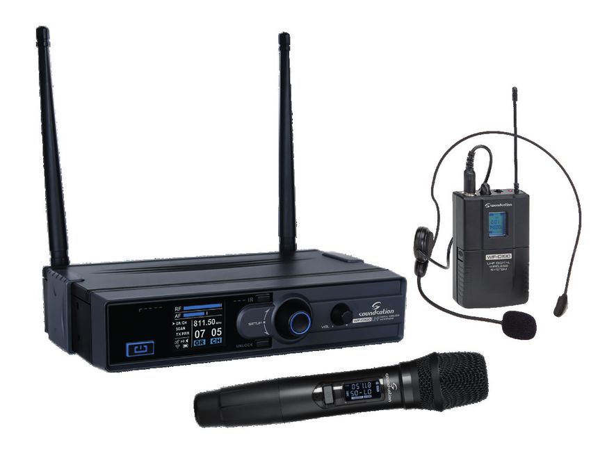
WF-D190 system is composed by following parts:
1.1. WF-D190H
ff 1x Receiver
ff 1x External Power Adapter
ff 1x Hand Transmitter
ff 1x 3.7V - 1200mAh Lithium Rechargeable Battery (type 18500)
ff 1x USB charge cable
ff This User Manual
1.2. WF-D190P
ff 1x Receiver
ff 1x External Power Adapter
ff 1x Pocket Transmitter
ff 1x Headset Microphone
ff 2x 1.5V AA-Type Batteries
ff This User Manual
ATTENTION: Packaging bag is not a toy! Keep out of reach of children!!! Keep in
a safe place the original packaging material for future use.
2. ACCESSORIES
SOUNDSATION can supply a wide range of quality accessories that you can use with
your WIREFREE Series wireless microphone system, like Cables, Mixers, Speakers, Am-
plifiers, Stands, etc.
All products in our catalogue has been long tested with this device so we recommend
to use Genuine SOUNDSATION Accessories and Spare Parts.
Ask your SOUNDSATION dealer for any accessories you could need to ensure best
performance of the product.
3. OVERVIEW
SOUNDSATION WF-D190 adopts a brand-new digital transmission technology and
hardware encryption of audio data that enable superior audio quality (compared to
analog UHF systems), very-low latency (better than 2.4GHz systems) and maximum
security due to the cryptographic hardware.
6ENGLISH
WF-D190 User manual
The unique 16bit digital ID pilot technology avoids interferences even on same fre-
quency, and allows continuous exchange of data between transmitter and receiver,
such as battery level, transmission power, squelch operation, etc.
The system is equipped with automatic frequency scanning and frequency spectrum
display, which allow the user to select the less disturbed frequencies in every envi-
ronment it operates. It features 90 frequencies, divided into 10 groups, each of which
contains 9 channels.
The user interface is very simple and intuitive, thanks to the TFT color display on
the receiver and the simplicity of its setup menus. The handheld transmitter and the
bodypack, however, are equipped with LCD display with auto-off function, to save bat-
tery. The handheld microphone is also equipped with rechargeable lithium battery that
can be recharged via the USB port on the back of the receiver.
Finally, there are two optional kit for rack mounting of 1 or 2 receivers, respectively, on
1 or 2 standard 19” rack units. Ask your dealer or visit SOUNDSATION website www.
soundsationmusic.com for further details.
WF-D190 systems are available in 2 configurations:
3.1. WF-D190H
• 1x UHF Digital Receiver
• 1x Hand Transmitter with Professional Dynamic Cardioid Capsule
3.2. WF-D190P
• 1x UHF Digital Receiver
• 1x Pocket Transmitter
• 1x Headset Microphone with Professional Dynamic Cardioid Capsule
4. MAIN FEATURES
ff UHF E-Band operation (823-832 MHz)
ff Digital audio transmission technology
ff Unique digital 16-bit ID pilot technology
ff Transmitter AF-level, Audio-level and Battery-Low monitoring on the Receiver
ff Double antenna diversity technology
ff No crosstalk disturbance even on same frequency
ff Ultra-short audio latency
ff 48kHz sampling frequency
ff 30-20kHz frequency response
ff Colorful TFT display and menu settings on receiver
7ENGLISH
WF-D190 User manual
ff Auto frequency scanning and spectrum display
ff 50m Ideal Distance (without obstacles)
ff Professional Handheld Microphone with Professional Dynamic Cardioid Capsule and
rechargeable Lithium Battery (WF-D190H only)
ff Body pack with Connector Locking System (WF-U190P model)
ff Professional and Lightweight Headset with High-Sensibility Dynamic Cardioid Cap-
sule (WF-D190P model)
ff Rack-Mount Kit for 1 or 2 receiver units to 1x or 2x 19” rack unit (optional)
5. RECEIVER CONTROLS AND FUNCTIONS
8 9
925.00 setup
01 01 vol
1 2 3 4 5 6 7
10 11 12 13
1. Power Switch: It switches on and off the receiver. Please notice that LOCK function
is active at power on. Hold SET button for a few seconds to unlock the receiver and
access to the parameters (refer to the section “8. SYSTEM INSTALLATION” at page
8ENGLISH
WF-D190 User manual
14 for details).
2. IR Sensor: It is the infrared sensor used to synchronize the operating channel be-
tween receiver and transmitter.
3. TFT Color Display: It shows all functions and allows easy and intuitive program-
ming of all parameters.
4. IR Switch: Press it to synchronize the operating channel between receiver and
transmitter.
5. Unlock Button: It locks/unlocks the system in order to avoid accidental setup
parameters changes.
6. Setup Knob/Button: It access to all editing functions, etc. (See section “8. SYSTEM
INSTALLATION” at page 14 for further details).
7. Volume Knob: It increases or decreases the output level of BALANCED and MIX
outputs.
8. Antenna-A: It receives RF signals from the transmitter.
9. Antenna-B: Same as Antenna-A, it receives RF signals from the transmitter.
10. Mix Output: It is the unbalanced audio line output with ¼” Jack to use in case of
connection to mixers or audio equipment with unbalanced connections.
11. Balance Output: It is the balanced XLR audio line output to connect to your mixer
or audio system. For more details about the internal wiring of balanced cables,
refer to paragraph “9. AUDIO CABLES” at page 18.
12. USB Charge Outlet:
13. DC Input: Connect here the external power supply (12Vdc – 1A)
5.1. Receiver Display
RF indicates signal intensity. AF indicates audio level. The longer the
bar is, the stronger the signal is
9ENGLISH
WF-D190 User manual
GR indicates current frequency group. CH indicates current frequen-
cy of the selected group
SCAN automatically scans up or down to search for available fre-
quency until the desired frequency is reached. It can be set under
SCAN function.
TX PWR shows only one icon: “HI” or “LO”. It indicates high or low
transmitter power
LOCK indicates that all buttons don’t operate under this status
HI / LO HI means high power. LO means low power
MUTE indicates that the receiver is under MUTE status (sound is off)
IR icon: when flashing indicates that the receiver is sending a SYNC
signal.
Battery icon: indicates the handheld/bodypack microphone battery
status.
6. HANDHELD MICROPHONE FUNCTIONS
WF-D190H system features a handheld transmitter with professional dynamic cardioid
capsule. Below there’s a quick description of main
parts.
1
1. Grille: It protects the microphone capsule.
Never remove it to prevent damage to the
2 internal parts of the microphone.
3 6
2. LCD Display: This back-lit display shows all
4 important information related to settings, as
well as the battery charge level.
NOTE: After about 10 seconds the back-light
5 is lowered, reducing battery consumption.
The lighting returns to increase each time
you press Power button.
3. IR Sensor: During IR synchronization procedure, bring this part of the transmitter
close to the receiver’s IR sensor to complete the operation.
4. Power button: Press and hold this button for about 2 seconds to turn on or off the
microphone.
5. Battery Slot: Insert the 3.7V - 1200mAh lithium rechargeable battery supplied
with the system, paying attention to correct polarity (indicated on bottom of this
battery compartment).
10ENGLISH
WF-D190 User manual
6. Battery Slot Cover: Remove this cover to access the battery-compartment and
insert or replace the batteries.
6.1. Handheld Microphone LCD Function
1) Indicates working channel
2) Indicates working group
3 2 1 3) In this case it Indicates Group 7, Ch05
4) Indicates mute status
4 Indicates using high or low transmitter
5) or
power
5 6 7 6) Indicates current frequency
Indicates battery status, when flashing
7)
indicates battery is low of power
6.2. Battery placement
ff Under working status, long press ON/OFF button until see OFF,
then the microphone is off.
ff Remove the battery cover, insert 1x18500 Lithium battery in cor-
rect polarity.
ff Long press ON/OFF button in 2 seconds. If LCD doesn’t light, check whether battery
in correct polarity or battery is low of power. If the battery indicator of LCD display is
flashing, please change with new battery.
NOTE: The microphone can only work under same frequency with Receiver. It
automatically enters the default mode when switched on, and automatically
save last used channels.
6.3. Hand-held Microphone Using Technique
ff Don’t hold the microphone grill.
ff Avoid holding the microphone on antenna position.
11ENGLISH
WF-D190 User manual
Antenna
position
Antenna
position
ff Don’t hold two microphones together
ATTENTION: Operating distance between microphone grill and mouth must be
less than 15cm
ff Avoid direct the microphone toward a speaker to avoid Larsen effect, which could
damage your audio system.
7. POCKET TRANSMITTER AND HEADSET
1. Microphone: WF-D190P system fea-
tures a headset microphone with pro-
fessional cardioid dynamic capsule.
2. Microphone Input: Plug here the
headset audio connector.
3. Volume: Adjust the audio input level
of the transmitter. Use this knob to
adapt microphone signal level in
order to prevent distorted sound.
4. ON/MUTE/OFF Selector: This selector
has 3 positions. When it’s all to the
OFF position, the microphone is
turned off; when it is MUTE position,
the microphone is active but the
audio is disabled; finally, when it’s all
to ON position, the microphone is
working and the audio is active.
12ENGLISH
WF-D190 User manual
NOTE: Standby central position allows the unit to transmit without audio. This
option is important to prevent interference in the receiver due to the absence
of a radio transmitting signal. It is, therefore, suggested to ALWAYS use this
standby position when you temporarily don’t sing or play but the wireless mi-
crophone is connected to an audio system (e.g. during a pause in a show). You
can move the switch to OFF position (all down) only when you are sure that the
sound system volume is low.
5. Power LED: It lights up when the transmitter is on.
6. Antenna: It transmits the radio signal. Be careful not to bend or break this terminal.
7. LCD Display: The back-lit display shows all important information relating to set-
tings, as well as battery charge level.
NOTE: After about 10 seconds the back-light is lowered, reducing battery
consumption. The lighting returns to increase each time you press the Power
button.
8. IR Sensor: During IR sync procedure, bring this part of the transmitter close to the
receiver’s IR sensor to complete the operation.
9. Battery Slot: Insert two 1.5V AA-Type batteries, paying attention to correct polarity
(indicated on bottom of this battery compartment). After that, pull the switch to
“ON” side, if LCD not light, check whether battery in correct polarity or is low of
power. If the battery indicator of LCD is flashing, please change with new batteries.
10. Battery Slot Cover: Open this cover to access to insert or replace the batteries.
Following the instructions for their replacement:
ff Apply a slight pressure at the top of the door (10) and pull down.
ff Insert or replace the batteries in the compartment, observing the +/- polarity marked
on the bottom.
ff Close the cover to prevent batteries to be lost during use.
7.1. Bodypack LCD Function
2 6 1 1) Indicates working channel
3 2) Indicates working group
3) In this case, it Indicates Group 01, Ch 01
4) Indicates current frequency
4
Indicates battery status, when flashing
5)
indicates that battery is low
5 6) Indicates mute status
13ENGLISH
WF-D190 User manual
8. SYSTEM INSTALLATION
8.1. Receiver Placement
Before using the system, please be
sure that the receiver is correctly
placed at a distance of about 1m from
floor, and 1m from walls or other big
physical obstacles (columns or other Beyond 1m
from walls
radio-frequency equipment).
ff Pull out the two antennas (8) and Beyond 1m
(9), make them to be perpendicu- from ground
lar with the receiver.
ff Connect the supplied power
adapter to the DC power supply
socket (13). Make sure that the
adapter is suitable before using
the Receiver.
ff Connect the balanced audio output (10) or the unbalanced (11) to your mixer or
sound system, using the appropriate cables (see section “9. AUDIO CABLES” at page
18 for further details).
ff Connect the USB charge cable (attached) to the USB socket (12) while the other side
connect to the handheld microphone. Charge battery until the display shows “FULL”,
meaning that the battery is successfully charged.
NOTE: Rechargeable function is available only on handheld microphones (WF-
D190H systems). Also notice that battery is charged even though the system in
switched off but connected to mains.
ff Turn on the receiver by pressing the POWER button (1); the LCD (3) will light up
showing the current settings of the system.
NOTE: Before switching on the Receiver, turn the volume control knob to mini-
mum, adjust the volume as needed when the Receiver is working.
Please notice that when you switch on the receiver LOCK function is active. Hold for
two seconds UNLOCK button to unlock it and have access to all parameters. LOCK
icon will turn off. In addition to the active LOCK function, at power on the receiver is
even muted ( icon is on) until you turn on the transmitter and align it on the same
receiver’s channel.
8.2. Group/Channel Manual Setting
After unlocking the receiver, the LOCK icon will turn off, indicating that you can select
14ENGLISH
WF-D190 User manual
one of the 10 groups and one of the 9 frequencies in each group.
Select menu icons Numbers change
ff Once you have located an interference-free channel (see “12. FREQUENCY TABLE”
at page 22 for details), rotate SETUP knob, and press it to enter into the channel
setting mode while GR/CH is highlighted.
ff Then rotate the control knob to select the appropriate menu item (GR or CH) and
press the knob to confirm.
ff Select the appropriate group and channel by increasing or decreasing and, after
finished, press the control knob to confirm.
ff Finally press IR function to sync the receiver with the handheld transmitter or
bodypack.
NOTE: If during group/channel selection you do not press any button for about
10 seconds, the system automatically returns to the LOCK mode. It is therefore
necessary to unlock the receiver again to re-access group/channel setup mode.
8.3. Auto Scan Mode
SOUNDSATION WF-D190 is equipped with a useful auto scan function of the frequen-
cies. This allows you to always choose those channels with less problems and make
setting operations extremely quick.
ff To automatically perform a frequency scan, unlock - if not already done - the receiver
by holding for a few seconds UNLOCK button (LOCK icon disappears).
ff Then press SETUP knob and rotate it clockwise or counterclockwise until SCAN menu
is reached.
ff Press SETUP knob again to enter SCAN menu. You fill find two options: UP or DOWN.
The first performs a spectrum scan and returns the first free frequency above the
current one. The second scans the spectrum but returns the first free frequency
below the current one.
ff Then rotate the control knob and select UP or DOWN to automatically scan up or
down to search for available frequency.
15ENGLISH
WF-D190 User manual
Select menu icons Spectrum analysis of environment
ff Once the frequency is reached, press IR button to transfer the certain Group/Chan-
nel information corresponding to the scanned frequency to bodypack or handheld
transmitter.
NOTE: If you do not press any buttons for about 10 seconds, the system returns
to LOCK mode.
8.4. Transmitter Power Setting
Transmitter power icon “HI” icon changes to “LO”
Adjust SETUP control knob, press TX PWR function enter into Transmitter HI/LO setting
mode. Then adjust the control knob, select high or low power (HI or L0) (3). Under the
situation of many equipment used together at the same time, select high power (HI)
can reduce mutual interference.
ff To adjust transmitter power, first unlock the receiver by holding for a few seconds
UNLOCK button (LOCK icon disappears).
ff Then press SETUP knob and rotate it clockwise or counterclockwise until TX PWR
menu is reached.
ff Press SETUP knob again to enter TX PWR menu. You fill find two options: HI and LO.
Then rotate the control knob and select one of the two options.
ff When LO icon flashes on receiver’s display, press UP or DOWN buttons to adjust
transmission power: “HI” stands for high power; “LO” stands for low power.
NOTE: Turn down the transmit power of a wireless system may seem a contra-
diction. Normally radio interference cause audio noises because of poor power,
but this is not always true. In fact, sometimes a transmitter too close to the
16ENGLISH
WF-D190 User manual
receiver can create problems. In these cases, it may be better to reduce trans-
mission power in order to cancel these problems.
8.5. IR Sync Function
The WF-D190 comes with an infrared transmission system between receiver and trans-
mitter that easily sends all settings to your hand-held or pocket transmitter. To activate
the IR function:
ff Turn on the receiver and hold for a few seconds UNLOCK key to unlock it. LOCK
icon will turn off. Now you can choose between manual channel setting or auto scan
procedure to find the best frequency to be used.
Manual Channel Setting
ff Once you have located an interference-free channel (please refer to “12. FREQUEN-
CY TABLE” at page 22), rotate SETUP knob, and press it to enter into channel set-
ting mode while GR/CH is highlighted.
ff Rotate control knob again to select the appropriate menu item (GR or CH) and press
the knob to confirm.
ff Select the appropriate group and channel by increasing or decreasing and, after
finished, press the control knob to confirm.
ff Finally press for about 2 seconds IR button to sync the receiver to the handheld
transmitter or bodypack. icon will flash for about 15 seconds, indicating that the
receiver unit is sending the information through the IR sensor.
ff Bring the handheld or pocket transmitter as close as possible to the receiver’s IR
sensor.
setup setup
vol vol
ff Once the transmitter is synchronized, icon stops blinking; MUTE icon turns off,
battery and transmission power HI or LO icons light up, indicating that the sys-
17ENGLISH
WF-D190 User manual
tem is now working properly.
ff The display on the transmitter shows the same channel set on the receiver and the
HI or LO icons indicate a good radio signal.
ff After about 10 seconds, the system automatically returns to LOCK mode. At this
point the system is fully set and ready to operate.
Auto Scan Setting
If you want the system automatically suggest interference-free frequencies, then per-
form the auto scan procedure as already shown in paragraph “8.3. Auto Scan Mode” at
page 15.
ff Press SETUP knob and rotate it clockwise or counterclockwise until SCAN menu is
reached.
ff Rotate the control knob again and select UP or DOWN to automatically scan up or
down for available frequencies.
ff Once the frequency is reached, press for about 2 seconds IR button to transfer the
Group/Channel information corresponding to the scanned frequency to bodypack
or handheld transmitter. icon will flash for about 15 seconds, indicating that the
receiver unit is sending the information through the IR sensor.
ff Bring the handheld or pocket transmitter as close as possible to the receiver’s IR
sensor.
ff Once the transmitter is synchronized, icon stops blinking; MUTE icon turns off,
battery and transmission power HI or LO icons light up, indicating that the sys-
tem is now working properly.
ff The display on the transmitter shows the same channel set on the receiver and the
HI or LO icons indicate a good radio signal.
ff After about 10 seconds, the system automatically returns to LOCK mode. At this
point the system is fully set and ready to operate.
9. AUDIO CABLES
You need XLR balanced cables for connections to your audio equipment. See the
pictures below that show the internal wiring of these cables. Be sure to use only high
quality cables (visit our website www.soundsationmusic.com for further details).
Balanced use of XLR connectors Balanced use of 1/4” jack TRS connector
Strain relief
1= Ground/Shield clamp Sleeve
Tip
2= Hot (+) Ground shield
Hot (+ Ve)
3= Cold (-) Sleeve
Ring Ring
Tip Cold (- Ve)
INPUT OUTPUT
In case of unbalanced use Pins 1 and 3 will be jumped
18ENGLISH
WF-D190 User manual
You can, of course, connect even unbalanced equipment to balanced outputs. Use ei-
ther mono and stereo jack, making sure ring and collar are connected together (or pins
1 & 3 in the case of XLR connectors).
Unbalanced use of 1/4” jack TS connector
Strain relief
clamp
Sleeve Tip
Ground shield Signal
Sleeve
Tip
10. WF-RACK KIT1
WF-D190 receiver unit can be mounted into 19” standard rack units using an optional
kit (contact your dealer or go to www.soundsationmusic.com for more details) to adapt
the receiver to one 19” rack unit.
setup
vol
The kit includes:
A. 2x ¼ rack unit adapter
B. 2x Extension cables for Antenna
C. 4x Screws to fasten the receiver to the two rack adapters
NOTE: The kit doesn’t include screws to fasten the whole block (receiver and
adapters) to the 19” rack chassis. About the extension antenna cables, they
are not used with the WF-D190 as its antenna is not detachable.
10.1. WF-RACK KIT1 Assembling
1. Remove the two plastic parts on each of the two sides of the receiver.
2. Place the A adapter so that the two lateral holes match those on the receiver side.
3. Fasten the adapter using two screws as shown in the picture.
4. Repeat steps 1 to 3 of this section on the other side of the receiver.
19ENGLISH
WF-D190 User manual
5. Place two rear antenna in horizontal position.
4
1
5
2
3
20ENGLISH WF-D190 User manual 11. SPECIFICATIONS SYSTEM Carrier Frequency: UHF823-832MHz Bandwidth: 9MHz Channel Bandwidth: 100kHz Preset Group/Channel: 10 groups, 9 frequencies in each group Dynamic Range: >98dB Total Harmonic Distortion: 98dB Receiving Sensitivity: -95dBm Transmission Delay:
ENGLISH
                                                             WF-D190 User manual

   12. FREQUENCY TABLE
   E-Band (823-832 MHz)

                                             CHANNEL
                   1       2       3       4       5       6       7       8       9
             1   823,0   824,0   825,0   826,0   827,0   828,0   829,0   830,0   831,0
             2   823,4   824,4   825,4   826,4   827,4   828,4   829,4   830,4   831,4
             3   823,9   824,9   825,9   826,9   827,9   828,9   829,9   830,9   831,9
             4   823,1   824,1   825,1   826,1   827,1   828,1   829,1   830,1   831,1
             5   823,5   824,5   825,5   826,5   827,5   828,5   829,5   830,5   831,5
     BANK

             6   823,8   824,8   825,8   826,8   827,8   828,8   829,8   830,8   831,8
             7   823,2   824,2   825,2   826,2   827,2   828,2   829,2   830,2   831,2
             8   823,6   824,6   825,6   826,6   827,6   828,6   829,6   830,6   831,6
             9   823,3   824,3   825,3   826,3   827,3   828,3   829,3   830,3   831,3
            10   823,7   824,7   825,7   826,7   827,7   828,7   829,7   830,7   831,7

   22
ENGLISH
WF-D190 User manual
13. WARRANTY AND SERVICE
All SOUNDSATION products feature a limited two-year warranty. This two-year warranty is specific
to the date of purchase as shown on your purchase receipt.
The following cases/components are not covered from the above warranty:
• Any accessories supplied with the product
• Improper use
• Fault due to wear and tear
• Any modification of the product effected by the user or a third party
SOUNDSATION shall satisfy the warranty obligations by remedying any material or manufacturing
faults free of charge at SOUNDSATION’s discretion either by repair or by exchanging individual
parts or the entire appliance. Any defective parts removed from a product during the course of a
warranty claim shall become the property of SOUNDSATION.
While under warranty period, defective products may be returned to your local SOUNDSATION
dealer together with original proof of purchase. To avoid any damages in transit, please use the
original packaging if available. Alternatively you can send the product to SOUNDSATION SERVICE
CENTER – Via Enzo Ferrari , 10 – 62017 Porto Recanati - Italy . In order to send a product to service
center you need an RMA number. Shipping charges have to be covered by the owner of the prod-
uct.
For further information please visit www.soundsationmusic.com
14. WARNING
PLEASE READ CAREFULLY – EU and EEA (Norway, Iceland and Liechtenstein) only
This symbol indicates that this product is not to be disposed of with your household waste, ac-
cording to the WEEE Directive (2202/96/EC) and your national law.
This product should be handed over to a designated collection point, e.g., on an authorized one-
for-one basis when you buy a new similar product or to an authorized collection site for recycling
waste electrical and electronic equipment (WEEE).
Improper handling of this type of waste could have a possible negative impact on the environment
and human health due to potentially hazardous substances that are generally associated with EEE.
At the same time, your cooperation in the correct disposal of this product will contribute to the
effective usage of natural resources.
For more information about where you can drop off your waste equipment for recycling, please
contact your local city office, waste authority, approved WEEE scheme or your household waste
disposal service.
23ITALIANO SOMMARIO 15. DISIMBALLAGGIO....................................................................................................26 15.1. WF-D190H...............................................................................................................................................................26 15.2. WF-D190P................................................................................................................................................................27 16. ACCESSORI................................................................................................................27 18. INTRODUZIONE........................................................................................................28 18.1. WF-D190H...............................................................................................................................................................28 18.2. WF-D190P................................................................................................................................................................28 19. CARATTERISTICHE....................................................................................................28 20. CONTROLLI E FUNZIONI DEL RICEVITORE............................................................29 20.1. Display del Ricevitore..........................................................................................................................................31 21. FUNZIONI DEL MICROFONO PALMARE.................................................................31 21.1. Funzioni dell’LCD del Microfono a mano....................................................................................................32 21.2. Posizionamento della batteria.........................................................................................................................32 21.3. Uso corretto del Trasmettitore Palmare.......................................................................................................33 22. TRASMETTITORE TASCABILE..................................................................................34 22.1. Funzioni dell’LCD del bodypack......................................................................................................................35 23. INSTALLAZIONE DEL SISTEMA...............................................................................36 23.1. Posizionamento del Ricevitore........................................................................................................................36 23.2. Impostazione manuale Gruppo/Canale.......................................................................................................37 23.3. Modalità di Scansione Automatica................................................................................................................37 23.4. Impostazione della potenza del trasmettitore..........................................................................................38 23.5. Funzione di sincronizzazione IR......................................................................................................................39 24. CONNESSIONI AUDIO..............................................................................................41 25. WF-RACK KIT1..........................................................................................................41 25.1. Installare il WF-RACK KIT1.................................................................................................................................42 26. SPECIFICHE................................................................................................................43 27. TAVOLA DELLE FREQUENZE....................................................................................44 28. GARANZIA E ASSISTENZA.......................................................................................45 29. AVVISO......................................................................................................................45 30. DECLARATION OF CONFORMITY...........................................................................46 24
ITALIANO
Manuale d’uso WF-D190

IMPORTANTI SIMBOLI DI SICUREZZA

                Il simbolo è usato per indicare che in questa apparecchiatura sono
                presenti alcuni terminali sotto tensione pericolosi, anche in condizioni
                di normale funzionamento, che possono costituire rischio di scosse
                elettriche o di morte.
                Il simbolo viene utilizzato nella documentazione di servizio per indi-
                care che uno specifico componente può essere sostituito esclusiva-
                mente dal componente specificato nella documentazione per motivi di
                sicurezza.

                Terminale di Terra

                Corrente/Tensione alternata

                Terminale in tensione pericoloso

                Indica che l’apparato è acceso
                Indica che l’apparato è spento
                Precauzioni da osservare per evitare il pericolo di ferimento o di morte
 WARNING:       per l’utilizzatore.
 CAUTION:       Precauzioni da osservare per evitare danni all’apparecchio.

IMPORTANTI ISTRUZIONI DI SICUREZZA
ff Leggete queste istruzioni
ff Conservate queste istruzioni
ff Rispettate tutte le avvertenze
ff Seguite tutte le istruzioni

Acqua e Umidita
L’apparecchio deve essere protetto dall’umidità e dalla pioggia, non può essere usato
in prossimità di acqua; ad esempio nei pressi di una vasca da bagno, di un lavandino, di
una piscina, etc.
Calore
L’apparecchio deve essere posto lontano da fonti di calore come radiatori, stufe o altri
apparecchi che producono calore.

                                                                                      25
ITALIANO
Manuale d’uso WF-D190
Ventilazione
Non ostruite le prese d’aria per la ventilazione: ciò potrebbe provocare incendi. Instal-
late sempre l’unità secondo le istruzioni del produttore.
Introduzione di oggetti e liquidi
Non introdurre oggetti o versare liquidi all’interno dell’apparato per ragioni di sicurez-
za.
Alimentazione
L’apparecchio deve essere collegato alla sorgente di alimentazione elettrica del tipo
indicato sull’apparecchio o descritto nel manuale. In caso contrario si potrebbero
provocare danni al prodotto ed eventualmente all’utente. Staccate la spina in caso di
temporali o quando non viene utilizzato per lunghi periodi di tempo.
Collegamento alla rete elettrica
Il collegamento elettrico improprio può invalidare la garanzia del prodotto.
Pulizia
Pulite solo con un panno asciutto. Non utilizzate solventi come benzolo o alcol.
Manutenzione
Non effettuate qualsiasi altro intervento al di fuori di quelli descritti nel manuale. Per
eventuale assistenza rivolgetevi solo a personale qualificato. Utilizzate solo accessori /
componenti suggeriti dal produttore.
Avviso
Vogliamo ricordare che un’alta pressione sonora non solo può danneggiare tempora-
neamente il senso dell’udito, ma può anche causare danni permanenti. Prestate atten-
zione affinché il volume sia sempre adeguato.
Interferenze DOVUTE A TELEFONI Cellulari
Usare telefoni cellulari vicino ad un radiomicrofono può causare rumori in audio. Se ciò
avviene, allontanate il cellulare dai componenti del radiomicrofono.
15. DISIMBALLAGGIO
Il sistema a radiomicrofono WF-D-190 è composto dai seguenti componenti:
15.1. WF-D190H
ff 1x Ricevitore
ff 1x Alimentatore esterno
ff 1x Trasmettitore a mano
ff 1x Batteria Ricaricabile al Litio da 3.7V-1200mAh (tipo 18500)
ff 1x cavo USB
26ITALIANO
Manuale d’uso WF-D190
ff Questo Manuale
15.2. WF-D190P
ff 1x Ricevitore
ff 1x Alimentatore esterno
ff 1x Trasmettitore tascabile
ff 1x Microfono ad archetto
ff 2x Batterie Stilo da 1.5V tipo AA
ff 2x Antenne
ff Questo Manuale
ATTENZIONE: L’imballo non è un giocattolo! Tienilo fuori dalla portata dei
bambini!!! Conserva tutte le parti dell’imballo per un futuro utilizzo.
16. ACCESSORI
SOUNDSATION è in grado di fornire un ampia gamma di accessori utili per l’utilizzo
dei radiomicrofoni WIREFREE, come ad esempio Cavi, Mixer, Diffusori, Amplificatori,
Supporti per casse, ecc.
Tutti gli articoli presenti a catalogo e compatibili sono stati testati professionalmente
dal nostro team, quindi raccomandiamo vivamente di utilizzare prodotti ed accessori
originali SOUNDSATION.
Chiedi al tuo negoziante autorizzato SOUNDSATION la lista degli accessori originali
compatibili, in questo modo ti assicurerai una performance ottimale.
17.
27ITALIANO
Manuale d’uso WF-D190
18. INTRODUZIONE
Il sistema SOUNDSATION WF-D190 adotta una nuova tecnologia di trasmissione
digitale e cifratura hardware dei dati audio che consentono una qualità audio superiore
(rispetto ai sistemi analogici UHF), la latenza molto bassa (meglio di sistemi a 2,4 GHz)
e la massima sicurezza grazie alla crittografia hardware
La tecnologia digitale ID a 16bit evita interferenze anche sulla stessa frequenza, e
consente lo scambio continuo di dati tra trasmettitore e ricevitore, come il livello della
batteria, la potenza di trasmissione, operazione di squelch, etc.
Il sistema è dotato di scansione automatica e visualizzazione dello spettro di frequenza,
che permettono all’utente di selezionare le frequenze meno disturbati in ogni ambiente
in cui opera. È dotato di 90 frequenze, divisi in 10 gruppi, ciascuno dei quali contiene 9
canali.
L’interfaccia utente è molto semplice ed intuitiva, grazie al display TFT a colori del
ricevitore e la semplicità dei suoi menu di impostazione. Il trasmettitore a mano e il
body-pack, invece, sono dotati di display LCD con funzione di spegnimento automatico,
per risparmiare la batteria. Il microfono palmare è inoltre dotato di batteria al litio
ricaricabile che può essere ricaricata tramite la porta USB sul retro del ricevitore.
Infine, ci sono due kit opzionali per il montaggio a rack di 1 o 2 ricevitori,
rispettivamente, 1 o 2 standard da 19 “unità rack. Chiedete al vostro rivenditore o
visitare il sito web SOUNDSATION www.soundsationmusic.com per ulteriori dettagli.
I sistemi WF-D190 sono disponibili in 2 diverse configurazioni:
18.1. WF-D190H
• 1x Ricevitore digitale UHF
• 1x Trasmettitore Palmare con Capsula Dinamica Cardioide Professionale
18.2. WF-D190P
• 1x Ricevitore digitale UHF
• 1x Trasmettitore Tascabile
• 1x Microfono ad Archetto con Capsula Dinamica Cardioide Professionale
19. CARATTERISTICHE
ff Banda UHF 823-832MHz
ff Tecnologia di trasmissione audio digitale
ff Tecnologia Digital Pilot 16 bit
ff Monitoraggio del livello di segnale AF e della carica delle batterie direttamente sul
28ITALIANO
Manuale d’uso WF-D190
ricevitore
ff Doppia antenna con tecnologia diversity
ff Nessuna interferenza anche sulla stessa frequenza
ff Latenza audio ultra-ridotta
ff Frequenza di campionamento 48kHz
ff Risposta in frequenza 30-20Hz
ff Impostazioni di visualizzazione e di menu TFT colorati sul ricevitore
ff Scansione di frequenza automatica e visualizzazione dello spettro
ff Distanza ideale 50m (senza ostacoli)
ff Microfono palmare professionale con capsula dinamica cardioide Professionale e
batteria al litio ricaricabile (WF-D190H solo)
ff Trasm. tascabile con connettore dotato di sistema di bloccaggio (modello WF-U190P)
ff Archetto professionale e leggero con capsula dinamica cardioide professionale ad
alta sensibilità (modello WF-D190P)
ff Kit di montaggio a rack per 1 o 2 unità ricevitore a 1x o 2x unità rack 19 “(opzionale)
20. CONTROLLI E FUNZIONI DEL RICEVITORE
8 9
925.00 setup
01 01 vol
1 2 3 4 5 6 7
1. Tasto Power: accende e spegne il ricevitore. Tenete presente che all’accensione
la funzione LOCK è attiva. Tenere premuto per qualche secondo il tasto SET per
sbloccare il ricevitore e avere accesso ai parametri (fate riferimento al paragrafo
10 11 12 13 29ITALIANO
Manuale d’uso WF-D190
“23. INSTALLAZIONE DEL SISTEMA” a pagina 36 per ulteriori dettagli).
2. Sensore IR: è il sensore a infrarossi utilizzato per sincronizzare il canale operativo
tra il ricevitore e trasmettitore
3. Display TFT a colori: Esso mostra tutte le funzioni e consente la programmazione
facile ed intuitiva di tutti i parametri.
4. Interruttore IR: premere per sincronizzare il canale operativo tra ricevitore e tra-
smettitore.
8 9
5. Bottone di Sblocco: Si blocca / sblocca il sistema al fine di evitare accidentali dei
parametri di configurazione modifiche.
6. Impostazione manopola/pulsante: l’accesso a tutte le funzioni di editing, ecc (vedi
sezione “8. INSTALLAZIONE DEL SISTEMA” a pagina 35 per ulteriori dettagli).
7. Manopola VOLUME: Aumenta o diminuisce il livello di uscita delle uscite BALAN-
CED e MIX. 925.00 setup
01 01
8. ANTENNA A: Riceve il segnale RM dal trasmettitore
vol
9. 1 l’antenna
ANTENNA B: Come 2 3 A, riceve
4 il segnale
5 6 RF dal
7 trasmettitore.
10 11 12 13
10. Uscita MIX: È l’uscita audio sbilanciata di linea con Jack da ¼” da usare nel caso di
collegamento a mixer o impianti audio con connessioni sbilanciate.
11. Uscita bilanciata: E’ la linea audio bilanciata di uscita XLR per la connessione al
mixer o ad un sistema audio. Per ulteriori dettagli sul cablaggio interno di cavi
bilanciati, fare riferimento al paragrafo “9. Cavi audio “a pagina ......
12. Presa USB: Connettere qui il cavo USB in dotazione per la ricarica della batteria del
trasmettitore palmare.
13. Presa di Alimentazione: Collegare qui l’adattatore di rete in dotazione.
30ITALIANO
Manuale d’uso WF-D190
20.1. Display del Ricevitore
RF indicata l’intensità del segnale. AF indica il livello dell’audio. Più
lunga è la barra, più forte è il segnale
GR indica il gruppo di frequenza corrente. CH indica la frequenza
corrente del gruppo selezionato
SCAN scansione automatica per verificare la frequenza disponibile
fino a raggiungere la frequenza desiderata. Può essere impostato in
funzione di scansione.
TX PWR mostra solo una icona: “HI” o “LO”. Indica se la potenza del
ricevitore è alta o bassa
LOCK indica che tutti i pulsanti non funzionano in questo stato
HI / LO HI significa high power. LO significa low power
MUTE indica che il ricevitore è in stato di MUTE (il suono è spento)
Icona IR: quando lampeggia indica che il ricevitore sta inviando un
segnale SYNC.
Icona Batteria: indica lo stato della batteria del microfono palmare/
bodypack.
21. FUNZIONI DEL MICROFONO PALMARE
Il sistema WD-D190H è dotato di un trasmettitore a
mano con capsula cardioide professionale dinamica. 1
Qui di seguito c’è una rapida descrizione delle parti
principali
2
3 6
1. Griglia: protegge la capsula del microfono. Non
rimuoverla mai al fine di prevenire danneggia- 4
menti alle parti interne del microfono
2. Display LCD: Questo display retroilluminato vi-
sualizza tutte le informazioni importanti relative 5
alle impostazioni, così come il livello di carica
31ITALIANO
Manuale d’uso WF-D190
della batteria.
NOTA: Dopo circa 10 secondi la retroilluminazione si abbassa, riducendo il
consumo della batteria. L’illuminazione torna ad aumentare ogni volta che si
preme il pulsante di alimentazione.
ff Sensore IR: Durante la procedura di sincronizzazione IR, portare questa parte del
trasmettitore vicino al sensore IR del ricevitore per completare l’operazione.
ff Pulsante di alimentazione: Premere e tenere premuto questo pulsante per circa 2
secondi per attivare o disattivare il microfono
ff Slot della batteria: Inserire la batteria ricaricabile al litio da 3.7V - 1200mAh in dota-
zione con il sistema, prestando attenzione alla corretta polarità (indicata sul fondo
di questo vano batterie).
ff Coperchio della Slot: Rimuovere questo coperchio per accedere al vano batteria e
inserire o sostituire le batterie.
21.1. Funzioni dell’LCD del Microfono a mano
1) Indica il canale attivo
2) Indica il gruppo attivo
3 2 1
3) In questo caso indica Group7, Ch05
4) Indica lo stato di Mute
4
Indica se il trasmettitore è in alta o
5) or
bassa frequenza
5 6 7 6) Indica la frequenza corrente
Indica lo stato della batteria, quando
7) lampeggia indica che la batteria è
quasi esaurita
21.2. Posizionamento della batteria
ff In condizione di funzionamento, premere a lungo il pulsante ON/
OFF fino a vedere OFF, poi il microfono è spento.
ff Rimuovere il coperchio della batteria, inserire una batteria al litio
1x18500 nella corretta polarità.
ff Premere al lungo il tasto ON/OFF per 2 secondi. Se il display LCD non si accende, ve-
rificare se la batteria è in polarità corretta o se è scarica. Se l’indicatore della batteria
del display LCD lampeggia, si prega di cambiare la batteria con una nuova.
NOTA: Il microfono può funzionare solo con la stessa frequenza del ricevito-
re. Si entra automaticamente in modalità predefinita quando viene acceso,
ed automaticamente vengono salvati gli ultimi canali utilizzati.
32ITALIANO
Manuale d’uso WF-D190
21.3. Uso corretto del Trasmettitore Palmare
ff Non impugnare la capsula del microfono.
ff Evitare di tenere il microfono sulla posizione dell’antenna.
Posizione
dell’antenna
Posizione
dell’antenna
ff Non tenere due microfoni insieme
ATTENZIONE: La distanza operativa tra la griglia del microfono e la bocca
deve essere inferiore a 15 centimetri.
ff Non direzionare il microfono verso un altoparlante per evitare l’effetto Larsen, che
potrebbe danneggiare il sistema audio.
33ITALIANO
Manuale d’uso WF-D190
22. TRASMETTITORE TASCABILE
1. Microfono: Il sistema WF-D190P
dispone di un microfono con
auricolare con capsula dinamica
cardioide professionale.
2. Ingresso microfono: Inserire qui il
connettore audio auricolare.
3. Volume: Regolare il livello di ingresso
audio del trasmettitore. Utilizzare
questa manopola per adattare il
livello del segnale del microfono in
modo da evitare suono distorto.
4. Selettore ON/MUTE/OFF: Questo
selettore ha 3 posizioni. Quando è
tutto in posizione OFF, il microfono è
spento; quando è in posizione MUTE,
il microfono è attivo ma l’audio è
disabilitato; infine, quando è tutto
in posizione ON, il microfono sta
lavorando e l’audio è attivo
NOTA: La posizione centrale di stand-by permette all’unità di trasmette-
re senza audio. Questa opzione è importante per evitare interferenze nel
ricevitore per l’assenza di un segnale radio trasmittente. Quindi, si suggerisce
di utilizzare SEMPRE la posizione di stand-by quando non si canta o non si
suona temporaneamente, ma il microfono senza fili è collegato ad un sistema
audio (ad esempio, durante una pausa in uno spettacolo). È possibile spo-
stare l’interruttore in posizione OFF (tutto giù) solo quando si è certi che il
volume del sistema audio è basso.
5. Power LED: Si accende quando il trasmettitore è acceso.
6. Antenna: Trasmette il segnale radio. Fare attenzione a non piegare o rompere
questo terminale.
7. Display LCD: Il display retroilluminato visualizza tutte le informazioni importanti
relative alle impostazioni, così come il livello di carica della batteria.
NOTE: Dopo circa 10 secondi la retroilluminazione si abbassa, riducendo il
consumo della batteria. L’illuminazione torna ad aumentare ogni volta che si
preme il pulsante di accensione.
8. Sensore IR: Durante la procedura di sincronizzazione IR, portare questa parte del
trasmettitore vicino al sensore IR del ricevitore per completare l’operazione.
34ITALIANO
Manuale d’uso WF-D190
9. Slot della batteria: Inserire due batterie da 1.5V tipo AA, prestare attenzione
alla corretta polarità (indicata sul fondo del vano batteria). Dopo di che, girare
l’interruttore su “ON”, se l’LCD si illumina, verificare se la batteria è nella corretta
polarità o se la batteria è scarica. Se l’indicatore LCD della batteria lampeggia, si
prega di sostituire le batterie con delle batterie nuove.
10. Coperchio della Slot: Aprire questo coperchio per poter inserire o sostituire le
batterie. Seguire le istruzioni per la sostituzione:
ff Applicare una leggera pressione sulla parte superiore della porta (10) e tirare giù.
ff Inserire o sostituire le batterie nel vano rispettando la polarità +/- indicata sul fondo.
ff Chiudere il coperchio per impedire di perdere le batterie durante l’uso.
22.1. Funzioni dell’LCD del bodypack
2 1) Indica il canale attivo
6 1
3 2) Indica il gruppo attivo
3) In questo caso indica Gruppo 01, Canale 01
4) Indica la frequenza corrente
4
Indica lo stato della batteria, quando lam-
5)
peggia indica che la batteria è bassa
5 6) Indica lo stato del mute
ff Quando l’icona POWER lampeggia sul display del ricevitore (di solito è seguita dall’i-
cona LO), premere i tasti UP o DOWN per regolare la potenza di trasmissione: “HI”
significa potenza sufficiente; “LO” potenza scarsa.
NOTA: Può sembrare una contraddizione il fatto che sia possibile “abbassa-
re” la potenza di trasmissione di un radiomicrofono. Di solito le interferenze
accadono perché la potenza è scarsa. Ciò non è sempre vero; infatti a volte
un trasmettitore troppo vicino al ricevitore può creare dei problemi. In questi
casi può essere opportuno diminuire la potenza di trasmissione per annullare
tali inconvenienti.
35You can also read