User Manual Blizzard Revision 02.6 February 2020 Tempest Lighting, Inc - Outdoor Projector Enclosures | Tempest
←
→
Page content transcription
If your browser does not render page correctly, please read the page content below
User Manual
                            Blizzard
                                Revision 02.6
                              February 2020
                       © Tempest Lighting, Inc.

Blizzard User Manual                          1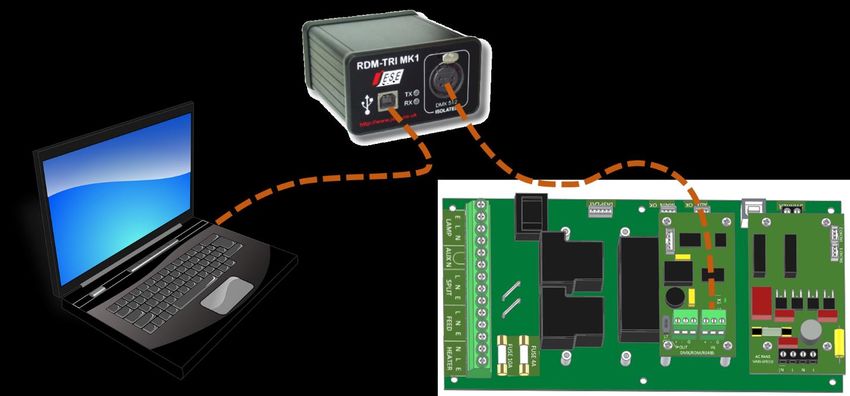
Table of Contents
    Approvals – Europe ................................................................................................................................................................................ 5
    Approvals – China ................................................................................................................................................................................... 6
Introduction ................................................................................................................................................................................................ 7
    IMPORTANT: Safety Advisories .............................................................................................................................................................. 7
Installation................................................................................................................................................................................................... 8
    Dimensions, Rigging Points, and Maximum Projector Dimensions/Power ......................................................................................... 8
        Projector Maximum Dimensions & Power ........................................................................................................................................ 9
        Air Clearance....................................................................................................................................................................................... 9
        Snow Clearance .................................................................................................................................................................................. 9
        Mounting Bolts ................................................................................................................................................................................. 10
        Mounting Options – Stacking Kit ..................................................................................................................................................... 11
        Mounting Options – Unistrut Kit ..................................................................................................................................................... 11
        Mounting Options – Cyclovator....................................................................................................................................................... 11
        Mounting Options – Horizontal Pole Hanger Kit ............................................................................................................................ 12
        Mounting Options – Vertical Pole Hanger Kit ................................................................................................................................. 12
        Mounting Options – Desert Filter Baffle ......................................................................................................................................... 13
Wiring the Enclosure ................................................................................................................................................................................ 13
    Power Wiring ........................................................................................................................................................................................ 13
        SAFETY NOTICE: ................................................................................................................................................................................ 13
        Electrical Standards .......................................................................................................................................................................... 13
        Wiring Access.................................................................................................................................................................................... 14
        One or Two Power Circuits? ............................................................................................................................................................ 15
        Conduit Entries ................................................................................................................................................................................. 16
        Single Feed Power Termination ....................................................................................................................................................... 17
        Split Feed Power Termination ......................................................................................................................................................... 17
    Remote Monitoring Connections ........................................................................................................................................................ 18
        RS485 (DMX/RDM) Cable Terminations .......................................................................................................................................... 19
        Line Termination Switch Settings .................................................................................................................................................... 20
    DEC4 Ethernet Adapter – 51.EN .......................................................................................................................................................... 21
        Default Configuration ....................................................................................................................................................................... 21
        Additional Support ........................................................................................................................................................................... 21
        Tempest Equipment Management Protocol .................................................................................................................................. 22
        Projector Power Control using DMX512 ......................................................................................................................................... 23
        DMX/RDM Network, using JESE RDM-TRI ....................................................................................................................................... 24
    Positive Pressure Fan Control Option .................................................................................................................................................. 25
Mounting the Projector ............................................................................................................................................................................ 26
    Landscape & Portrait Enclosures – fixed or slide? Tabletop or ceiling? ............................................................................................ 26

Blizzard User Manual                                                                                                                                                                                           2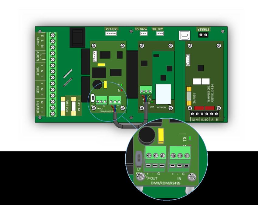
Projector Fixed or Slide Mounting ................................................................................................................................................... 26
       Ceiling or Tabletop ........................................................................................................................................................................... 26
   Projector Slide Direction ...................................................................................................................................................................... 27
       Reversing Slide Direction ................................................................................................................................................................. 27
   Mount the Projector – Fixed Mount.................................................................................................................................................... 28
       Tabletop Installation......................................................................................................................................................................... 28
   Mount the Projector – Slide Mounts ................................................................................................................................................... 28
       Aligning and Securing the Projector ................................................................................................................................................ 30
   Projector Mount – Portrait .................................................................................................................................................................. 31
       Changing Portrait Orientation ......................................................................................................................................................... 32
       Projector Mount – Ultra-Short-Throw ............................................................................................................................................ 33
Digital Enclosure Control .......................................................................................................................................................................... 34
   Schematic .............................................................................................................................................................................................. 34
   DEC4 Main Functions ........................................................................................................................................................................... 35
       Firmware Revision ............................................................................................................................................................................ 35
   Factory Settings – Data Modes ............................................................................................................................................................ 35
   Hardware Indicators & Fuses ............................................................................................................................................................... 36
   Operating Modes .................................................................................................................................................................................. 37
       RDM Only Monitor (Factory Default) .............................................................................................................................................. 37
       RDM+DMX Control ........................................................................................................................................................................... 37
       RDM+DMX Service ........................................................................................................................................................................... 37
   DEC4 Control Parameters .................................................................................................................................................................... 38
       Control Interface .............................................................................................................................................................................. 39
       User Interface LCD Display ............................................................................................................................................................... 40
       Control Interface Operation ............................................................................................................................................................ 40
   Control Menu ........................................................................................................................................................................................ 41
       Set Data Options............................................................................................................................................................................... 41
       Set Temp Units ................................................................................................................................................................................. 42
       Set Temp Ranges .............................................................................................................................................................................. 42
       Set Max Humidity ............................................................................................................................................................................. 42
       Set Lamp On Point ............................................................................................................................................................................ 42
       Reset Lamp Hours............................................................................................................................................................................. 42
       Set Fan Function ............................................................................................................................................................................... 43
       Status Display.................................................................................................................................................................................... 43
   Safe Mode ............................................................................................................................................................................................. 44
       Safe Mode – What to do: ................................................................................................................................................................. 44
DEC4 Firmware Updates .......................................................................................................................................................................... 46
   Indirect Firmware Updates .................................................................................................................................................................. 46
       Requirements ................................................................................................................................................................................... 46

Blizzard User Manual                                                                                                                                                                                        3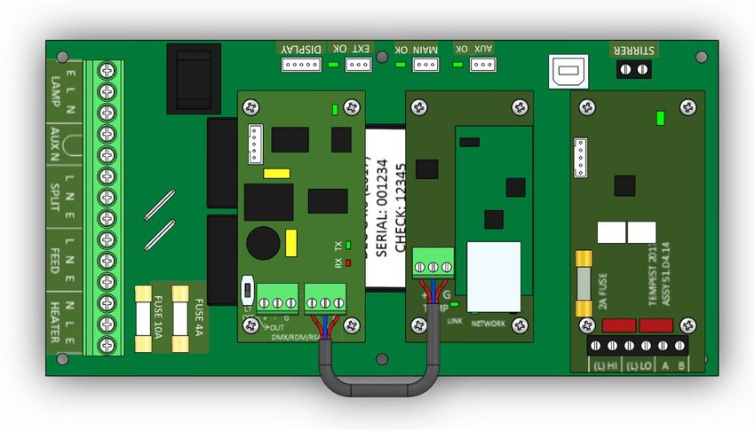
Installation Procedure ...................................................................................................................................................................... 46
Routine Maintenance ............................................................................................................................................................................... 51
       Clean Port Glass ................................................................................................................................................................................ 51
       Check Filter ....................................................................................................................................................................................... 51
       Check Temperature/Humidity Sensor ............................................................................................................................................. 52
       For After Sales Support .................................................................................................................................................................... 52
Troubleshooting ........................................................................................................................................................................................ 53
Warranty ................................................................................................................................................................................................... 54
Appendix – TEMP Protocol ....................................................................................................................................................................... 55
   Physical Layer ........................................................................................................................................................................................ 55
   Developer’s Guide ................................................................................................................................................................................ 55

Blizzard User Manual                                                                                                                                                                                         4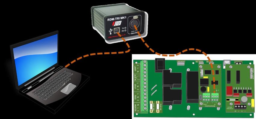
Approvals – Europe

                         CERTIFICATE AND DECLARATION OF CONFORMITY
                                        FOR CE MARKING
                                      Tempest Lighting, Inc.
                         11845 Wicks Street, Sun Valley, CA 91352 , USA
                 t: +1 818 787 8984   f: +1 818 252 7101       e: info@tempest.biz
                                        www.tempest.biz
                            Tempest Lighting, Inc. declares that t heir
                              Projector Enclosure Series 52.xxx.xx
complies with the Essential Requirements of the following EU Directives:
         Low Voltage Directive 2006/95/EC                           Test Report G4.51.LVD
         Electromagnetic Compatibility Directive 2004/108/EC        Test Report G4.51.EMC
and further conforms with the following EU Harmonized Standards:
         EN 60065 : 2002                                    Test Report 60065.G4.51.01
         EN 60529:2001-2002                                 Test Report 60529.G4.51.02
         EN 61000-6-3:2007+A1:2011                          Test Report 61000.G4.51.03
         EN61000-6-1:2007                                   Test Report 61000.G4.51.03
         EN55015:2006+A2:2009                               Test Report 61000.G4.51.03
Dated: 1 s t July 2016
Position of signatory: President
Name of Signatory: Tim Burnham
Signed below:
on behalf of Tempest Lighting, Inc.

.............................

Blizzard User Manual                                                                        5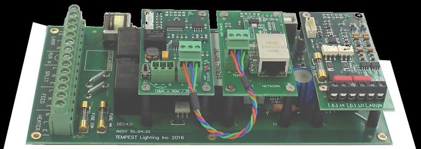
Approvals – China

Blizzard User Manual   6
Introduction
 Thank you for purchasing a Tempest enclosure! We have worked hard to provide you with the very best
 product available for its purpose, and we shall continue to do everything possible to ensure that it works
 well for you for many years to come.
 Please read this manual before starting work!
 In the event of difficulty, please contact your Tempest reseller or Tempest direct:
 info@tempest.biz
 +1 818 787 8984
 We will do everything we can to help you get the very best results from your Tempest enclosure.

 IMPORTANT: Safety Advisories
      •    All installation and rigging work done must where applicable be designed and built in accordance
           with norms and standards of the local authority having jurisdiction of the installation site. It is the
           responsibility of the installer to obtain such approvals as may be required to achieve full
           compliance.
      •    All electrical work must be carried out by a suitably licensed electrical contractor in full
           compliance with local electrical standards.
      •    Lifting: some enclosures and the equipment inside them may be heavy. Use properly rated lifting
           equipment where appropriate and never attempt to carry out work with fewer than the number
           of workers needed to lift safely.
      •    It is the responsibility of the installer to ensure that all local building, safety and electrical codes
           are strictly adhered to in the installation of this enclosure. Tempest Lighting, Inc., its employees
           and agents are in no way responsible for damage arising from failure to follow either the
           instructions in this manual or building, safety and electrical codes prevailing at the installation
           location.
      •    Do not attempt to install or operate the enclosure before fully reading and understanding this
           manual
      •    Never allow anyone who has not read this manual to open the enclosure or perform maintenance
           on the projector within.
      •    Never leave the enclosure unattended when open.
      •    Always make sure all bolts and latches are tight and safety locks are in place after performing any
           form of maintenance on the unit.
      •    Do not open any electrical boxes until power has been shut off to all supply lines to the enclosure
           (including the one powering the projector).
      •    Do not open the enclosure in wet weather.

Blizzard User Manual                                                                                                  7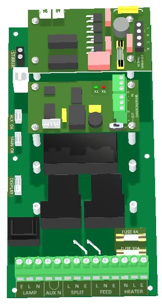
Installation
 Dimensions, Rigging Points, and Maximum Projector Dimensions/Power

                                                                                                     Rigging Points:
                                                                                                     M10-1.5 threaded holes at
                                                                                                     each corner, top and
                                                                                                     bottom.
                                                                                                     Note: 8 x M10x40 stainless
                                                                                                     steel bolts supplied

 Note: Be sure to allow for the length of the lens and for connectors, cables and cable bend radii when calculating dimensions

  Blizzard          A in      A mm          B in        B mm          C in       Cmm           D in        D mm           E in   E mm   W lb   W kg
  52.050L           29          737          28          711          13.5        343           27           686           26    660    59     27
  52.050P           29          737          17          432           27         686           27           686           15    381    64     29
  52.100L           34          864          30          762          14.5        368           32           813           28    711    85     39
  52.100P           34          864          17          432           29         737           32           813           15    381    95     43
  52.125L           34          864          34          864          14.5        368           32           813           32    813    94     43
  52.125P           34          864          17          432           31         787           32           813           15    381    104    47
  52.150L           42         1,067         30          762          16.5        419           40          1,016          28    711    106    48
  52.150P           42         1,067         19          483           31         787           40          1,016          17    432    118    54

 Note: For UST versions, please consult factory

Blizzard User Manual                                                                                                                                  8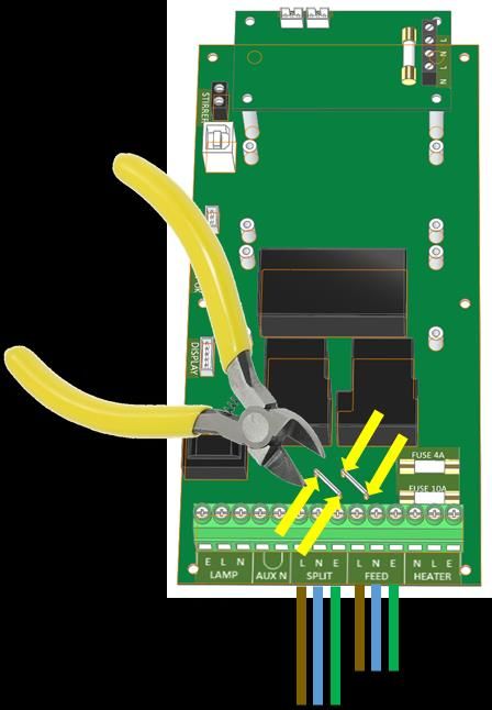
Projector Maximum Dimensions & Power
  Projector Maximum Dimensions/Power
  Blizzard             L in     L mm         W in           W mm         H in         H mm            Watts
  52.050L              22        22.5          9            559          572             229           800
  52.050P              22        22.5          9            559          572             229           800
  52.100L              27        24.5         10            686          622             254          1,250
  52.100P              27        24.5         10            686          622             254          1,250
  52.125L              27        28.5         10            686          724             254          1,250
  52.125P              27        28.5         10            686          724             254          1,250
  52.150L              35        24.5         12            889          622             305          1,800
  52.150P              35        24.5         12            889          622             305          1,800

 Air Clearance                                                                   Allow 1m/3ft for access on
 Observe the minimum clearances shown around your                                at least one side
 enclosure

                                                                                                              50cm/20in

                                                                              75mm/3in

 Snow Clearance
 In areas where snow is likely, make sure the base of the
 enclosure is at least 24” [60cm] above highest potential
 snow drift level.

                                                                  60cm/24in

Blizzard User Manual                                                                                                      9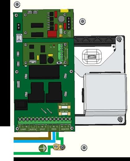
Mounting Bolts
• Each Enclosure must be mounted with FOUR points.
• All mountings must be made using the four M10
threaded holes on the top or bottom of the
enclosure. 6mm
• Use a 6mm hex key to secure the M10 socket cap
screws provided.
• Tempest Lighting recommends the use of stainless
steel mounting hardware. Important:
• Make sure the inlet filter has at least 75mm/3in Sealing Washers –
clearance below. install with rubber side
to enclosure surface
IMPORTANT SAFETY NOTICES
Installer must ensure that all mounting points are secure
and conform to local safety regulations. Tempest Lighting
Inc. accepts no responsibility for damage or injury arising
from inappropriate or unsafe installation.
Stainless Steel
Check that the tip of each mounting bolt is clearly visible
below the nut welded to the internal mounting plates. If Neoprene Rubber
the bolt thread is not visible, remove and replace with a
longer bolt.
Blizzard User Manual 10Mounting Options – Stacking Kit
Blizzard G4 may be stacked up to four units high, using
the 52.SK stacking Kit. You will need the total number of
Blizzards to be stacked, minus one stacking kit(s).
Note: Blizzards must be of the same model to stack in this
way.
52.SK Stacking Kit (set of four, for one enclosure)
Mounting Options – Unistrut Kit Unistrut Rails may be
mounted above or
If mounting positions for the corner bolts are not below
convenient, use the Unistrut Kit (52.UR.050/100/150) to
add two Unistrut rails and Unistrut spring nuts. Bolt top leg to M10
socket each corner
Using the spring nuts, the enclosure may now be Bolt bottom leg
attached at any point along the Unistrut rails. to M10 socket
each corner
Note that the Unistrut Rail kit is required for use of
Blizzard enclosures with the Cyclovator tilt kit. Join top and bottom sections
together with Clevis pins
Mounting Options – Cyclovator
Cyclovator allows you to mount up to two Blizzard 100 or
150 enclosures and tilt them up to 60 degrees either up
(mapping up onto a building or down from a rooftop).
When enclosures are tilted more than about 30 degrees
up or down, use an inlet filter cowl to protect the filter
from rainfall.
55.C2 Cyclovator
52.UR.xxx Unistrut Rail Kit (required)
52.SK Blizzard Stacking Kit (only required to stack two
Blizzards)
52.IC.xx Inlet Cowl
Note that the Unistrut Rail kit is required for use of
Blizzard enclosures with the Cyclovator tilt kit.
Blizzard User Manual 11Mounting Options – Horizontal Pole Bolt Hanger Pan Clamp and tilt adjust to
Kit to top adjustment any 50mm/2” pipe or
Hanger Kit mounting truss beam
Use the Truss Hanger kit to hang any Blizzard enclosure holes with
M10 bolts
from a truss or horizontal pipe up to 50mm (2in)
provided
diameter.
Hanger kits allow XYZ 360° pan, 30° tilt, and 5° roll
adjustment.
52.XH.050L Truss XYZ Kit, Blizzard 050 Landscape
52.XH.050P Truss XYZ Kit, Blizzard 050 Portrait Roll adjustment
52.XH.100L Truss XYZ Kit, Blizzard 100 Landscape bolts both sides
52.XH.100P Truss XYZ Kit, Blizzard 100 Portrait
52.XH.150 Truss XYZ Kit, Blizzard 150
52.XH.150P Truss XYZ Kit, Blizzard 150 Portrait
Mounting Options – Vertical Pole Hanger Bolt Hanger
Kit to top
Kit mounting
Use the Pole Hanger kit to hang any Blizzard 050 or 100 holes with
Clamp and tilt
M10 bolts
enclosure from a vertical pipe up to 50mm (2in) adjust to any
provided
diameter. 50mm/2” pole
We do NOT recommend hanging Blizzard 150 models
from a single vertical pole, due to size and weight
considerations. Use two vertical poles, join together with
a horizontal pipe, and use the Horizontal Pole Hanger kit
above.
Hanger kits allow XYZ 360° pan, 30° tilt, and 5° roll
adjustment.
52.XV.050L Vertical Pole XYZ Kit, Blizzard 050
Landscape
Roll adjustment
52.XV.050P Vertical Pole XYZ Kit, Blizzard 050 bolts both sides
Portrait
52.XV.100L Vertical Pole XYZ Kit, Blizzard 100
Landscape
52.XV.100P Vertical Pole XYZ Kit, Blizzard 100
Portrait
52.XV.150 Vertical Pole XYZ Kit, Blizzard 150
52.XV.150P Vertical Pole XYZ Kit, Blizzard 150
Portrait
Blizzard User Manual 12Mounting Options – Desert Filter Baffle
Use this Baffle to prevent filter damage from wind-blown
sand and dust particles. If these hit the filter at speed
they can quickly ‘sand-blast’ their way through it and
allow fine particles to enter the enclosure.
51.DFB.11 Blizzard 52.050.L.xx/52.100.L.xx
51.DFB.15 Blizzard 52.150.L.xx
For other Blizzard models, consult factory.
Remove the Filter Grille screws, insert baffle below Grille,
and replace.
Make sure there is at least 75mm [3in] clear below the
filter baffle for airflow. Filter Grille
Desert Filter Baffle
Filter Grille Screws
75mm/3in
Wiring the Enclosure
Power Wiring
SAFETY NOTICE: Electrical Standards
All electrical wiring and termination MUST be carried out by Important:
a suitably qualified and/or licensed professional, in Enclosure model numbers ending .US are for use in countries
accordance with electrical and safety norms applicable in the using US and Japanese style electrical systems:
jurisdiction of the installation. Tempest, its employees and
representatives will not be liable for any damage arising 100-120VAC 50/60Hz
from failure to observe this requirement.
Enclosure model numbers ending .IN are for use in countries
using European style electrical systems:
200-230VAC 50/60Hz
Note:
(1) Heaters and fans are rated 115V or 230V,
dependent on electrical standard.
(2) Electronics are autosensing for any voltage 90-
265VAC, 50/60Hz
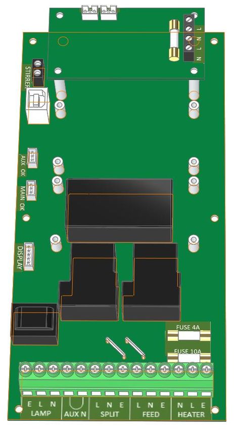
Blizzard User Manual 13Wiring Access
Open the back door, and remove the DEC4 Controller cover
DEC4 Controller
Cover
Fan Control Board
RS485 Comms Board
DEC4 Motherboard
AC Terminal Block
Earth/Ground Terminal
Exhaust Fan Capacitor (positive pressure
option only)
Exhaust Fan
Duplex C13 Power Outlets – use for
projector and aux equipment.
Note:
Your Blizzard enclosure comes with
rewirable C14 plugs to fit these power
outlets.
You MUST connect projector power to
the C13 outlet. If this is not done, the
controller will not sense projector
function and the projector will quickly
overheat.
Blizzard User Manual 14One or Two Power Circuits? 1 1 2
Tempest enclosures may be wired on single or double circuit
supplies. On a single feed, both enclosure and projector are
permanently on. With a split (double) feed supply, you can
switch off the projector when not in use, while the enclosure
continues to protect it 24/7.
Tip: most people use single feed.
Single Feed Split Feed
Single Feed Split feed
• Enclosure and projector are permanently on. • Enclosure power must be permanently ON.
• Enclosure and Projector must be rated for the • Projector power may be switched off.
same voltage. • Enclosure power must be rated for 650 watts.
• Supply must be rated for projector current plus • Projector power must be rated for the projector
150 watts. (see projector manual).
• Supply must be permanently ON. • Projector and enclosure power must be same
voltage.
Blizzard User Manual 15IMPORTANT:
For single feed wiring, no modification to the DEC4 For split feed wiring, use a side cutter to cut both AC links at
Controller motherboard is needed. both ends:
Conduit Entries
Two conduit entry holes are provided, sized for PG21 (US ¾”)
conduit or cable glands. Use one for power and the other for
signal cables.
DO NOT run power and signal cables through the same
conduit.
Conduit Entry Conduit Entry
AC Power Signal
Blizzard User Manual 16Single Feed Power Termination Split Feed Power Termination
• Connect Earth/Ground wire to Ground Terminal • STOP! Did you cut the power links? See above.
• Connect Live and Neutral to the terminals marked FEED • Connect Earth/Ground wire to Ground Terminal
• Connect Enclosure feed to the terminals marked FEED
• Connect Projector feed to the terminals marked SPLIT
Enclosure
AC Supply
Projector
AC Supply
Note: Illustrations show European cable colors:
Brown = Live
Blue = Neutral
Green or green/yellow = Earth/Ground
Blizzard User Manual 17Remote Monitoring Connections
Tempest G4 enclosures optionally support three types of
remote monitoring:
1. Direct via Ethernet, using Tempest TEMP
protocol.
Requires 51.EN Ethernet board
2. Grouped via RS485, using RDM
Requires one 51.485 RS485 board per enclosure
(standard equipment, included)
3. Grouped via RS485, using an Ethernet bridge and
Tempest TEMP protocol
Requires one 51.485 RS485 board per enclosure
(standard equipment, included)
51.EN Ethernet 51.485 RS485 51.485 RS485 51.485 RS485 51.485 RS485
Board Board Board Board 51.EN Ethernet Board
RS485 Daisy Chain
(use CAT5 Cable)
Ethernet LAN Ethernet LAN
Tempest System
Manager
Local PC Remote PC Smartphone Local PC
Note: Tempest System Manager and web-based monitoring are future enhancements that will be announced in due course.
Blizzard User Manual 18RS485 (DMX/RDM) Cable Terminations
DEC4 System Control
Board, with three typical
Daughter Boards:
1. AC Fan Controller
2. Ethernet Bridge
3. RS485 Comms
Loop a shielded twisted pair cable (eg Belden 9841, though
many people now use a CAT5e cable) from the
control/monitoring point, around all enclosures. RS485 Line
Termination
Maximum total cable length is 1,200M (4,000ft). For longer (LT) Switch:
runs and wildly distributed systems, use a DMX/RDM
TERMINATED
splitter (make sure that it supports RDM) and multiple
cable runs.
Use the termination switch to terminate each RS485 cable
run at the last enclosure on each run.
Data + Data - Common Data + Data - Common
DATA OUT DATA IN
Tempest recommends
the JESE SH8 DMX/RDM
Splitter for large or
complex RS485
networks.
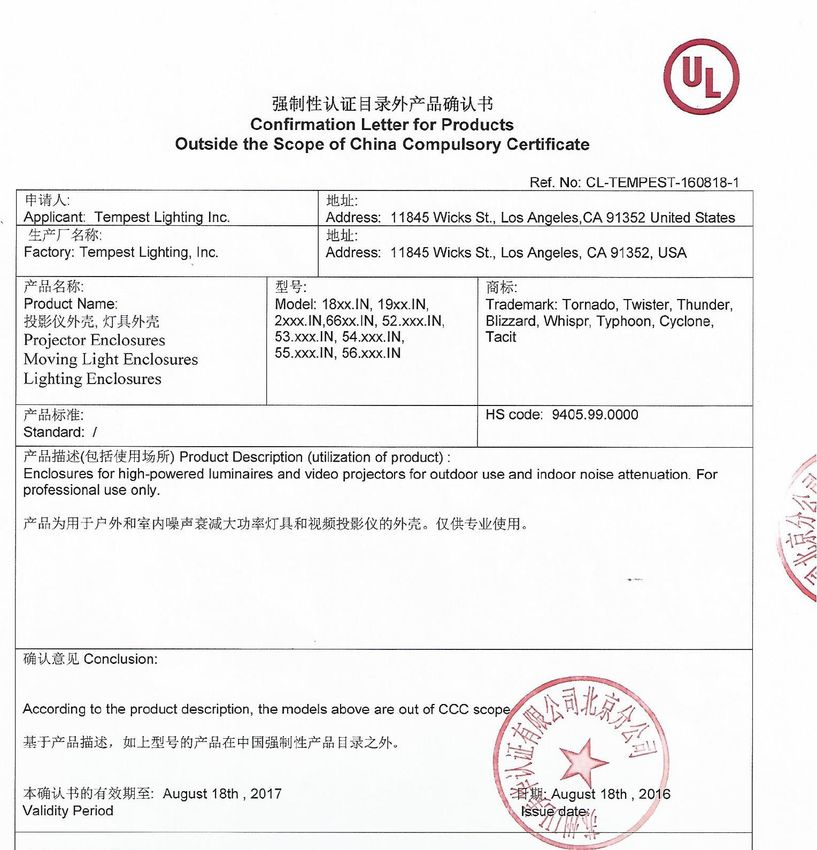
JESE RDM-TRI interface connects to
a PC via USB to monitor and control
a network of Tempest enclosures.
Tempest Item # 2000.195
Blizzard User Manual 19Line Termination Switch Settings 1. DMX/RDM control over RS485: 2. TEMP Control of an enclosure group via Ethernet 3. TEMP Control of a single enclosure via Ethernet Blizzard User Manual 20
DEC4 Ethernet Adapter – 51.EN

                                                51.485                      51.EN
                                     RS485 Comms Board       Ethernet Comms Board

 As a default, DEC4 communicates using DMX512 and RDM, over RS485.

 With the addition of the 51.EN Ethernet board, any DEC4 – or any group of DEC4 boards connected using RS485 – may be
 connected to an Ethernet network – see above.

 Default Configuration
 The bridge module is supplied in DHCP TCP port server configuration, with all traffic on port 3308.
 These settings may be changed with a web browser on port 80 at the DHCP assigned address. Login to
 the home page using ‘admin’ for user name as password.

 The bridges may be discovered with a UDP broadcast on port 1500 and a payload of
 (Hex) 30 31 32 33 34 35 36 37 38 39 30 31 32 33 34 35 36 37 38 39
       30 31 32 33 34 35 36 37 38 39 30 31 32 33 34 35 36 37 38 39
 The bridge will respond from its DHCP address

 Additional Support
 The network IP is developed by Jinan USR, more details and software configuration utilities may be
 found by visiting their web site at https://www.usriot.com

Blizzard User Manual                                                                                                    21
Tempest Equipment Management Protocol TEMP allows you to access status information and set configuration values on DEC3.3 and DEC 4 enclosure controllers, using the 51.EN Ethernet Adapter, over an Ethernet network. Download the Developer Guide at www.tempest.biz/tech_support IMPORTANT: Tempest warrants that, if correctly implemented, TEMP will provide a reliable and accurate method of monitoring Tempest DEC3 and 4 controllers over an Ethernet network. However, the integrator is entirely responsible for the connection between the Ethernet Bridge and the network. Blizzard User Manual 22
Projector Power Control using DMX512
The DEC4 controller includes a 30A 2-pole relay that
protects the enclosed equipment in the event of a serious
high temperature event by cutting off power. In 3-phase
enclosures this is augmented by a 4-pole contactor.
You may use DMX512 (a popular entertainment industry
protocol running on RS485, originally intended to control
lighting system dimmers) to control power to the projector
inside the enclosure. This is very useful in hot locations,
where the projector may be stressed by being held in
standby mode all day under hot sun. By powering the
projector down it will tolerate much higher temperatures
without harm.
Tempest recommends the JESE RDM-TRI interface to
monitor enclosure status in any installation and control the
enclosure power relay in smaller systems.

More complex installations are very likely to include some
kind of show control system that will certainly include DMX
control. This is the preferred method of controlling power
to the projectors.

Blizzard User Manual                                           23
DMX/RDM Network, using JESE RDM-TRI

  The 2000.195 JESE RDM-TRI MK2 passes
  DMX information from a show control
  system to each DEC4 controller.
  Set a DMX address for each controller in the
  range 1-510. See DEC4 section below for
  more information.

Blizzard User Manual                             24
Positive Pressure Fan Control Option
When the Positive Pressure (51.PP) option is ordered, the enclosure fan function is changed.

    •    Normally the enclosure fan(s) will run only when either the projector/luminaire lamp is on, or if the daytime
         temperature in the enclosure exceeds the DEC Upper Temperature setting. At all other times the fan is OFF.

    •    With the Positive Pressure option, when the fan would normally be off, it is instead powered via a capacitor that lowers
         the operating voltage so that the fan continues to run at a low level, maintaining positive pressure in the enclosure and
         preventing harmful contaminants from entering through the exhaust path.

         Fan Control Board              Capacitor                                              Fan

               HI Live terminal ON    LO Live terminal ON
               when:                  when:
               a) Lamp is ON, OR      c) Lamp is OFF, AND
               b) Temperature is      d) Temperature is
                    above Upper           below Upper
                    Temp Setting          Temp Setting

Blizzard User Manual                                                                                                           25
Mounting the Projector
Landscape & Portrait Enclosures – fixed or slide? Tabletop or ceiling?
Projector Fixed or Slide Mounting
Blizzard portrait and landscape enclosures are available
with either fixed or sliding projector mounts.
Fixed or Slide is designated by the 7th digit in the model
Ceiling style
number, eg:
52.100.LF.US Fixed projector mount
52.150.PS.IN Sliding projector mount
Slide Right
Using either Fixed or Slide mounts, you can access the
projector from either side, and also from the back, for
relamping rear-access models without disturbing projector
lineup.
You may configure projector slide mounts to slide out of Slide Left
either the right or left side – see below.
Tabletop style
Ceiling or Tabletop
Blizzard enclosures are configured as standard for tabletop
operation (feet down).
Ceiling (feet up) configuration is a factory option – please
specify when ordering.
Blizzard User Manual 26Projector Slide Direction
Blizzards with the Projector Slide option ship from the
factory configured for tabletop operation, left slide –
shown here…
If that is what you need, skip the next section.
Projector Slide Mount, Tabletop/Left Slide factory default
configuration
Reversing Slide Direction
To switch to Right Slide:
1. Remove the slide latch knobs and flip the slide
latches back, as shown here. This gives access Slide latch knob
to the projector bridge clamp screws
Slide Latch
2. Using a #2 Philips screwdriver, loosen the
projector bridge clamp screws until they are Projector bridge
no longer engaged in the projector bridge clamp screws
clamps.
3. Repeat on the other side of the slide assembly
until all eight screws are free. Projector bridge
clamp
4. Lift out the slide tray assembly, turn it around
so that the slide latches are on the right side,
and replace.
5. Re-engage the eight projector bridge clamp
screws and tighten (use a small screwdriver to
align the projector bridge clamps if you need
to).
6. Replace the slides and slide latch knobs.
Blizzard User Manual 27Mount the Projector – Fixed Mount
Fine for most applications, fixed
mounts hold the projector firmly in
place, while allowing access from
either side and from the back for
alignment, service and lamp changes.
Tabletop Installation
1. Loosen the Bridge Clamp Screws both
sides
2. Slide the projector bridges to align with
projector feet, and re-tighten the bridge
clamp screws.
3. Remove the projector rods nearest you, by
loosening the rod nuts and unscrewing
from the projector bridges.
4. Slide the projector along the projector Projector Bails
bridges so that it is roughly centered in the Projector Beam
enclosure
Projector Bridge
5. Replace the projector rods nearest you.
6. Align the projector, using the projector Projector Rod
feet to adjust tilt and roll. Bridge Clamp Screws
7. When projector alignment is complete,
lower the projector bails and secure firmly
in place by tightening projector rod nuts.
Mount the Projector – Slide Mounts
(1) Slide Mount: slide out the projector tray and
set the projector in place
(2) Adjust the projector bails for a loose fit (you Projector
will adjust and lock down later) Bails
Blizzard User Manual 28(3) Slide the projector back into the enclosure
(4) Secure the projector tray latches and tighten
the latch knobs Projector Tray Latch
Latch Knob
(5) Plug the projector power cable into one of the
IEC C13 outlets provided. THE PROJECTOR
MUST BE POWERED THROUGH THE DEC.
(6) The second outlet is available for any auxiliary
equipment that may be housed inside the
enclosure.
Note that two IEC C14 plugs are provided with the
Blizzard enclosure for your convenience.
IEC C13 Outlets
Blizzard User Manual 29Aligning and Securing the Projector
(1) Use the projector’s feet to adjust projector
alignment.
(2) Tighten Projector bails to secure projector in
place.
(2)
(1)
Blizzard User Manual 30Projector Mount – Portrait
Blizzard Portrait enclosures now come with a universal
projector mounting system that will firmly support any
suitable projector with threaded holes in the projector
base.
A pair of sliding projector bars may be positioned, either
straight or at an angle, so that four mounting points may
be accessed on any projector.
The illustration here shows the portrait slide mount, but
the slide and fixed mounts work the same.
Projector Bar
Portrait Mounting
Frame
Projector mounting
screw and washer
M8 Carriage Bolt
M8 Locknut & Washer
For clarity, the portrait mounting frame is shown outside the enclosure
Blizzard User Manual 31Changing Portrait Orientation
Some projectors may only be used in portrait mode in one
orientation (feet left or feet right).
It is easy to change the orientation, by rotating the portrait
mount assembly (fixed or slide) 180 degrees.
Projector bridge screws
1. Remove the eight projector bridge screws (4 each side)
2. Rotate the projector mount assembly 180°
3. Replace the projector bridge screws
Blizzard User Manual 32Projector Mount – Ultra-Short-Throw
Short-throw projector mounts are fixed, and are not
adjustable. This is to ensure that the beam envelope is Mounting Bolts
correctly maintained within the boundaries of the port
glass.
Like portrait enclosures, Blizzard UST enclosures are
customized to suit the projector specified by the user. Mounting Tray
1. Remove the two safety knobs Safety Knobs
2. Loosen (do not remove) the four mounting bolts
3. Slide the mounting tray forward (away from the
cover hinge) and remove.
4. Attach the projector to the mounting plate, using
the screws provided
5. Lift the mounting plate and projector into the
enclosure base, locate the keyholes on the
mounting plate screw heads, and slide the
projector towards the cover hinge.
6. Tighten all mounting bolts.
7. Insert the two safety knobs and tighten.
Blizzard User Manual 33Digital Enclosure Control
DEC4TM – that’s Digital Enclosure Control, fourth
Typical DEC4
Generation – is the brain of your Tempest enclosure. It will configuration, with
maintain the internal environment in a comfortable Motherboard, fan
temperature and humidity range, and prevent control board and
condensation – the real killer of outdoor equipment. DEC4 RS485 comms
monitors internal and external temperature, humidity and board
lamp current at all times, and uses this information to
control the enclosure’s lamp relay, fan(s) and heater(s). It
can report back over an RS485 network, using the RDM
protocol (Remote Device Management), or connect to
your TCP/IP network for remote monitoring amd
management using Tempest’s TEMP protocol.
Schematic
Blizzard User Manual 34DEC4 Main Functions
Firmware Revision
This manual covers DEC4 Firmware revision 2.03.000 and higher.
To check the Firmware revision, on the User Interface menu, go to Status Display/Firmware.
1. Sense current to projector (lamp on/off) DEC 3.3’s patented GoldilocksTM algorithm uses a combination
2. Record lamp hours of sensors, heaters and fans to maintain a safe operating
3. Monitor temperature and relative humidity temperature and a safe relative humidity level that will not
inside Enclosure allow condensation to take place.
4. Monitor temperature outside enclosure As air is heated it is able to support more moisture without
5. Maintain internal temperature at safe operating condensing, so Goldilocks uses heat to raise the air temperature
level inside the enclosure in the event that relative humidity
6. Maintain relative humidity within safe limits to approaches dewpoint.
prevent condensation
7. Isolate projector in case of unsafe temperature
8. Report status over RS485, RDM, TCP/IP
9. Maintain positive pressure (optional) 24/7 to
prevent ingress of salt air and other
contaminants through the exhaust path
10. Circulates air internally to prevent hot and cold
spots when projector is idle
DEC4 constantly monitors the following parameters:
• Projector/Luminaire current
• Line Voltage
• External Temperature
• Internal Temperature
• Internal Relative Humidity
Factory Settings – Data Modes
In most applications, DEC4 will operate correctly with its
factory default settings, in Basic operating mode.
You do not need to do anything. Please skip to the next
section.
• Standard default temperature and humidity settings
• DMX, RDM and Remote Monitoring disabled
• Best for standalone operation
If your needs are more complex, read on.
Blizzard User Manual 35Hardware Indicators & Fuses
RS 485 Comms Board is
connected and functioning Main Temperature & Fan Board is connected and
correctly (blinking) Humidity Sensor is functioning correctly
connected and functioning (blinking)
External Temperature Sensor(All
is Enclosures)
connected and functioning
Auxiliary Temperature &
(custom applications only)
Humidity Sensor is
connected and functioning
(custom applications only)
RS485 (DMX/RDM) Data
Packets:
Heater Fuse –
Green: Transmit
10A slow-blow Optional Ethernet Board is
Red: Receive
connected and functioning
Daughter Board
Power Fuse – DEC4 Serial Number. Please
4A slow-blow quote in all technical support
enquiries. Fan Fuse – 2A
slow-blow
Blizzard User Manual 36Operating Modes
RDM Only Monitor (Factory Default) • Supports RDM monitoring over RS485 if present
• Supports TEMP monitoring if present
• RDM Status Reporting over RS485
• RDM Configuration – settings may be changed remotely or
at the enclosure user interface.
• No DMX control
RDM+DMX Control • Enclosure functions as a 1-channel DMX device, with
remote control of the lamp relay
o DMX level > 75% enables normal relay operation
(normally ON)
o DMX level < 25% disables normal relay operation
(relay turns OFF)
o This allows you to force a hard reset of the lamp
relay in the event of a projector malfunction
• RDM Status Reporting over RS485
• RDM Configuration – settings may be changed remotely or
at the enclosure user interface.
• Control mode is recommended for show control
applications, but can be risky in live show operation, since
the DMX slot used for the enclosure MUST be kept high to
prevent the lamp relay from opening.
For trained service personnel only
RDM+DMX Service
• Normal operation is suspended and the enclosure
functions as a 3-channel DMX device:
o Lamp Relay (Slot 1)
o Fans (Slot 2)
o Heater (Slot 3)
• RDM Status Reporting over RS485
• RDM Configuration – settings may be changed remotely or
at the enclosure user interface.
• Service mode is ONLY for troubleshooting – DO NOT use
Service mode for normal operation.
Blizzard User Manual 37DEC4 Control Parameters
Temperature and Humidity Ranges
Cooling Fan(s)
Trip Temp
(55-70˚C, Default 60 ˚C)
Low
Upper Temp
(35-50˚C, Default 40 ˚C)
Relative Humidity Trend Temp
(50-90%, (Dynamic)
Default 80%)
IdealTemp (Dynamic, based
on Relative Humidity)
High
LowerTemp
(0-10˚C, Default 0 ˚C)
Heater(s)
Notes:
1 In moving light enclosures the temperature sensor is located in the exhaust airflow. Temperatures
shown may be higher than those around the projector.
2 We recommend using the factory default settings for several weeks or months before making any
changes. In most cases they will not be necessary.
Blizzard User Manual 38Control Interface
LED Indicators
Heater ON (Green) Heater is ON, to maintain lower temperature level or to prevent
condensation
ON (Amber) Enclosure is temporarily outside the Goldilocks zone, and DEC is working to
restore it
Fan ON (Green) Lamp is ON, or Temperature is HIGH and fan is cooling enclosure. Short burst
when lamp off indicates fan moving air to stabilize temp/humidity.
NOTE: Fan LED will not light if no fan is detected
Lamp On ON (Green) Current sensing shows lamp is ON
Lamp hour counter is running
OFF Current sensing shows lamp is OFF
Lamp hour counter is not running
Lamp Relay ON (Green) Lamp relay is closed (normal)
Projector power receptacle is energized
ON (Red) Lamp relay is open due to over-temperature event. Projector power
receptacle is isolated.
Temp FLASHING Temperature is below lower temp setting
(Green)
ON (Green) Temperature is in normal range
ON (Amber) Humidity is above target limit
ON (Red) Temperature is above top setting
FLASHING (Red) Temperature is above Trip level
Projector power is isolated
Data OFF Data not used in present Mode. OR DEC4 is in RDM + DMX Control Mode and
no valid data packet has been detected.
ON (GREEN) Good data packet received.
ON (RED) RDM + DMX Control Mode: Data Fail. A previously good data signal has failed.
Blizzard User Manual 39User Interface LCD Display
The display on the Control display provides additional status
information, depending on the operating mode:
RDM Only Monitor Mode
RDM+DMX Control Mode
RDM+DMX Service Mode
(Alternating DMX Display requires a DMX
signal to be present)
Control Interface Operation
The Control Interface is normally LOCKED.
• To UNLOCK, hold ESC and OK together for 5 seconds.
• You are now in the CONTROL MENU
• Use to scroll up and down the menu.
• Press OK to enter a menu item
• Use to set the item parameter, or to scroll to the
next menu level.
• Use ESC to go BACK, or OK to confirm settings ( ).
• To exit and LOCK, hold ESC for 5 seconds.
Menu will time out and the display will lock after ten
minutes.
Blizzard User Manual 40Control Menu
Set Data Options
SET DATA MODE
From the Front Panel, this menu item allows the user to check (and if necessary change) the Data mode.
RDM Only Monitor DEFAULT Supports RDM or TEMP if connected. No DMX Control.
RDM+DMX Service Service mode – 3 DMX slots, starting with the DMX address set
Important: Please ensure that DEC4 is NOT left in Service Mode.
RDM+DMX Control DMX (set 1 address for lamp relay) plus RDM
SET DATA ADDRESS (in RDM Only Monitor, RDM+DMX Service or RDM+DMX Control Service modes)
Select a DMX starting address in the range 001 to 510
1 – Lamp Relay
In Service Mode an addition two slots are available
2 – Fan Duty Control
3 – Heater Duty Control
Note that the DMX control is designed using a SAFETY pile-on Logic. So the DMX input can only override automatic
settings within safe limits.
SET DATA CURVE
DMX Curves affect the way the fixture relay is controlled in RDM+DMX Control Mode.
DMX levels are shown as %.
Response Curve 1 (default)
DMX level 0-25 Relay disabled (open)
DMX level 26-75 No change to relay status
DMX level 76-100 Relay enabled (normally closed)
Response Curve 2
DMX level 0-19 No change to relay status
DMX level 20-40 Relay disabled (open)
DMX level 41-59 No change to relay status
DMX level 60-80 Relay enabled (normally closed)
DMX level 81-100 No change to relay status
Blizzard User Manual 41SET DATA RESPONSE
DMX Response sets a delay time before DMX Control Mode settings are acted on. Setting a response delay of a few
seconds would prevent unintended fixture relay state changes in the event of a short accidental change in DMX
level.
NOTE: from firmware revision 0.00.100, DEC holds last valid DMX level if DMX is interrupted.
Response Delay Values are:
No Delay (default), 1, 2, 5, 10, 15, 20, 30, 60 seconds.
Set Temp Units
Choose to display temperature values in Celsius or Fahrenheit (default Celsius)
Note that temperature settings must be entered in Celsius.
Set Temp Ranges
Set three temperature trigger points for Bottom, Top and Trip temperatures, in °C.
SET TEMP LOWER (minimum temperature to be maintained)
(default 10°C, permissible range 0-10°C).
SET TEMP UPPER (maximum desired daytime temperature)
(default 45°C, permissible range 35-50°C).
SET TEMP TRIP (temperature at which load will be isolated – see note)
(default 60°C, permissible range 55-70°C).
Note: A thermal emergency is when enclosure ventilation fails with the lamp on, in which case the temperature will
rise very quickly. To avoid nuisance tripping we recommend setting a higher Trip temperature, 60°C or above.
Set Max Humidity
Sets highest desired Relative Humidity: Default 85%, permissible range 80-90%.
Note that, when the projector/luminaire lamp is OFF, the enclosure heaters will switch on to raise the temperature
and lower the risk of condensation. We recommend setting the highest Max Humidity that works in your location, to
avoid unnecessary heater use.
Set Lamp On Point
The lamp current at which DEC detects the projector/luminaire lamp is running. Default is 1 Amp, which allows for
most equipment fans and power supplies to run without changing the air in the enclosure. Lamp on point may be
set in 0.1 Amp increments between 0.2 Amps and 2.0 Amps.
If the enclosure fans never turn off, the Lamp On point is probably set below the standby current draw of the
projector/luminaire. Check the standby current draw on the display and set the Lamp on Current higher.
Reset Lamp Hours
Reset each time you change the lamp in the projector.
Make this a part of your maintenance instructions.
Blizzard User Manual 42Set Fan Function
SET FAN TEST
To test the enclosure fan(s), press [OK]
The enclosure fan will run
The Display Fan LED lights green
DEC Beeps
To stop the fan test, press [ESC]
Status Display
View current status information, using the arrow keys to scroll through:
a) Humidity – relative humidity in %
b) Internal temperature, in degrees C or F
c) External Temperature (custom enclosures with external temperature sensors only)
d) PCB temperature (this will usually be significantly higher than air temperature)
e) Voltage – line Voltage reaching the DEC
f) Current being drawn by projector/light, in Amps
g) Lamp Hours elapsed since last reset
h) Firmware version
i) UID – unique system ID number
Blizzard User Manual 43Safe Mode
In certain circumstances, the DEC User Interface may display the message SAFE
MODE. This can happen if the Humidity sensor stops reporting, or reports an
extreme value, indicating the probability of a sensor error. This situation may
arise either because of a faulty sensor* or in conditions of extremely high
absolute humidity.
In SAFE MODE, the normal Goldilocks operation is temporarily suspended, and
the enclosure works to return the internal environment to a condition from which normal operation may be resumed.
SAFE MODE is SAFE! It indicates that attention may be needed, but not that your equipment is at risk.
* Some sensors shipped before mid-2017 have had a limited operational life in harsher
conditions. Tempest has since developed a new class of capacitive sensor that is far more
resilient, especially in demanding conditions.
✓
The new class of sensors (MG Type) have either:
a) A piece of green tape on the sensor cable
✓
And/or
b) TEMPEST logo on the plastic sensor case
Safe Mode – What to do:
If you see SAFE MODE on your User Interface Display:
1. Check the temperature/humidity sensor:
a. If it does NOT have either a Tempest logo or a piece of green tape on
the cable, contact Tempest for a free-of-charge replacement. If you
have more than one enclosure, we suggest replacing the sensors on ALL
your enclosures.
2. If the sensor has either a Tempest logo or a piece of green tape on the cable,
then: ✓
Blizzard User Manual 44You can also read