SFM-760 CNC MACHINING CENTRE OPERATING MANUAL - NCT Ipari Elektronikai Kft.
←
→
Page content transcription
If your browser does not render page correctly, please read the page content below
SFM-760
                                           CNC MACHINING CENTRE
                                              OPERATING MANUAL

                              SFM-760
           CNC MACHINING CENTRE

                 OPERATING MANUAL

NCT Ipari Elektronikai Kft.       1 / 50            05 October 2020
H-1148 Budapest, Fogarasi út 7.
Phone: +36 1 467 6300
www.nct.hu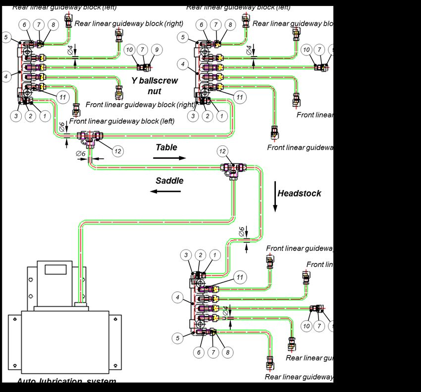
SFM-760
                                                                                             CNC MACHINING CENTRE
                                                                                                OPERATING MANUAL

CONTENTS

1     MACHINE SAFETY GUIDELINES ................................................................................ 5
    1.1    Safety instructions ....................................................................................................... 5
    1.2    Machine hoisting and handling safety ......................................................................... 5
    1.3    Electrical safety ........................................................................................................... 6
      1.3.1      Wiring................................................................................................................... 6
      1.3.2      Grounding connection .......................................................................................... 6
      1.3.3      Environmental conditions .................................................................................... 7
    1.4    Machine safety ............................................................................................................. 7
      1.4.1      Cautions before starting ....................................................................................... 7
      1.4.2      Routine inspection ................................................................................................ 8
      1.4.3      Warming up .......................................................................................................... 8
      1.4.4      Preparation ........................................................................................................... 8
      1.4.5      Operation .............................................................................................................. 9
      1.4.6      Interruption of machining process ...................................................................... 10
      1.4.7      Job completion ................................................................................................... 10
      1.4.8      Maintenance preparation .................................................................................... 10
      1.4.9      Maintenance operation ....................................................................................... 10
      1.4.10 Subsequent jobs after maintenance .................................................................... 11
    1.5    Potential hazard zones of the machine ...................................................................... 11
    1.6    Warning signs ............................................................................................................ 12
    1.7    Illustration of safety positions ................................................................................... 12
    1.8    Machine nameplate .................................................................................................... 13
    1.9    Illustration of operator’s position .............................................................................. 13
2     MACHINE INTRODUCTION ........................................................................................ 14
    2.1    Introduction of machine performance and characteristics ......................................... 14
    2.2    Specification table ..................................................................................................... 14
    2.3    Machine accessories .................................................................................................. 15
      2.3.1      Standard machine accessories ............................................................................ 15
      2.3.2      Special accessories ............................................................................................. 15
    2.4    Machine noise level ................................................................................................... 15
    2.5    Description of main parts .......................................................................................... 16
    2.6    Machine dimension.................................................................................................... 17
  2.7 Dimension, travel and withstanding weight of table ................................................. 18
NCT Ipari Elektronikai Kft.             2 / 50                                      05 October 2020
H-1148 Budapest, Fogarasi út 7.
Phone: +36 1 467 6300
www.nct.hu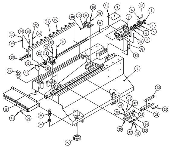
SFM-760
                                                                                    CNC MACHINING CENTRE
                                                                                            OPERATING MANUAL
    2.8    Cutting tool specification........................................................................................... 19
      2.8.1       DIN40 specification ........................................................................................... 19
      2.8.2       Maximum tool specification and weight ............................................................ 20
3     MACHINE HANDLING AND INSTALLATION ......................................................... 21
    3.1    Handling method ....................................................................................................... 21
      3.1.1       Handling of machine in crate ............................................................................. 21
      3.1.2       Handling of machine without a crate ................................................................. 22
    3.2    Preparation before installation ................................................................................... 22
      3.2.1       Requirement of installation space ...................................................................... 22
      3.2.2       Establishment of foundation............................................................................... 23
      3.2.3       Environmental requirement ................................................................................ 24
    3.3    Disassembly and cleaning ......................................................................................... 24
    3.4    Levelness calibration and precision adjustment ........................................................ 24
      3.4.1       Levelness calibration method ............................................................................. 24
      3.4.2       Measure the perpendicularity of spindle centre and table surface ..................... 25
      3.4.3       Adjustment of 3-axis straightness ...................................................................... 25
    3.5    Installation of machine power ................................................................................... 26
    3.6    Connection of hydraulic and pneumatic circuits ....................................................... 26
4     MACHINE MECHANISMS AND ADJUSTMENT ....................................................... 27
    4.1    Headstock mechanism ............................................................................................... 27
      4.1.1       Spindle driving mechanism ................................................................................ 27
      4.1.2       Spindle lock/retract mechanism ......................................................................... 28
    4.2    Feed driving mechanism ............................................................................................ 30
      4.2.1       X axis driving mechanism .................................................................................. 30
      4.2.2       Y axis driving mechanism .................................................................................. 31
      4.2.3       Z axis driving mechanism .................................................................................. 32
    4.3    Magazine mechanism ................................................................................................ 33
      4.3.1       Magazine drive and positioning mechanism ...................................................... 33
      4.3.2       Magazine moving mechanism ............................................................................ 33
5     PNEUMATIC SYSTEM .................................................................................................. 34
    5.1    Pneumatic system diagram ........................................................................................ 34
    5.2    Pneumatic piping diagram ......................................................................................... 35
    5.3    System pressure adjustment....................................................................................... 35
6     LUBRICATION ............................................................................................................... 36
    6.1    Lubrication of spindle bearings ................................................................................. 36
    6.2    Lubrication of slide rail and roller guide bolt ............................................................ 36

NCT Ipari Elektronikai Kft.                                  3 / 50                                          05 October 2020
H-1148 Budapest, Fogarasi út 7.
Phone: +36 1 467 6300
www.nct.hu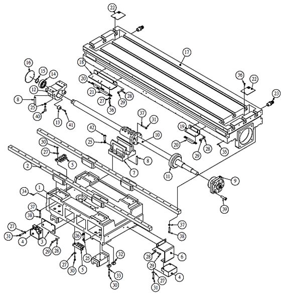
SFM-760
                                                                               CNC MACHINING CENTRE
                                                                                       OPERATING MANUAL
    6.3     Lubrication of guide bolt bearings............................................................................. 36
    6.4     Lubrication of other parts .......................................................................................... 37
      6.4.1        Lubrication of ATC roller-type guideway ......................................................... 37
      6.4.2        Lubrication of counterweight chain and chain wheel bearings .......................... 38
      6.4.3        Lubrication of boosting cylinder ........................................................................ 38
    6.5     Lubrication position ................................................................................................... 39
    6.6     Concentrative lubrication system diagram ................................................................ 40
    6.7     Table of characteristics of oil on all parts.................................................................. 41
7     MAINTENANCE AND SERVICING ............................................................................. 42
    7.1     Daily maintenance ..................................................................................................... 42
    7.2     Weekly maintenance .................................................................................................. 42
    7.3     Semi-annual maintenance .......................................................................................... 42
    7.4     Annual maintenance .................................................................................................. 42
8     PART LIST ...................................................................................................................... 43
    8.1     Base ........................................................................................................................... 43
    8.2     Column ...................................................................................................................... 45
    8.3     Table .......................................................................................................................... 47
    8.4     Headstock .................................................................................................................. 49

NCT Ipari Elektronikai Kft.                                       4 / 50                                             05 October 2020
H-1148 Budapest, Fogarasi út 7.
Phone: +36 1 467 6300
www.nct.hu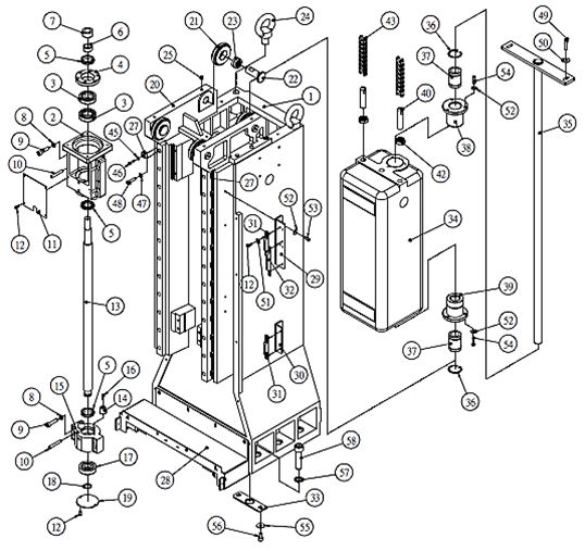
SFM-760
                                                                 CNC MACHINING CENTRE
                                                                    OPERATING MANUAL
1     MACHINE SAFETY GUIDELINES

1.1   Safety instructions

WARNING!
Please do not try to operate the machine until you have read and understood all descriptions,
regulations and safety caution items described in this manual. This machine is designed with
various safety devices to protect the operator and maintenance personnel, and to avoid acci-
dental injury and damage to the machine and equipment. However, operator and maintenance
personnel should not rely completely on such safety precautions. For the sake of operational
safety, retain this manual for reference.

1.2   Machine hoisting and handling safety

A forklift is recommended for handling. To handle this machine, the cutting fluid box should
be dismantled. Avoid moving the fulcrum, which may destroy mechanical structure or alter its
precision. In case site restrictions require use of a crane, ensure proper balance and protection
is obtained to avoid shaking and collision.

Safety caution items
1. The safety loading capacity of all handling machines or equipment should be higher than
   the weight of the machine (including crane, forklift and hoisting equipment). In case of
   doubt, inquire with the manufacturer of the handling equipment. Never handle equipment
   by yourself without adequate knowledge, or the handling equipment or machine may be
   damaged, and personnel may be injured. (For related weight of the machine, please refer
   to 2.2; for handling method, please refer to 3.1.)
2. When a crane is used, to avoid damage to the machine, use the special hoist designed spe-
   cifically for this machine and the correct way. Do not use a nonconforming hoist as it may
   result in damage to the handling equipment or machine, or even personnel casualties.
3. Whatever method is used to hoist or handle the machine, when the machine is hoisted
   5 cm above ground level, make sure to carefully check if the machine is balanced. Make
   sure the machine is not moved in an unbalanced state, or it may cause casualties or dam-
   age.
4. When the machine is hoisted or lowered, pay attention to its moving speed. If the speed is
   too fast it will result in unpredictable swinging or collision, or the hoisted machine may
   drop off in an unbalanced status, causing casualties or damage.
5. When the machine is being hoisted or handled, prohibit personnel from clinging to
   the periphery or topside of the machine, and prohibit personnel clinging to the hoist and
   cable, to avoid casualties.
6. When the machine is being hoisted or handled, prohibit personnel and vehicles from en-
   tering the downside of the machine to avoid any accident.
7. To operate hoisting and handling equipment, actual operation shall be executed only by
   qualified personnel who have received professional training and are certified by relevant
   authorities. Prohibit operation by personnel who are not familiar with equipment condi-
   tions to avoid an accident.
8. Before the machine is hoisted or handled, make sure to remove all objects around the ma-
   chine. Any obstacles on the walking path should be removed. People should keep away
   from the machine before the machine can be hoisted or handled to avoid damage or inju-
   ry.
NCT Ipari Elektronikai Kft.                  5 / 50                            05 October 2020
H-1148 Budapest, Fogarasi út 7.
Phone: +36 1 467 6300
www.nct.hu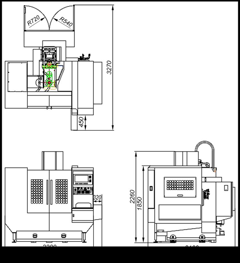
SFM-760
CNC MACHINING CENTRE
OPERATING MANUAL
1.3 Electrical safety
To ensure safe operation of NC machine, note the following.
1.3.1 Wiring
1. Please use electric conductors having the same, or better, rated power as pre-set.
2. Please do not connect the power cord of this machine to a power source with excessive
voltage drop.
3. Please do not connect the power cord of this machine to a power cable of equipment that
produces noise, such as: welding machine and high frequency quenching machine.
4. Cables connected with machine power source must be installed by a qualified engineer.
1.3.2 Grounding connection
Use impedance grounding wire having a section area more than 14mm2 and an impedance of
less than 100 Ω. Meanwhile, the dimension of grounding wire shall be more than AWG NO.5
and SWG NO.6 Normally an NC machine shall be individually connected to an independent
grounding rod. If independent grounding could not be provided for the machine, please con-
nect to ground according to the following conditions:
1. Connect an individual conductor to other grounding terminals to prevent resulting
grounding current entering NC machine control and causing a serious accident in case of
failure to peripheral devices.
2. A cement steel rod can provide an impedance of less than 100 Ω to ground, so it is often
used as a grounding device. When a steel rod cement bar is used for grounding purposes,
please connect it according to the following description:
3. For a welding machine and high frequency quenching machine that can easily cause
noise, please do not use the same grounding cement steel rod or grounding terminal.
4. Please use terminals that can withstand the rated power of this machine, which can be
grounded simultaneously.
5. In case separated grounding wires must be used, make sure to shorten their length.
6. Please execute actual measuring to check grounding impedance; when one independent
device is connected to grounding rod, its impedance should be less than 100 Ω.
7. Required independent grounding:
For several equipment items with independent connection to grounding terminals,
please make grounding connection as illustrated in Fig. 1, the grounding impedance is
less than 100 Ω.
Joint grounding: For several equipment items with parallel connection to grounding
terminals, please make grounding connection as illustrated in Fig. 2, the grounding im-
pedance is 100 Ω.
Prohibit serial connection of several equipment items to grounding terminals, as shown
in Fig. 3.
NCT Ipari Elektronikai Kft. 6 / 50 05 October 2020
H-1148 Budapest, Fogarasi út 7.
Phone: +36 1 467 6300
www.nct.hu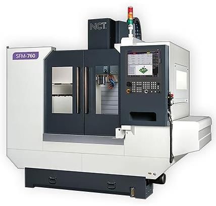
SFM-760
CNC MACHINING CENTRE
OPERATING MANUAL
1.3.3 Environmental conditions
Machine installation shall satisfy the following conditions, but these conditions may change
after a certain period of time or with seasonal changes.
1. Power voltage: 85%~110% of rated voltage
2. Power frequency: ±1 HZ of rated frequency
3. Ambient temperature: 0 °C~45 °C(32 °F~113 °F)
4. Relative humidity: Less than 90% temperature change range, and shall not result in mois-
ture condensation.
5. Environment: Avoid dust and corrosive gases containing acid and alkaline, do not install
NC machine in an environment with irregular vibration, and do not expose NC machine
to direct sunshine or heated light rays. All of the above will affect the service life and pre-
cision of the machine.
6. In case the above conditions are not available, please contact us immediately.
1.4 Machine safety
1.4.1 Cautions before starting
POSSIBLE DANGER!
Before using the machine, check if any cable and wire insulation is damaged. Make sure to
confirm such conditions, or it will cause current leak and electrocution.
WARNING!
1. Make sure to fully understand every operational performance and procedure described in
the operational manual and instructions.
2. Make sure to wear safety clothing and oil-resistant safety boots, and wear goggles with
side covers and other protective gear.
3. Close operation box, electric control box door and protective cover.
CAUTION!
1. Cables laid on the floor must be installed with protective devices, to avoid contact with
iron rust and resultant “short-circuiting”.
2. The factory should be provided with sufficient power supply to all facilities, to enable
smooth operation of the machine.
3. After the new machine is unpacked but before initial operation, or if has not been used for
an extended period of time, each moving part should be cleaned and lubricated with man-
ually operated lubricating oil, and the lubricating oil pump shall be started several times
until the lubricating oil seeps into every moving part.
4. For the viscosity, brand and applicable grades of lubricating oil, please refer to the name-
plate or 6.7 in this manual.
5. Check all switches and operating rods are in smooth and satisfactory operating condition.
6. To turn on power, please follow the procedure below: Turn on factory power switch
Turn on no-fuse switch of main circuit to ON or 1 (the power lamp lights on) Press the
green ON power knob on NC power operation panel Turn on emergency switch
Turn on exterior air pressure system switch.
7. To use hydraulic system and collective lubrication, make sure to check the oil level in the
oil tank, and timely top up oil level to specified oil level mark.
NCT Ipari Elektronikai Kft. 7 / 50 05 October 2020
H-1148 Budapest, Fogarasi út 7.
Phone: +36 1 467 6300
www.nct.hu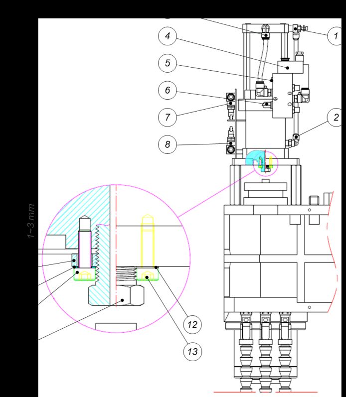
SFM-760
                                                                CNC MACHINING CENTRE
                                                                     OPERATING MANUAL
8. Check the level of cutting fluid. When fluid level is lower than the lower limit, please top
   up cutting fluid to its upper limit.

1.4.2 Routine inspection
WARNING!
Before inspecting the machine, make sure to turn off power and reconfirm the power is turned
off. Do not proceed with inspection and adjustment of the machine until you have put up
warning signs at conspicuous places to prevent your fingers from being squeezed or cut off.

CAUTION!
1. Properly inspect and read the pressure gauge indicator meter and see if the pressure set-
   ting is appropriate.
2. Check motor and other parts for irregular noise.
3. Check if lubrication on moving parts and rolling parts is appropriate.

1.4.3 Warming up
After it is laid unused for an extended period of time, if the machine is started and begins to
be used immediately without warming up, moving parts will be burned, resulting in oil leaks.
The reason is the machine is suddenly subjected to heat expansion which destroys the preci-
sion of the machine. After warming up, the precision in machining parts is more stable. To
prevent such a problem, a new machine or a machine idle for an extended period of time
should be warmed up before daily operation. To warm up, first operate the machine at a low
speed, and then accelerate its operation to a higher speed.

CAUTION!
1. To restart the machine after it has stopped, please manually and slowly return all axes to
   their original points for confirmation.
2. To warm up in an automatic operation mode, you can refer to the machining conditions of
   the work piece and set an appropriate spindle rpm, as well as feeding speed for X, Y and
   Z axes, and continuously operate for 10~20 minutes.
3. Warm-up procedure shall include every movement of the machine, to enable checking if
   the machine operation is normal, even when executed in automatic operation mode.
4. Before warming up the machine in automatic operation mode, make sure to reset all mov-
   ing parts to their original points at a slow speed, and make sure if program commands are
   correct. When all moving parts are executed according to programmed commands, make
   sure there is no interference, or it will result in collision and damage to the machine.

1.4.4 Preparation
WARNING!
1. Do not put cutting tools or other objects on top of the spindle box, work table or chute
   protective cover to avoid an accident and to ensure safety to operating personnel and
   neighbourhood working personnel.
2. Damaged and defective cutting tools will damage the work piece, so they should be re-
   placed before machining operation.
3. Make sure to provide appropriate lighting equipment in the working area, to facilitate
   safety and inspection.
NCT Ipari Elektronikai Kft.               8 / 50                          05 October 2020
H-1148 Budapest, Fogarasi út 7.
Phone: +36 1 467 6300
www.nct.hu
SFM-760
                                                                 CNC MACHINING CENTRE
                                                                      OPERATING MANUAL
4. Cutting tools and other objects to be positioned at the periphery of machine should be
   positioned at their appropriate locations, to keep the walking path clean and clear.
5. Selection of cutting tools shall be made in consideration of whether they comply with
   the maximum limits pre-set in the item of cutting tools in the specification of this machine
   (which shall be used for reference) and if they will interfere with the work piece and op-
   tional accessories (fourth axis, etc.). Safety distances shall be considered when deciding
   the distances of cutter reserve, cutter feed, and cutter replacement. To set cutting tool
   specification, please refer to 2.8.
CAUTION!
1. After a cutting tool is installed, test lathing is required to make sure there is no problem
   with the tool.
2. Make sure the dimension of work piece conforms to machine specification, to avoid inter-
   ference or collision in its range of travel.

1.4.5 Operation
WARNING!
1. Do not wear gloves when operating the machine or it may result in accident or danger.
2. The operator should not allow their hair hangs to loosely, or it may result in accident or
    danger.
3. Bailey ropes, steel cables, hoists or lifting machines shall have sufficient strength to carry
    the load.
4. Only the operator who has received professional training may operate the forklift, crane,
    hoist and other similar equipment.
5. Pay special attention when operating the forklift, crane or similar equipment. In operation,
    make sure to prevent collision and damage to the machine and its surrounding environ-
    ment.
6. To move a larger work piece, two or more persons shall be needed to move it together, to
    avoid danger.
7. In machining operation, the work piece must be securely and properly clamped.
8. Make sure the machine has stopped properly before trying to adjust the area from cutting
    liquid spray nozzle to cutter point.
9. Do not hand touch rotating work piece or spindle, or other rotating machine parts.
10. Do not remove the safety protective cover of machine without permission.
11. Do not use hands to remove iron scraps on cutting tool. Make sure to use a brush for that
    purpose, to avoid cutting injury.
12. Make sure the machine has stopped properly before trying to remove the cutting tool.
13. When working in a dusty environment, the operator should wear protective gear. When
    the machine is machining graphite work piece or a work piece with powdered dusts, the
    operator must wear a protective mask or turn on the dust collector, because working
    in a dusty environment can result in occupational injury to personnel.
CAUTION!
1. In machining process, do not open the protective doors of all machine parts.
2. In heavy machining process, make sure to prevent excessive accumulation of iron scraps,
   which may cause rising temperature and result in a fire inside the machine.

NCT Ipari Elektronikai Kft.                  9 / 50                            05 October 2020
H-1148 Budapest, Fogarasi út 7.
Phone: +36 1 467 6300
www.nct.hu
SFM-760
CNC MACHINING CENTRE
OPERATING MANUAL
1.4.6 Interruption of machining process
WARNING!
When completing a job and trying to leave the machine, make sure to turn off power switches
on operational panel and non-fuse switch of main power supply.
1.4.7 Job completion
CAUTION!
1. After a job is completed, make sure to remove iron scraps, clean the machine, wipe doors
and windows and chute protective cover and peripheral equipment, and apply engine oil
on machine bench surface, chute protective cover, and other moving parts to prevent cor-
rosion due to moisture in the air.
2. Before cleaning the machine or equipment, please turn off power switch on operational
panel, the no-fuse switch of main circuit and the exclusive switch for this machine
in the factory, and hang up a warning sign UNDER MAINTENANCE – DO NOT
TURN ON POWER, to avoid accidental injury to personnel.
3. Reset all axes of the machine to middle points of their cycle, and reset the machine to its
original conditions.
4. Check cutting fluid, hydraulic oil and lubricating oil for their extent of deterioration and
emulsification. If they are deteriorated or emulsified, please replace with new.
5. Check the liquid level mark of cutting fluid, hydraulic oil and lubricating oil. Refill if
the level is low.
6. Clean cutting fluid, hydraulic oil and lubricating oil filters.
7. Before finishing work and leaving the machine, make sure to turn off power switch on
operational panel, no-fuse switch of main circuit and the special switch for this machine
in the factory.
1.4.8 Maintenance preparation
CAUTION!
1. Do not execute maintenance without instructions from the chief executive.
2. Carefully read and fully understand related safety precautions and preventive measures
described in the manual.
3. Before maintenance, prepare replacement parts, and consumables (pads, oil seals,
O-rings, bearings, oil, grease, etc.)
4. Before maintenance, carefully read the maintenance manual and fully understand
the meaning therein, and familiarize yourself with the correct maintenance procedure, es-
tablish maintenance records, and make proper maintenance according to normal mainte-
nance schedule.
1.4.9 Maintenance operation
POINTS OF DANGER!
1. Before maintenance, make sure to turn off the power source in the factory, the special
switch for this machine and no-fuse switch of machine’s main circuit, and put up signs of
UNDER MAINTENANCE – DO NOT TURN ON POWER at the switches or at con-
NCT Ipari Elektronikai Kft. 10 / 50 05 October 2020
H-1148 Budapest, Fogarasi út 7.
Phone: +36 1 467 6300
www.nct.huSFM-760
CNC MACHINING CENTRE
OPERATING MANUAL
spicuous places, to prevent other people from turning on the switches and causing acci-
dental harm.
2. Turning on machine power supply, and any maintenance or servicing is dangerous.
As a general rule, make sure to turn off the non-fuse switch of the main circuit before at-
tempting maintenance.
WARNING!
1. Maintenance of electrical devices should be executed by professionals only. Do not main-
tain the machine yourself, you should contact concerned personnel. Do not service
the machine without permission, so as to avoid danger.
2. Absolutely prohibit moving or modifying over-travel limits and linking mechanism, in-
cluding mechanism-related parts.
3. When working at an elevated place, do not stand on top of the machine or plate work.
Make sure to use pedal steps or a ladder to ensure safety.
Use only electrical parts, fuses, cables and wires that are made by qualified manufacturers.
1.4.10 Subsequent jobs after maintenance
WARNING!
1. After maintenance, disassembling tools, removed and replaced parts, all types of fasteners
and instruments should be collected, assorted and returned to their original positions.
2. After maintenance, make sure to clean the working environment and keep the ground
surface clean and tidy, to provide a comfortable and safe working environment.
3. After maintenance, the operator should keep the replaced parts and waste oil products
away from the machine and at appropriate locations in the factory to ensure safety.
CAUTION!
1. Maintenance personnel should check if machine operation is safe.
2. Maintenance and inspection data should be filed in records for future reference.
3. In case maintenance personnel cannot proceed in case of irregularity found during
maintenance and inspection, immediately contact our factory or dealer to conduct mainte-
nance and inspection. Do not try to disassemble the machine for maintenance when they
do not understand the circumstances.
1.5 Potential hazard zones of the machine
The user should clearly know that all rotating or moving mechanisms, especially moving
at a high speed, in incorrect operation or through careless behaviour (such as unintentionally
or unknowingly touching of a knob or key, etc.) may result in unwanted activation of the ma-
chine and possible danger. Therefore, when the machine was designed, all moving or rotating
mechanisms were installed inside safety protective hoods to avoid direct contact with person-
nel. However, they could not avoid unexpected dangerous behaviour by the operator. There-
fore, in addition to correct operational knowledge, the operator and maintenance personnel
should gain correct understanding of potential hazardous zones of this machine, and be alert
for possible danger, to avoid unnecessary accident and injury.
NCT Ipari Elektronikai Kft. 11 / 50 05 October 2020
H-1148 Budapest, Fogarasi út 7.
Phone: +36 1 467 6300
www.nct.huSFM-760
CNC MACHINING CENTRE
OPERATING MANUAL
The arrow signs and circular signs in the following diagram indicate high-speed
movement and rotating mechanism. The operator and maintenance personnel should ensure
their operation is within the range of movement.
1.6 Warning signs
1.7 Illustration of safety positions
1. Emergency stop knob 2. Front door safety switch
NCT Ipari Elektronikai Kft. 12 / 50 05 October 2020
H-1148 Budapest, Fogarasi út 7.
Phone: +36 1 467 6300
www.nct.huSFM-760
CNC MACHINING CENTRE
OPERATING MANUAL
1.8 Machine nameplate
1.9 Illustration of operator’s position
NCT Ipari Elektronikai Kft. 13 / 50 05 October 2020
H-1148 Budapest, Fogarasi út 7.
Phone: +36 1 467 6300
www.nct.huSFM-760
CNC MACHINING CENTRE
OPERATING MANUAL
2 MACHINE INTRODUCTION
2.1 Introduction of machine performance and characteristics
1. This model is high-speed operation equipment, with its main structure comprising of
a base, saddle, table, column, headstock, driving members, operation box, CNC control,
lubricating system, pneumatic system, safety protective hood, cutting conveyor equip-
ment, dust collecting equipment, etc. Its main performance is targeted at machining steel,
iron, copper, aluminium and such metal and alloy materials, and is not suitable for ma-
chining that in the process will produce powdered dusts, corrosive liquid, gas and magne-
sium metal, or it may result in unpredictable environmental pollution and even injury or
casualty to personnel.
2. This machine is a machining tool equipped with CNC and servo control, capable of mak-
ing proper machining preparations and delivery of operation to the control for automatic
production, to enhance working efficiency and upgrade the safety level for operators. But
that does not represent absolute safety in actual operation. Therefore, when operating this
machine, make sure to read the correct operation described in the manual, and pay atten-
tion to all cautionary signs, warning signs, danger signs and messages. Do not try to oper-
ate without due authorization. The following is a detailed description of the operation of
all components of this machine.
2.2 Specification table
X/Y/Z axis travel [mm] 760/400/400
Track type Linear guideway
Table dimension [mm] 1270×305
T channel dimensions (number of channels×size×distance) [mm] 3×16×102
Distance between spindle and table [mm] 102 ~ 502
Centre of spindle to rail surface of column [mm] 432
Workload [kg] 200
3-axis fast feed [m · min–1] 12/12/12
Max. feed rate [m · min–1] 1~10
Magazine capacity [pieces] 16, umbrella
Max. cutter size (with neighbour cutter) [mm] 100
Max. cutter size (no neighbour cutter) [mm] 150
Max. cutter length [mm] 200
Single cutter maximum cutter weight [kg] 6
Spindle taper BT40
Spindle rpm [min–1] 6000
HPB VM100S-54-40-15-08 spindle motor power [kW] 5,73
Spindle transmission Belt type
Spindle lubrication Grease
Power main [kVA] 12
Machine height (approx.) [mm] 2400
Land area occupied (approx.) [mm] 2510×2170
Machine weight (approx.) [kg] 2400
NCT Ipari Elektronikai Kft. 14 / 50 05 October 2020
H-1148 Budapest, Fogarasi út 7.
Phone: +36 1 467 6300
www.nct.huSFM-760
CNC MACHINING CENTRE
OPERATING MANUAL
2.3 Machine accessories
2.3.1 Standard machine accessories
1. Rigid tapping
2. RS-232 interface
3. Automatic power outage
4. Automatic lubrication system
5. LED work lamp
6. Program end work lamp
7. Electric box heat exchanger
8. Full-cover panelling / wire controlled hand wheel
9. Level adjustment screw pads
10. Tools and tool kit box
11. Operation manual
2.3.2 Special accessories
1. Spindle oil cooler
2. High pressure water scour for chip removal
3. Electric box refrigerator box
4. Coolant through spindle centre
5. Screw type chip conveyor
6. Oil skimmer
7. Chain type chip conveyor
8. Oil through tool holder
9. Scraper type conveyor
10. Oil-mist lubrication pump
11. Fourth axis
12. DRO
13. Transformer
2.4 Machine noise level
Noise output level, according to ISO 7960
A Weighted sound power level, Lward, dB re 1pW Empty load In operation
A weighted sound power level at operator position,
1pAd,dB re 20 μpa
66 82
Judgment of figures is based on ISO 3746 test regulations.
This cited table is for emission grade, and is not required by safety working grade. In case
there is a relationship between injection grade and exposure grade, do not use this table to
judge whether additional protective measures are required. Factors that actually affect expo-
sure grade of work piece include the time when the noise was sustained (e.g., level in the vi-
cinity of the machine). Exposure grade may vary in different countries. This information may
allow the user to better assess hazards and risks.
NCT Ipari Elektronikai Kft. 15 / 50 05 October 2020
H-1148 Budapest, Fogarasi út 7.
Phone: +36 1 467 6300
www.nct.huSFM-760
CNC MACHINING CENTRE
OPERATING MANUAL
2.5 Description of main parts
1 Base
2 Saddle
3 Table
4 Headstock
5 Column
6 Magazine
7 Hood plating
8 Operation box
9 Electric box
NCT Ipari Elektronikai Kft. 16 / 50 05 October 2020
H-1148 Budapest, Fogarasi út 7.
Phone: +36 1 467 6300
www.nct.huSFM-760
CNC MACHINING CENTRE
OPERATING MANUAL
2.6 Machine dimension
NCT Ipari Elektronikai Kft. 17 / 50 05 October 2020
H-1148 Budapest, Fogarasi út 7.
Phone: +36 1 467 6300
www.nct.huSFM-760
CNC MACHINING CENTRE
OPERATING MANUAL
2.7 Dimension, travel and withstanding weight of table
1. Maximum load capacity of table: 200 kg
2. Dimensions of the table as follows:
NCT Ipari Elektronikai Kft. 18 / 50 05 October 2020
H-1148 Budapest, Fogarasi út 7.
Phone: +36 1 467 6300
www.nct.huSFM-760
CNC MACHINING CENTRE
OPERATING MANUAL
2.8 Cutting tool specification
The cutting tool specification suitable for this machine is: DIN40
2.8.1 DIN40 specification
NCT Ipari Elektronikai Kft. 19 / 50 05 October 2020
H-1148 Budapest, Fogarasi út 7.
Phone: +36 1 467 6300
www.nct.huSFM-760
CNC MACHINING CENTRE
OPERATING MANUAL
2.8.2 Maximum tool specification and weight
In tool selection, make sure it is the maximum value pre-set in the cutting tool items
in the specification of this machine; this will serve as reference. Cutting tools shall be selected
within such reference values. Consider whether it will interfere with the work piece or option-
al accessories (such as the fourth axis, etc.) Tool retract, feed and change distance shall con-
sider safety distance.
Maximum tool weight [kg] 6 kg
A: Maximum tool length [mm] 200
B: Maximum tool diameter [mm] 100 (full tools)
150 (neighbour empty)
NCT Ipari Elektronikai Kft. 20 / 50 05 October 2020
H-1148 Budapest, Fogarasi út 7.
Phone: +36 1 467 6300
www.nct.huSFM-760
CNC MACHINING CENTRE
OPERATING MANUAL
3 MACHINE HANDLING AND INSTALLATION
3.1 Handling method
3.1.1 Handling of machine in crate
Use a forklift to handle a machine packed in crate
1. Since the weight of the machine in crate
is approximately 2.5 metric tons, in case
a forklift is used the safety carrying load
capacity of the forklift shall be more than
3 metric tons to avoid accident.
2. During handling, be mindful of any per-
sonnel or obstacles in the path of traffic.
In case there are personnel and obstacles,
first evacuate the personnel and remove
obstacles to avoid impact and ensure
safety of personnel and the machine.
3. In case a forklift is used, the forks should be adjusted to their proper positions. Make sure
the centre of gravity of crated machine should be at the loading centre of the forklift, to
avoid tilting and accident.
4. When the forklift lifts up the crated machine, watch the lifted height. Do not lift it too
high or it may swing due to too high a centre of gravity and result in an accident.
5. In case vision is obstructed when handling the crated machine, recommended movement
is to reverse the forklift. There should be a co-worker on the side to give instructions and
ensure safety. The driving speed of the forklift should be as slow as possible.
Using a crane to handle a crated machine
1. Since the weight of a crated machine is approximately
2.5 metric tons, if a crane is used, the safety loading capaci-
ty of the crane should be more than 3 metric tons or more to
avoid an accident.
2. The steel cable or chain of the crane shall be capable of
carrying a weight of more than 3 metric tons, or the steel
cable or chain may have tensile fatigue or other problems
that may result in the machine dropping items during han-
dling process, resulting in an accident.
3. When a crane is used, its hanging hooks and steel cable
should be adjusted to proper positions. Be careful the centre
of gravity of the crated machine should be placed at the
loading centre of the crane, to avoid tilting and harm to per-
sonnel and the machine.
4. During handling, be mindful of any personnel or obstacle in the path of traffic. In case
there are personnel and obstacles, evacuate the personnel and remove the obstacles to
avoid impact and ensure safety of personnel and the machine.
5. The traveling speed of the crane should not be too fast. There shall be people beside
the crane to ensure safety.
NCT Ipari Elektronikai Kft. 21 / 50 05 October 2020
H-1148 Budapest, Fogarasi út 7.
Phone: +36 1 467 6300
www.nct.huSFM-760
CNC MACHINING CENTRE
OPERATING MANUAL
3.1.2 Handling of machine without a crate
Using a forklift to handle a machine without a crate
1. The weight of a non-crated machine is approximately 2.4 metric tons. If a forklift is used
to handle it, the safety loading capacity of the forklift shall be more than 3 metric tons to
avoid an accident.
2. During handling, be mindful of any personnel or obstacle in the path of traffic. In case
there are personnel and obstacles, evacuate the personnel and remove the obstacles to
avoid impact and ensure safety of personnel and the machine.
3. In case a forklift is used to handle, the forks should be adjusted to their proper positions.
Make sure the centre of gravity of crated machine should be at the loading centre of
the forklift, to avoid tilting and accident.
4. When the forks lift up the machine, make sure of the lifted height. Do not lift it too high,
or it may swing due to too high a centre of gravity, and result in an accident.
5. In case vision is obstructed when handling the machine, recommended movement is to
reverse the forklift. There should be a co-worker on the side to give instructions and en-
sure safety. The driving speed of the forklift should be as slow as possible.
3.2 Preparation before installation
10 days before installation, the site and handling path should be arranged. Meanwhile, to en-
sure machine precision and service life, make sure to consider the impact of environment on
the machine, and take appropriate measures to make improvement or prevention. In case it is
impossible to satisfy the following “installation space”, “installation foundation” and “envi-
ronmental requirements”, please adopt proper measures for improvement and contact our fac-
tory or dealer, so that technicians can handle the case instead. Do not attempt to handle the
case without knowing the circumstances, or it may result in damage to personnel or the ma-
chine.
3.2.1 Requirement of installation space
1. The exterior dimensions of the machine may vary due to different equipment. For stand-
ard dimensions, refer to 2.6 of this manual.
2. To avoid failure to install the machine because of insufficient space after the machine is
delivered to the place of installation. Make sure to measure the space where the machine
shall be installed and see if the space of handling path is satisfactory to standards 30 days
before the machine is scheduled to arrive at the place of installation. If not, make sure to
notify our factory or dealer as soon as possible. They shall try to provide recommenda-
tions and consultation service to settle any doubts concerning space requirements for ma-
chine installation.
NCT Ipari Elektronikai Kft. 22 / 50 05 October 2020
H-1148 Budapest, Fogarasi út 7.
Phone: +36 1 467 6300
www.nct.huSFM-760
CNC MACHINING CENTRE
OPERATING MANUAL
3.2.2 Establishment of foundation
To maintain machine precision on a permanent basis, we suggest you make sound and proper
work for the foundation according to the standards for machine foundations. If foundation
work is not robust, it will cause the machine to vibrate and affect its precision and quality.
The machine foundation must be built 10 days before the machine is scheduled to arrive at the
place of installation, otherwise if the foundation is not yet set when the machine is delivered
to the place of installation, installation of the machine will be delayed. Working procedure as
follows:
1. First, refer to the dimensions in the foundation drawing and excavate foundation chan-
nels, then pave its bottom layer with pebbles to solidify the foundation.
2. Grout concrete, making sure spaces for foundation bolt channels are reserved according to
the foundation drawing.
3. After the concrete is set, spread flat plates onto the reserved foundation bolt channels.
4. Place the machine on the plate, and insert L-shape foundation bolts from bottom to top
through the flat plate, level adjusting block and adjust bolts, fixing washers and nuts.
Check precision level of the machine, and tighten check nuts and fasten level adjusting
bolts.
5. Gout concrete in the foundation bolt channels, making sure the concrete surface is on the
same level as the foundation concrete. Wait seven to ten days until the concrete has com-
pletely set, then you may calibrate the level precision of the machine.
Foundation layout plan
NCT Ipari Elektronikai Kft. 23 / 50 05 October 2020
H-1148 Budapest, Fogarasi út 7.
Phone: +36 1 467 6300
www.nct.huSFM-760
CNC MACHINING CENTRE
OPERATING MANUAL
3.2.3 Environmental requirement
Machine installation shall satisfy the following conditions. However, such conditions may
change after a certain period of time or with seasonal changes.
1. Power voltage: rated voltage: 85%~110%.
2. Power frequency: ±1 HZ of rated frequency
3. Ambient temperature: 0 °C~ 45 °C(32 °F~ 113 °F)
4. Relative humidity: No moisture condensation shall occur in a range of temperature
change of less than 90%.
5. Environment: Avoid excessive dust and corrosive gases containing acid, alkaline, etc. Do
not install NC machine in an environment with irregular vibration. Do not expose NC
machine to direct sunshine or heated light rays, because the above factors will affect the
service life and precision of the machine.
6. In case the above conditions could not be satisfied, contact us immediately.
3.3 Disassembly and cleaning
1. During the machine handling process, to prevent its moving parts from being displaced,
the moving parts are fastened to devices sprayed with red paint and tied with labels.
Those fastening devices must be removed after handling of the machine is completed and
before use, so that the machine can operate normally.
2. Before ex-factory delivery, all parts of the machine have been sprayed with anti-rust oil or
such anti-corrosion treatment. After the machine has arrived in place, please wipe
the contact surfaces of all moving parts, but do not wipe off the anti-rust compound on
sliding and rotating surfaces that are not in contact with others.
3. Prohibit the use of compressed air to remove dust and extraneous matter from the ma-
chine, or they may be blown into the clearances between sliding and rotating surfaces in
contact, resulting in jamming or damage to contact surfaces.
4. Prohibit the use of organic solvents to wipe any parts of the machine.
5. Remove desiccants which have been put inside the machine, or inside the electric box or
operation box before ex-factory shipment of the machine.
3.4 Levelness calibration and precision adjustment
Levelness and precision of the machine should be adjusted very carefully, because initial in-
stallation shall have a significant impact on the precision and service life of the machine.
3.4.1 Levelness calibration method
1. Move the table and saddle to the middle of all cycles, and put
two pieces of 200 mm level gauge (spirit level) in the centre of
the table, respectively pointing to X and Y directions.
2. Adjust the foundation level adjusting bolt (M32) to control
the level of table. Adjust T1, T3 and T5 to calibrate X and
Y axis level. Low point first adjusted higher. T2 and T4 are
level auxiliary calibrating bolts. In such an order, adjust until
the level precision in X and Y axis direction is less than
0.02/M.
NCT Ipari Elektronikai Kft. 24 / 50 05 October 2020
H-1148 Budapest, Fogarasi út 7.
Phone: +36 1 467 6300
www.nct.huSFM-760
CNC MACHINING CENTRE
OPERATING MANUAL
Tighten (M32) check nut, make sure the level gauge remains at its original precision, then
tighten M16 nut. Finally, reconfirm the level gauge maintains its original precision and
the level precision calibration is completed.
3.4.2 Measure the perpendicularity of spindle centre and table surface
1. Fasten a micrometer on the surface of spindle’ nose end.
2. Adjust the pointer needle of micrometer and the distance of spindle to 150~160 m/m
(diameter about 300).
3. Move Z axis until the pointer needle of micrometer comes to contact table surface.
4. Slowly turn the spindle, and measure its maximum figure. If it is beyond tolerance, mi-
nute adjustment may be made by turning the adjusting bolt of the foundation. Such preci-
sion shall be directionally specified; the figure in Y and Z directions closer to the operator
shall be less than 90°.
3.4.3 Adjustment of 3-axis straightness
1. Use a micrometer and a granite square master or triangular master.
2. Put granite square master or triangular master on work table surface.
3. Fix the micrometer on the surface of spindle nose end, with the micrometer slightly in
touch with the granite.
4. Move X, Y and Z axes to adjust and reset the front and rear ends of the square meter or
triangular master, then move the measured axes (Y, Y and Z) to measure their maximum
figures; in case they are beyond tolerance, inspection is required.
NCT Ipari Elektronikai Kft. 25 / 50 05 October 2020
H-1148 Budapest, Fogarasi út 7.
Phone: +36 1 467 6300
www.nct.huSFM-760
CNC MACHINING CENTRE
OPERATING MANUAL
3.5 Installation of machine power
3.6 Connection of hydraulic and pneumatic circuits
NCT Ipari Elektronikai Kft. 26 / 50 05 October 2020
H-1148 Budapest, Fogarasi út 7.
Phone: +36 1 467 6300
www.nct.huSFM-760
CNC MACHINING CENTRE
OPERATING MANUAL
4 MACHINE MECHANISMS AND ADJUSTMENT
4.1 Headstock mechanism
4.1.1 Spindle driving mechanism
Belt type: Spindle is driven by spindle motor as its power source, with a belt to drive the spin-
dle to rotate.
Adjustment of spindle belt tension
After extended use, spindle belt will loosen. Please timely check and adjust it as follows:
1. Loosen four fixing bolts on motor seat.
2. Use the bolts to adjust to appropriate belt tension.
3. Tighten four fixing bolts on motor seat.
Recommended belt adjusting deflection
and bending force
Tension Deformation
New belt 29,4 N 3 mm
After use 24,5 N 3 mm
Use tension gauge to measure the cen-
tral position of belt.
NCT Ipari Elektronikai Kft. 27 / 50 05 October 2020
H-1148 Budapest, Fogarasi út 7.
Phone: +36 1 467 6300
www.nct.huSFM-760
CNC MACHINING CENTRE
OPERATING MANUAL
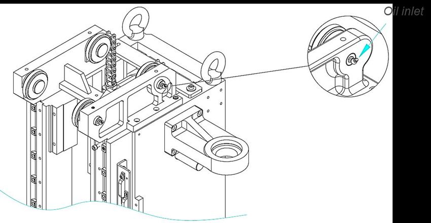
4.1.2 Spindle lock/retract mechanism
Spindle tool is released by a lock/retract tool that boosts the cylinder at the rear end of
the spindle, pushing the draw bar to release the tool handle; with an air spray device cleaning
the tool sheath taper and tool handle. Spindle tool is tightened by spring force of the disc pull-
ing up the draw bar, thereby driving the tool clamp claw fastening on the boosting bolt at rear
end of the tool, causing the tool to be fastened onto the taper of the nose end of the spindle.
Adjustment of boost
1. No 13 After loosening two M5 fixing
screws, No 14, adjust bolt to adjust
the boost. This bolt is turned anticlock-
wise to have more boost, or clockwise to
have less boost. After adjustment
the boost is 0.6~0.7mm. After adjust-
ment, No 13, tighten again two M5 fix-
ing screws, making sure to tighten diag-
onally one by one, and to not tighten
a single screw at one time. After it is
completed, adjust the 2~3 mm gap
marked on screw fixing plate, No 11, to
fasten the adjusting bolt, No 14.
2. No 1, change tool blow air adjust valve,
adjust tool change air blow pressure
at 2~3 bar, to ensure the tools are clean
after changing the tools, and maintain
machining precision.
3. Nos 7 and 8 are lock/retract detect
switches, properly adjust the detect posi-
tions; in case of incorrect adjustment,
jammed or drawn tool will result, and
cause irregularity in tool change. After
adjustment, use spring washer to fix and
avoid loosening due to vibration.
NCT Ipari Elektronikai Kft. 28 / 50 05 October 2020
H-1148 Budapest, Fogarasi út 7.
Phone: +36 1 467 6300
www.nct.huSFM-760
CNC MACHINING CENTRE
OPERATING MANUAL
Code Description Specification Note
1 Retract air blow vent volume adjust valve Throttle valve ∅8 mm_1/4” –
2 Spindle retract air blow inlet L type fast connector ∅8 mm_1/4” –
3 Tool unclamp inlet L type fast connector ∅10 mm_1/4”
4 Clamp/unclamp control solenoid 3/8” 5-opening 2-place single control MVSC-300-4E1
5 Compulsory boost knob – –
6 Tool clamp inlet Copper 90o double exterior thread con- –
nector 3/8”×1/4”
7 Clamp detect switch – –
8 Unclamp detect switch – –
9 Oil cup – –
10 Wind source inlet L type fast connector ∅10 mm_3/8” –
11 Adjusting screw fixing plate – –
12 M5 spring washer – –
13 Boost fixing screw M5×0,8 –
14 Boost adjusting bolt M16×1,5 counter clockwise –
NCT Ipari Elektronikai Kft. 29 / 50 05 October 2020
H-1148 Budapest, Fogarasi út 7.
Phone: +36 1 467 6300
www.nct.huSFM-760
CNC MACHINING CENTRE
OPERATING MANUAL
4.2 Feed driving mechanism
4.2.1 X axis driving mechanism
AC servo motor is designed as the source of force for X axis driving mechanism. The cou-
pling directly drives the ball screw to rotate and thereby drives the table, to move the table in
X direction on the roller-type linear guideway on the saddle. Before ex-factory shipment, this
machine has been
subjected to rigorous tests. Please do not adjust by yourself unless absolutely necessary.
Leave adjustment to our professional technicians so as not to affect machine precision and
damage the bearings.
NCT Ipari Elektronikai Kft. 30 / 50 05 October 2020
H-1148 Budapest, Fogarasi út 7.
Phone: +36 1 467 6300
www.nct.huSFM-760
CNC MACHINING CENTRE
OPERATING MANUAL
4.2.2 Y axis driving mechanism
AC servo motor is designed as the source of force for Y axis driving mechanism. The cou-
pling directly drives the ball screw to rotate and thereby drives the saddle, to move the saddle
in Y direction on the roller-type linear guideway on the base. Before ex-factory shipment, this
machine has been
subjected to rigorous tests. Do not adjust by yourself unless absolutely necessary. Leave ad-
justment to our professional technicians so as not to affect machine precision and damage the
bearings.
NCT Ipari Elektronikai Kft. 31 / 50 05 October 2020
H-1148 Budapest, Fogarasi út 7.
Phone: +36 1 467 6300
www.nct.huSFM-760
CNC MACHINING CENTRE
OPERATING MANUAL
4.2.3 Z axis driving mechanism
AC servo motor is designed as the source of force for Z axis driving mechanism. The cou-
pling directly drives the ball screw to rotate and thereby drives the headstock, to move
the headstock in Z direction on the roller-type linear guideway on the column. Before ex-
factory shipment, this machine has been subjected to rigorous tests. Do not adjust by yourself
unless absolutely necessary. Leave adjustment to our professional technicians so as not to
affect machine precision and damage the bearings.
NCT Ipari Elektronikai Kft. 32 / 50 05 October 2020
H-1148 Budapest, Fogarasi út 7.
Phone: +36 1 467 6300
www.nct.huSFM-760
CNC MACHINING CENTRE
OPERATING MANUAL
4.3 Magazine mechanism
4.3.1 Magazine drive and positioning mechanism
1. Forward and backward travel of this magazine is driven by a pneumatic cylinder;
the pneumatic cylinder serves to push it.
2. Magazine rotating mechanism: motor drives double driving keys to flip the Geneva
wheel, and speed reducing gear drives the tool disc to rotate for tool selection.
3. This machine adopts two-way latest tool selection control to shorten the tool selection
time.
4. Magazine tool selection and positioning is achieved by detection by Geneva wheel and
proximity switch.
4.3.2 Magazine moving mechanism
Magazine moving mechanism travels forward and backward by way of the pneumatic cylin-
der directly driving the magazine, with air pressure as the source of driving force. The maga-
zine moves to and fro on the track. To change tools, push the magazine to the tool changing
position in spindle direction. After tools are changed, the magazine is drawn back to its origi-
nal position, and its position is detected by the micro switch.
NCT Ipari Elektronikai Kft. 33 / 50 05 October 2020
H-1148 Budapest, Fogarasi út 7.
Phone: +36 1 467 6300
www.nct.huYou can also read