Using DOCSIS to Meet the Larger BW Demand of the 2020 Decade and Beyond - Tom Cloonan, Ayham Al-Banna, Frank O'Keefe
←
→
Page content transcription
If your browser does not render page correctly, please read the page content below
Using DOCSIS to Meet the Larger BW Demand of
the 2020 Decade and Beyond
Tom Cloonan, Ayham Al-Banna, Frank O’Keefe
Contents

                                       Abstract . . . . . . . . . . . . . . . . . . . . . . . . . . . . . . . . . . . . . . . . . . . . . . . . . . . . . . . . . . . . . . . . . . . . . .   3
                                       Introduction . . . . . . . . . . . . . . . . . . . . . . . . . . . . . . . . . . . . . . . . . . . . . . . . . . . . . . . . . . . . . . . . . .       3
                                             Traffic Engineering and Motivation . . . . . . . . . . . . . . . . . . . . . . . . . . . . . . . . . . . . . . . . . .                           3
                                       Possible Paths Supporting the Future Capacity Needs of Broadband . . . . . . . . . .                                                                   4
                                             Overview. . . . . . . . . . . . . . . . . . . . . . . . . . . . . . . . . . . . . . . . . . . . . . . . . . . . . . . . . . . . . . . . . . .    4
                                             The First Path (Revolutionary Change). . . . . . . . . . . . . . . . . . . . . . . . . . . . . . . . . . . . . . . .                             5
                                             The Second Path (Evolutionary Change) . . . . . . . . . . . . . . . . . . . . . . . . . . . . . . . . . . . . .                                  5
                                       Extended Spectrum DOCSIS . . . . . . . . . . . . . . . . . . . . . . . . . . . . . . . . . . . . . . . . . . . . . . . . . .                           6
                                             Basic Idea Behind Extended Spectrum DOCSIS. . . . . . . . . . . . . . . . . . . . . . . . . . . . . . .                                          6
                                             HFC Plant Topics for Extended Spectrum DOCSIS Systems. . . . . . . . . . . . . . . . . . . .                                                     7
                                             Tap Topics for Extended Spectrum DOCSIS Systems . . . . . . . . . . . . . . . . . . . . . . . . . .                                              9
                                             Optical Beat Interference Topics for Extended Spectrum DOCSIS Systems. . . . . .                                                                 9
                                             Distributed Access Architecture Topics for Extended Spectrum
                                       		         DOCSIS Systems . . . . . . . . . . . . . . . . . . . . . . . . . . . . . . . . . . . . . . . . . . . . . . . . . . . . . . . . 10
                                             Spectrum Topics for Extended Spectrum DOCSIS Systems. . . . . . . . . . . . . . . . . . . . 10
                                             Full Duplex and Half Duplex Topics for Extended Spectrum
                                       		         DOCSIS Systems . . . . . . . . . . . . . . . . . . . . . . . . . . . . . . . . . . . . . . . . . . . . . . . . . . . . . . . . 12
                                             OFDM/OFDMA Topics for Extended Spectrum DOCSIS Systems. . . . . . . . . . . . . . 15
                                       Extended Spectrum DOCSIS Coaxial Simulation Results. . . . . . . . . . . . . . . . . . . . . . . . 15
                                             Extended-Spectrum System Capacity for FTTLA Systems . . . . . . . . . . . . . . . . . . . . 17
                                             Extended-Spectrum System Capacity for FTTT Systems . . . . . . . . . . . . . . . . . . . . . . 17
                                             The Effect of Total Transmitted Power on Extended Spectrum Capacity. . . . . . . . 19
                                             The Effect of Source SNR and CPE Noise Figure on Extended
                                       		         Spectrum Capacity. . . . . . . . . . . . . . . . . . . . . . . . . . . . . . . . . . . . . . . . . . . . . . . . . . . . . . . 20
                                       The Effect of RF Tilt on Extended Spectrum Capacity. . . . . . . . . . . . . . . . . . . . . . . . . . . . . 22
                                       Extended Spectrum DOCSIS Experimental Results . . . . . . . . . . . . . . . . . . . . . . . . . . . . 23
                                       Conclusions. . . . . . . . . . . . . . . . . . . . . . . . . . . . . . . . . . . . . . . . . . . . . . . . . . . . . . . . . . . . . . . . . . . 24
                                       Related Readings. . . . . . . . . . . . . . . . . . . . . . . . . . . . . . . . . . . . . . . . . . . . . . . . . . . . . . . . . . . . . 25

2 Using DOCSIS to Meet the Larger BW Demand of the 2020 Decade and Beyond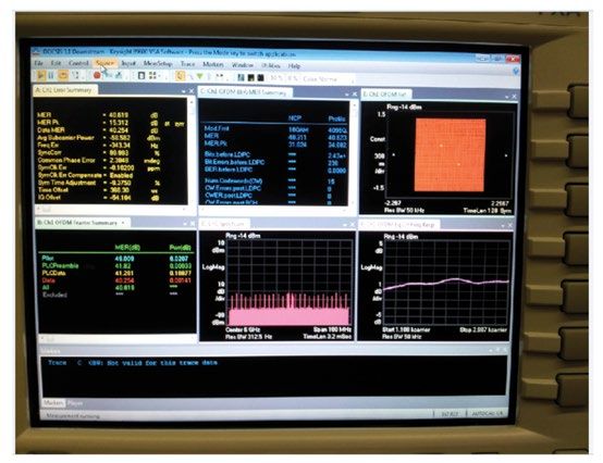
Abstract
          Forward-looking predictions on future bandwidth demand indicate that the 10-15 Gbps BW capacities of DOCSIS
          3.1 systems may become limiting by the middle of the 2020 decade. This paper will explore novel ideas that propose
          to extend the DOCSIS 3.1 specifications to permit DOCSIS to support subscriber Bandwidth (BW) needs into the
          2030 decade and beyond. The paper will study BW trends, discussing the details of different options for augmenting
          plant BW capacity. The paper will then describe extended-spectrum DOCSIS, showing that it offers many advantages
          to Multiple System Operators (MSOs), including backward compatibility, investment protection, the avoidance of
          large capital costs, elimination of unnecessary operational challenges, and the utilization of the full capacity of their
          existing Hybrid Fiber-Coaxial (HFC) networks.

          The paper will analyze the performance of HFC networks at higher frequencies and propose a gradual migration
          plan that increases the BW from 10 Gbps to (perhaps) 200+ Gbps. The paper will also analyze the effect of multiple
          parameters such as attenuation, signal source tilt, multiple modulation profiles, variable bit loading, and type and
          length of the hard / drop coaxial cables. The paper will conclude by describing a potential evolutionary path that the
          MSOs may follow as they migrate from DOCSIS 3.1 systems to extended-spectrum DOCSIS systems.

          Introduction

          Traffic Engineering and Motivation

          The Cable Industry is now a recognized leader in the delivery of Last-Mile Services to residential subscribers, and it
          is continually expanding its access to business subscribers. The offered services include Video, Voice, and Broadband
          Data services. While the Cable network started out as a simple coaxial infrastructure optimized for the delivery of
          Analog Video, it has evolved into a powerful Hybrid Fiber-Coaxial (HFC) system over the years to support these many
          varied service types.

          The HFC network has proven time and time again that it is an extremely flexible and robust infrastructure that
          can be morphed to accommodate the unique and continually-changing needs of the subscribers and the different
          services. The addition of amplifiers for longer reach was the beginning of this evolution. That was followed by
          spectral expansions to deliver more TV channels. That was then followed by the addition of fiber to further increase
          reach and reduce the effects of electrical interference. The addition of DOCSIS for Voice and Broadband service was
          another powerful modification. Fiber Deep solutions (based on continual node-splits) have carried the network to its
          current state of existence. In the near future, DOCSIS 3.1 augmentations will expand the spectrum and the spectral
          efficiency of the HFC network to support (perhaps) ~10 Gbps Downstream bandwidth capacity and ~2 Gbps
          Upstream bandwidth capacity on a 1.2 GHz plant with a 204 MHz high-split. Discussions are now underway on the
          topics of Full-Duplex DOCSIS that may permit even higher Upstream bandwidth capacities in the near future. Future
          DOCSIS 3.1 expansions to 1.7 GHz may even permit the HFC network to even support ~15+ Gbps of Downstream
          bandwidth capacity.

          Is the 15 Gbps bandwidth capacity of DOCSIS 3.1 the last change that we will make to the HFC network? Is
          the bandwidth capacity offered by DOCSIS 3.1 (in its current form) adequate for the long-haul into the future?
          To answer these questions, we must explore the likely bandwidth requirements that may be placed on the HFC
          network over the next fifteen years. Voice and Video will always consume a reasonable percentage of the HFC
          spectrum. Voice bandwidth requirements for small service groups of the future will be essentially negligible, but
          video bandwidth for those service groups will become quite large as Ultra-High Definition (UHD) feeds become
          more prevalent. For example, if an MSO plans to deliver 500 programs of UHD Video (with (say) 12 Mbps per
          stream) using switched techniques (SDV or Multicast IP Video) to a futuristic Service Group with ~100 subscribers

3 Using DOCSIS to Meet the Larger BW Demand of the 2020 Decade and Beyond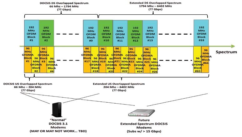
(50% active, 3 viewers per active home), then these programs might require ~1.4 Gbps of bandwidth capacity.
          In addition, nDVR/VoD viewing from those ~100 subscribers might require an additional 300 Mbps of bandwidth
          capacity (assuming a 30% usage rate). Thus, video feeds to a small, futuristic 100-subscriber Service Group might
          consume ~1.7 Gbps of bandwidth capacity.

                                                          Figure 1: DS BW vs. Year

          Broadband Services (with expected 50% annual growth rates) will also add an ever-growing demand of additional
          bandwidth capacity needs on top of that Video bandwidth capacity. If the Broadband growth rates are extrapolated
          into the future, the curve in Figure 1 is obtained (for a typical 100-subscriber Service Group of the future).

          The red, dashed horizontal line shows the 10-15 Gbps capacity level that may become a limiting factor in the future.
          This figure illustrates that the DOCSIS 3.1 bandwidth capacity limits may permit Broadband data to be supported on
          DOCSIS 3.1 networks until the mid-2020’s.

          But what follows that? Will the bandwidth capacity that subscribers require in the distant future (the late 2020’s and
          beyond) be satisfied by the 10-15 Gbps offered by DOCSIS (as currently defined)? Apparently not.

          Thus, is it time to look at replacement technologies for DOCSIS? Are there any other solutions to the problem of
          limited bandwidth capacity? These are all important questions that will be addressed in this paper.

          Possible Paths Supporting the Future Capacity Needs of Broadband

          Overview

          It is clear that the Cable Industry must plan for some changes if it is going to continue to support the growing
          Broadband capacity needs of subscribers into the deep future. There are two possible paths that could be followed.

          The first path requires the MSO to invest heavily in a new Last-Mile Delivery infrastructure (and technology) that will
          ultimately replace the HFC network. The second path requires the MSO to continue incremental investments in the
          existing Last-Mile Delivery infrastructure and to find new ways to augment the capacity of the legacy HFC network.

4 Using DOCSIS to Meet the Larger BW Demand of the 2020 Decade and Beyond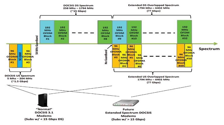
The First Path (Revolutionary Change)

    MSOs who choose the first path are likely to build a parallel network over the top of their existing network, giving them
    the opportunity to operate both networks in parallel during the transition period. In fact, many MSOs that follow this
    path may actually keep their legacy HFC network operational for decades to help provided extra bandwidth and to help
    support legacy in-home CPE equipment.

    MSOs have many technology options to select from as they look at potential new delivery infrastructures. The list includes
    (but is not limited to) RF over Glass, Hybrid PON, EPON, GPON, and point-to-point Ethernet [EMME]. Interestingly, all of
    these technologies utilize a Fiber-To-The-Home (FTTH) architecture to eliminate the high-frequency attenuation that occurs
    within coaxial systems. While fiber does greatly reduce the attenuation issues, it does introduce other issues (such as
    dispersion) that must also be accounted for.

    FTTH systems are oftentimes assumed to be the desired end-state technology for Last-Mile Delivery systems, and that
    is probably a correct assumption. However, FTTH systems do tend to have one undesirable trait (for many MSOs). In
    particular, FTTH systems can be expensive to initially install and deploy. Estimates vary and depend on many conditions,
    but the cost of installing new fiber over the last 150’ to a typical home and equipping that home with a new ONU
    equipment can fall in the $500 – $1000 range [EMME]. For many MSOs, the additional expense associated with adding
    a new FTTH connection to a home is not desirable and therefore other approaches must also be considered. A very
    promising approach is outlined in the following section.

    The Second Path (Evolutionary Change)

    The second path that MSOs can choose to follow as they expand their per-subscriber bandwidth capacity is a path that
    attempts to augment the capacity of the existing Last-Mile Delivery infrastructure. In a sense, this approach is not new.
    This is the “business-as-usual” approach that has been applied to the HFC network continuously for the past sixty years. It
    uses new technologies as they become available to continually push more and more bandwidth through the HFC system.

    One of the key points that became apparent to the authors within another study [CLO1] is that MSOs are barely
    beginning to scratch the surface of the full potential bandwidth capacity of the HFC infrastructure. Both the fibers and
    the coaxial legs within the existing HFC network can carry much more bandwidth capacity than they are transporting
    today. So it begs the question—should MSOs build a costly FTTH system to replace their existing HFC network when
    smaller investments and augmentations within the existing HFC network can be made to permit them to deliver much
    more bandwidth capacity to their subscribers in the future. For some MSOs, this evolutionary approach may be more
    desirable than the revolutionary approach required by FTTH deployments.

    It is interesting to note that telcos were facing a similar situation in the mid-1990’s. Their existing twisted-pair connections
    to homes were viewed by many as having reached the end of their realistic lifespan, and many actually proposed FTTH
    as a technology to replace the twisted-pair connections. While some telcos did deploy FTTH solution in some areas,
    many more telcos actually found that it was more cost-effective to continue to use the existing 100-year-old twisted-pair
    technology. They found innovative ways to boost its performance level with DSL and (ultimately) G.Fast technologies.
    These approaches have permitted the telcos to extend the life-span of their twisted-pair copper by at least 20 years, and
    twisted-pair is still used as a Last-Mile Broadband infrastructure by the Telco industry today [CLO1].

    MSOs have an opportunity to follow a similar path that could greatly extend the lifespan of their existing HFC plant. In
    particular, they can decide to extend the spectrum of their DOCSIS network well beyond the Downstream RF upper band
    edge of 1.794 GHz that is specified in the current DOCSIS 3.1 specification [DPHY].

5 Using DOCSIS to Meet the Larger BW Demand of the 2020 Decade and Beyond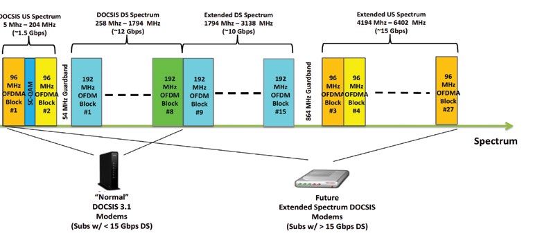
Figure 2: Extended Spectrum DOCSIS in Spectrum Offering ~50 Gbps in ~6 GHz

          Extended Spectrum DOCSIS

          Basic Idea Behind Extended Spectrum DOCSIS

          One approach focusing on the second path defined above is an approach known as “Extended Spectrum DOCSIS.”
          The idea is quite simple. Rather than change out the entire HFC plant for a new technology to increase their
          bandwidth capacity levels, MSOs can instead choose to continue to use the HFC plant by extending the spectrum that
          supports DOCSIS 3.1 OFDM blocks beyond the 1.794 GHz limit that is specified in the DOCSIS 3.1 specification today
          (see Figure 2). The top frequency in the Extended Spectrum might be 3 GHz or 6 GHz or 12 GHz or higher. The actual
          top-end frequency and bandwidth capacity that can be utilized will undoubtedly be function of the manner in which
          the signals are delivered to the home. (Several different techniques will be outlined below).

          The idea is based on a simple application of the well-known Shannon-Hartley Theorem from the field of Information
          Theory [SHAN]. In particular, the Shannon-Hartley formula states that:

                   C = B*log2(1+S/N)          (1)

          Where C is the maximum channel bandwidth capacity (in bits per second), B is the channel frequency bandwidth
          (in Hertz), S is the average signal power level across the bandwidth (in Watts), and N is the average noise power
          level across the bandwidth (in Watts). In essence, the formula states that the channel capacity is the product of two
          terms. The first term is the bandwidth (B) of the channel—a wider bandwidth produces a higher channel capacity.
          The second term is log2(1+S/N), which is closely related to the signal-to-noise ratio on the channel. One illustrative
          interpretation of the formula is that 1GHz of frequency bandwidth, with ~31dB SNR, has theoretical channel capacity
          of 10 Gbps!

          If we assume that the signal power (S) launched into a channel remains fixed (due to transmitter power limitations
          or due to FCC power level limitations), then the expansion of channel bandwidth capacity (C) depends only on the B
          value and the N value within the above formula. For simplicity, we will assume that the noise power spectral density
          is a constant value across the entire channel bandwidth, given by N0 (in Watts per Hz). Thus, the noise power (N) is
          given by the simple relationship:

                   N = N0*B.     (2)

6 Using DOCSIS to Meet the Larger BW Demand of the 2020 Decade and Beyond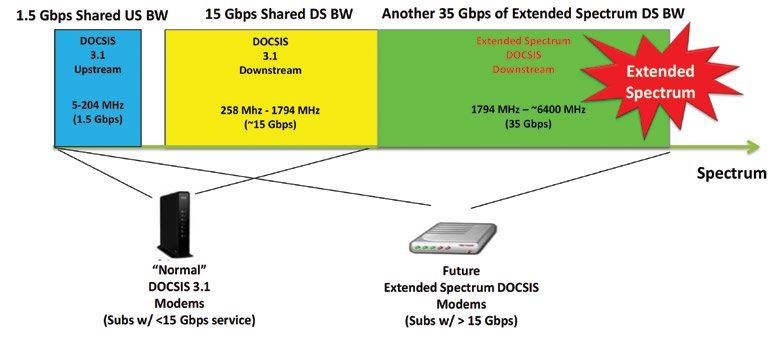
If we assume that we have a relatively large signal-to-noise ratio (with S/(N0*B) >> 1), then (1) can re-written as:

                    C = B*log22(S/(N0*B))

                    C = B*[log2(S/N0) – log2(B)]

                    C = B*[K – log2(B)]        (3)

          Where K=log2(S/N0).

          A typical doubling of the channel bandwidth from B to 2B will therefore result in a New C value (C2) given by:

                    C2 = 2B*[K - log2(2B)]

                    C2 = 2B*[K – log2(B) – log2(2)]

                    C2 = 2B*[K – log2(B) – 1]

                    C2 = 2B*[log2(S/N0) – log2(B) – 1]

                    C2 = 2B*[log2(S/(N0*B)) – 1]

                    C2 = 2B*[log2(S/N) – 1]           (4)

          In most real-world systems, the initial value of S/N is quite large (ex: SNRdB = 40 dB implies S/N = 10,000), so
          log2(S/N) = log2(10,000) = ~13.3 is relatively large (compared to 1). As a result, even though the SNR drops by 3 dB,
          it is still high (i.e. log2(S/N) >> 1), and therefore the new channel capacity value (C2) is close to double the channel
          capacity that existed before the channel bandwidth B was doubled. Thus, repeating this B-doubling process over
          and over can lead to great increases in the overall channel capacity (given by successive calculations of the C2 value).
          In most cases, the doubling yields beneficial results until the resulting modulation profiles begin to approach BPSK
          levels. This is clearly illustrated in Figure 3.

                          B (GHz)                 S/N         SNR (dB)             C =*log2(1+S/N) (Gbps)
                            0.75                10,000          40.00                        9.97
                             1.5                 5,000          36.99                       18.43
                              3                  2,500          33.98                       33.86
                              6                  1,250          30.97                       61.73
                             12                   625           27.96                       111.48
                             24                  312.5          24.95                       199.02

                                                               Figure 3: C vs. B

          HFC Plant Topics for Extended Spectrum DOCSIS Systems

          Extended Spectrum DOCSIS would require that several changes be made within the typical HFC network. Obviously,
          the HFC plant must have the ability to transmit and pass the higher-frequency signals from the head-end and across
          the fiber portion of the plant, through the fiber node, across the coaxial distribution leg of the plant, through
          amplifiers and taps, across the coaxial drop portion of the plant, through the coaxial in-home network, and to the
          modem in the home.

7 Using DOCSIS to Meet the Larger BW Demand of the 2020 Decade and Beyond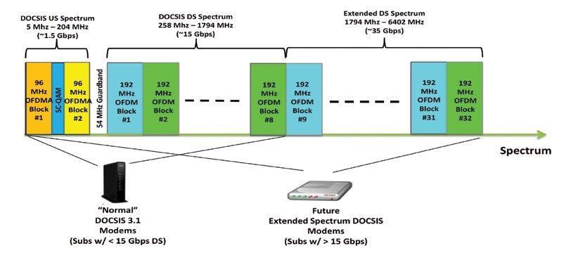
There are many ways to pass these Extended Spectrum DOCSIS signals through these elements. While it is
theoretically possible for high-frequency amplifiers to be designed for passing these signals, the authors believe that
most MSOs will likely prefer to wait until their HFC plants have been converted to Node+0 Fiber Deep architectures
before Extended Spectrum DOCSIS will be considered as a desirable and feasible technology. (Note: This eliminates
the cost of upgrading many amplifiers to the higher frequencies required for the Extended Spectrum network).
It seems fortuitous that many MSOs predict that they may be performing node splits down to Node+0 architectures
before or around the same time that the 10-15 Gbps DOCSIS 3.1 systems will be “running out of gas.” (Note: It is
also possible for MSOs to get to Node+0 architectures even if they keep their service groups large). As seen in
Figure 1, it is expected that the required bandwidth capacity of a typical Service Group will exceed the available
DOCSIS 3.1 bandwidth capacity in the early-to mid-2020’s. That is likely to be the time-frame when Extended
Spectrum DOCSIS may prove to be valuable. It is also the time-frame when Moore’s Law silicon improvements will
likely permit Extended Spectrum DOCSIS systems to be deployed (assuming designs begin in the latter portion of
the 2010 decade). This “perfect storm” of events implies that the early 2020’s may be a perfect time to consider for
initial deployments of Extended Spectrum DOCSIS systems.
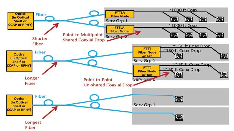
Once an MSO begins to deploy Node+0 Fiber Deep architecture designs, many variants of Extended Spectrum
DOCSIS systems can be envisioned.
Figure 4: Variants of HFC Plant Configurations for Extended Spectrum DOCSIS Delivery
Some MSOs may choose to have shorter fiber runs and longer coaxial runs, keeping their coaxial run lengths the
same distances with Node+0 network architecture. This would result in 600’ to 1250’ coaxial runs (and the lowest
bandwidth capacities), and we will designate these types of systems as Fiber-To-The-Last-Active (FTTLA) systems
(since the fiber is essentially run to the same location where the last amplifiers used to be). These FTTLA systems
would have hard-line coax carrying the Extended Spectrum DOCSIS signal across up to six taps, with each tap
having up to four subscribers connected to it.
Other MSOs may choose to have longer fiber runs and shorter coaxial runs, permitting their fiber to run all the way
to the tap and requiring the coaxial run to only hop across the drop cable. This would result in 100’ to 250’ coaxial
8 Using DOCSIS to Meet the Larger BW Demand of the 2020 Decade and Beyond
runs (and higher bandwidth capacities), and we will designate these types of systems as Fiber-To-The-Tap (FTTT)
          systems (since the fiber is essentially run to the tap). It is possible to design the Fiber Node within the FTTT system
          to have a single point-to-point coaxial connection from the Fiber Node’s Extended Spectrum DOCSIS transceiver
          directly to the tap, and that design approach may greatly reduce signal attenuation and noise funneling effects.
          Alternatively, the Fiber Node can be at the tap location, which reduces the coaxial attenuation even more.

          Still other MSOs may choose to have even longer fiber runs that go all the way to the home. This would result
          in zero-length coaxial runs (and the highest bandwidth capacities), and we will designate these types of systems
          as Fiber-To-The-Home (FTTH) or Fiber-To-The-Premise (FTTP) systems (since the fiber is run directly to the home).
          In essence, these types of systems are actually RF over Glass (RFoG) solutions. (Note: All of these variants are
          illustrated in Figure 4). A key potential benefit of these FTTH/FTTP systems is that they can use different lambdas
          for the Downstream path and the Upstream path, permitting much higher bandwidth capacities to be offered in
          both directions.

          MSOs could even choose to have fiber lengths inbetween those lengths described in the previous three paragraphs,
          so it should be apparent that many different design approaches to Extended Spectrum DOCSIS are permissible.

          In general, longer coaxial runs tend to lead to lower bandwidth capacities due to the higher attenuations (which
          increase as a function of both distance and frequency). However, longer fiber runs can also reduce bandwidth
          capacity due to dispersive and nonlinear noise effects (coupling energy between lambdas). A compromise will need
          to be found to maximize overall throughput.

          Tap Topics for Extended Spectrum DOCSIS Systems

          Some of the architectures defined in the previous section require that the Extended Spectrum DOCSIS signals pass
          through taps. For example, the top-most architecture in Figure 4 would require the taps to be updated.

          As a result, it is a given that new taps will need to be designed and deployed to carry the higher-bandwidth signals.
          This is still an area of research that needs to be performed before Extended Spectrum DOCSIS systems of that
          nature become practical.

          Optical Beat Interference Topics for Extended Spectrum DOCSIS Systems

          One of the obvious side-effects of Fiber Deep systems (which are pre-requisites to Extended Spectrum DOCSIS
          deployments) is the fact that there will be many Fiber Nodes to manage and feed.

          For MSOs, the delivery of signals to and from these many Fiber Nodes may require the use of wavelength-division
          multiplexing on the fiber or other fiber sharing techniques to minimize the number of unique physical fibers that
          must be pulled out to the Fiber Nodes. RF over Glass is one of the other popular fiber sharing techniques that
          permits multiple Fiber Nodes to share a lambda on the fiber. It is therefore quite possible that MSOs may choose to
          use RF over Glass (RFoG) techniques to deliver the signals from multiple Fiber Nodes up to the head-end. [MUTA]

          One of the obstacles to any Upstream Multi-point-to-point optical system (including Upstream RFoG) has been the
          existence of Optical Beat Interference (OBI). OBI is a dramatic form of signal degradation that occurs whenever two
          or more optical transmitters simultaneously transmit with closely-spaced optical wavelengths.

          OBI problems are exacerbated whenever the number of simultaneous upstream transmitters is increased. This
          can occur with increases in the number of channels (as with DOCSIS 3.0) or simultaneous transmitted codewords
          (as with DOCSIS 3.1). Thus, Extended Spectrum DOCSIS will only serve to exacerbate this problem by creating
          more bandwidth that is shared by the modems. As a result, good solutions to the OBI problem will be required if
          MSOs attempt to utilize RFoG techniques to combine signals from multiple Fiber Nodes in an Extended Spectrum
          DOCSIS system.

9 Using DOCSIS to Meet the Larger BW Demand of the 2020 Decade and Beyond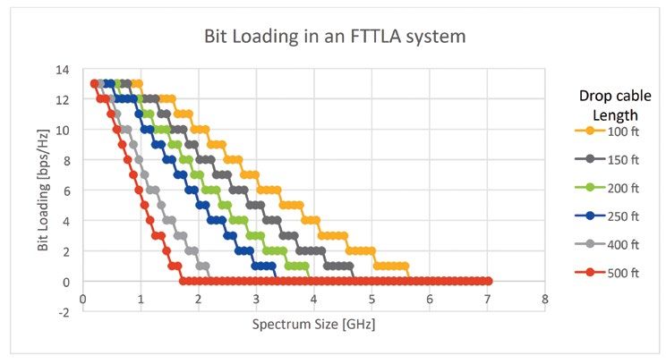
Two powerful approaches to OBI mitigation already exist. These include planned wavelength separation techniques
         and Hybrid PON techniques [MUTA]. With solutions like these in hand, MSOs should be able to roll out their
         Extended Spectrum DOCSIS systems and utilize RFoG techniques to connect to the many Fiber Nodes.

         Distributed Access Architecture Topics for Extended Spectrum DOCSIS Systems

         Extended Spectrum DOCSIS offers a very flexible design. Due to this flexibility, it should be able to work very well
         with traditional Amplitude Modulated Optical signals being carried over the fiber portion of the HFC network. (Note:
         This is the type of solution that would be used within the RFoG solutions described in the previous section).

         However, nonlinear optical effects resulting from interactions between lambdas on any lengthy wavelength-division
         multiplexed fiber may reduce the SNR values and reduce the throughput of the Extended Spectrum DOCSIS system.

         As a result, MSOs may alternatively choose to use Distributed Access Architectures (DAAs) to deliver the signals over
         the fiber portion of the HFC network. With DAAs, the fiber carries digital optics (Ethernet or xPON signals) from
         the head-end to the Fiber Node, and the Fiber Node produces the Amplitude Modulated signal that is ultimately
         transmitted over the coaxial portion of the HFC network. [CLO2]

         Two different variants of DAA architectures are being considered by MSOs—Remote PHY architectures and Remote
         MACPHY architectures.

         Extended Spectrum DOCSIS systems could be built using either of these DAA variants. In both cases, there are
         several benefits that would result. First, the use of a DAA approach would ensure that the SNR of the signals would
         not be significantly reduced by the nonlinearities within the fiber portion of the HFC network. Second, the use of
         DAA systems would help to reduce the power and space requirements in MSO head-ends when fiber deep solutions
         have created the need to support many small Service Groups. Third, the use of DAA systems (and digital optics)
         would also permit MSOs to place more lambdas on their wavelength-division multiplexed fibers. Fourth, the use
         of DAA systems (and digital optics) eliminates the presence of OBI within the digital fiber (since OBI only occurs in
         Amplitude Modulated optical systems).

         Because of all of these reasons, MSOs who move to Extended Spectrum DOCSIS will have the option to use either
         centralized or distributed access architectures.

         Spectrum Topics for Extended Spectrum DOCSIS Systems

         With Node+0 systems in place, MSO networks will be ready to carry Extended Spectrum DOCSIS signals. The signals
         themselves may take the form of a stack of 192 MHz OFDM Downstream blocks (or a stack of 96 MHz OFDMA
         Upstream blocks) that inhabit regions of the spectrum beyond 1794 MHz.

         The actual amount of spectrum that might be useable for this stack of OFDM/OFDMA blocks is a function of many
         parameters, including the signal launch power, the noise power injected on the fiber, the length of the fiber, the
         number of lambdas on the fiber, the wavelengths of the multiplexed lambdas, the noise power injected on the
         coax, the length of the coax, the attenuation of the coax, the amount of loss in taps, the amount of loss in splitters,
         modem receiver noise figure, etc.

         Thus, depending on the design of the Node+0 system, different spectral widths will be allowed to carry Extended
         Spectrum DOCSIS signals. Thus, it is possible that Extended Spectrum DOCSIS systems of various flavors could
         be deployed differently by different MSOs. Some may choose to limit Extended Spectrum DOCSIS operation to
         ~2.5 GHz. Others may choose to limit Extended Spectrum DOCSIS operation to ~7 GHz. Still others may choose
         to push Extended Spectrum DOCSIS operation all the way to ~10-25 GHz. In each case, the HFC plant must be
         appropriately conditioned (creating deeper fiber runs and shorter coaxial runs) to guarantee successful OFDM and
         OFDMA operation.

10 Using DOCSIS to Meet the Larger BW Demand of the 2020 Decade and Beyond
As an example, consider a system with coaxial lengths that are short enough to permit ~6.4 GHz of spectrum to be
passed. If an Extended Spectrum DOCSIS system using ~6.4 GHz of spectrum were deployed, then it is possible that
the system might place DOCSIS Downstream spectrum from 258 MHz to 6402 MHz. This spectrum is large enough
to hold thirty-two 192 MHz OFDM blocks. It is expected that channel bonding can be used across all of the 32
OFDM blocks. This is illustrated in Figure 5. (Note: It is also possible that larger OFDM blocks could be defined in a
future Extended Spectrum DOCSIS specification. This would lead to the need for less OFDM blocks in the spectrum
and less use of DOCSIS channel bonding).
The spectrum in Figure 5 is quite asymmetrical, with much more Downstream bandwidth capacity than Upstream
bandwidth capacity. The spectrum could also be divided in a different way.
Figure 5: Asymmetrical Extended Spectrum DOCSIS in 2-band FDD Spectrum Offering
Figure 6: Symmetrical Extended Spectrum DOCSIS in 2-band FDD Spectrum
Offering ~20 Gbps x ~ 20 Gbps US in ~6.4 GHz
11 Using DOCSIS to Meet the Larger BW Demand of the 2020 Decade and BeyondFigure 7: Symmetrical Extended Spectrum DOCSIS in 3-band FDD Spectrum
Offering ~22Gbps DS x ~16.5 Gbps US in 6.4 GHz
For example, a more symmetrical version of Extended Spectrum DOCSIS could also be configured as shown in
Figure 6, where the Upstream spectrum ranges from 5 to 2597 MHz and the Downstream spectrum ranges from
3330 to 6402 MHz. This requires a larger 733 MHz guard band between the two directional spectra, and that
leads to slightly lower overall bandwidth capacities. (Note: It may be possible to eliminate the guard bands in these
designs, which is a topic that is still under study within the Full-Duplex DOCSIS effort [FDX] among MSOs, vendors
and CableLabs). Note that this particular configuration, shown in Figure 6, will not permit DOCSIS 3.1 modems to
operate, because there is no Downstream spectrum in the “normal” Downstream portion of the spectrum where
DOCSIS 3.1 operates.
Another symmetrical version of Extended Spectrum DOCSIS is shown in Figure 7. This particular solution has the
benefit of supporting symmetrical bandwidth capacities (with similar bandwidth capacities in the Upstream and
Downstream directions) while also permitting DOCSIS 3.1 modems to operate in the system. The disadvantage is
that three bands (two Upstream bands and one Downstream band) must be utilized, and this leads to even more
guard band being added to the system. Furthermore, the limited upstream transmit power along with the high
attenuation at the upper frequencies will cause the overall bandwidth capacity to be further reduced.
Full Duplex and Half Duplex Topics for Extended Spectrum DOCSIS Systems
MSOs are continually being pushed by subscribers and competitors to increase their bandwidth capacities. In
recent years, xPON service providers have begun challenging MSOs and are beginning to push MSOs to increase
their DOCSIS 3.1 Upstream bandwidth capacities. In response to these challenges, MSOs and their vendors are
exploring many ways to provide more bandwidth capacity. As an example, there are currently very active studies
under way to identify powerful, new techniques for operating the DOCSIS 3.1 Upstream channels on the same
frequencies as the DOCSIS 3.1 Downstream channels. At least two different approaches for frequency spectrum
sharing are being considered.
One of the frequency spectrum sharing approaches is based on Full Duplex operation, whereby the Upstream and
Downstream signals occupy the same coax and the same portion of the spectrum at the same time. The signals
essentially pass right through one another, and the receivers must detect and demodulate the arriving signal in the
presence of the interference or “noise” from the signal propagating in the opposite direction. This requires the use
of noise cancellation techniques in the CCAP Upstream Receiver. There must also be ways to circumvent noise at the
12 Using DOCSIS to Meet the Larger BW Demand of the 2020 Decade and Beyondmodem Downstream Receiver, because non-ideal isolation in taps can permit energy from Upstream transmissions
from a modem to couple into the Downstream spectrum on nearby, neighbor modems (see Figure 8). While solutions
to these problems have some challenges and are still being studied, it is quite possible that some form of Full Duplex
DOCSIS [FDX] may be operating on DOCSIS 3.1 systems in the next few years.
It should be noted that an extended spectrum DOCSIS system based on FTTT will likely result in a point-to-point
coaxial connection between the fiber node, which could be at the tap location, and the modem. Therefore,
interference between neighboring modems in a Full Duplex DOCSIS system is essentially eliminated. This may lead
to many simplifications as well as performance enhancements within Full Duplex DOCSIS systems because echo
cancellation can be added at both ends.
Figure 8: SNRs in Modems due to Upstream Transmission from Neighbor (Modem #5)
The second frequency spectrum sharing approach is based on Half Duplex TDD operation, whereby the
Upstream and Downstream signals occupy the same coax and the same portion of the spectrum, but they share
the resources in time by allowing only Upstream transmissions at one moment in time and by allowing only
Downstream transmissions at a different moment in time. This requires well-synchronized MAP generation for
Upstream transmissions and scheduling for Downstream transmissions. Solutions to these scheduling problems
have some challenges and are still being studied, but it is also quite possible that some form of Half Duplex
DOCSIS may be operating on DOCSIS 3.1 systems in the next few years.
If either Full Duplex or Half Duplex DOCSIS operation becomes a reality for DOCSIS 3.1, it is likely that it would
also be used in an Extended Spectrum DOCSIS environment as well. Fortunately, the similarities between DOCSIS
3.1 and Extended Spectrum DOCSIS should permit any successful Full Duplex or Half Duplex approach to be easily
applied to Extended Spectrum DOCSIS systems.
13 Using DOCSIS to Meet the Larger BW Demand of the 2020 Decade and BeyondFigure 9: Asymmetrical Extended Spectrum DOCSIS w/ Shared Spectrum in ~6.4 GHz
Figure 10: Symmetrical Extended Spectrum DOCSIS w/ Shared Spectrum in ~6.4 GHz
As an example, Figure 9 and Figure 10 show examples of spectral maps with overlapping Upstream OFDMA blocks
and Downstream OFDM blocks. Figure 9 shows a map that may permit DOCSIS 3.1 modems to interoperate on the
spectrum with Extended Spectrum DOCSIS modems, whereas Figure 10 shows a map that attempts to maximally fill
the spectrum with Extended Spectrum DOCSIS operation (which likely precludes the use of DOCSIS 3.1 modems on
the spectrum). These spectral maps can be used for either Full Duplex or Half Duplex operation.
14 Using DOCSIS to Meet the Larger BW Demand of the 2020 Decade and BeyondOFDM/OFDMA Topics for Extended Spectrum DOCSIS Systems
It should be clear that Extended Spectrum DOCSIS is leaning heavily on the good work already done within the
DOCSIS 3.1 specification committee. At a fundamental level, Extended Spectrum DOCSIS basically proposes to
extend the use of Downstream OFDM and Upstream OFDMA techniques to other portions of the RF spectrum.
There are several reasons why the authors believe that this is a good idea. First, it permits Extended Spectrum
DOCSIS to be created without a lot of new specification work. But more importantly, the authors believe that there
may be important benefits that result from the use of DOCSIS 3.1’s OFDM and OFDMA techniques. In particular, it
may greatly aid in the passing of the high-frequency signals across both the fiber portion of the HFC network and
the coaxial portion of the HFC network.
For transmissions across the fiber portion of the HFC network, one of the biggest challenges for Extended Spectrum
DOCSIS will be to find ways to overcome the signal-distorting dispersion effects (resulting from varying propagation
speeds for signals with different frequencies on the fiber). The impact of this dispersion on the OFDM signals is still
being studied, but there may be some interesting results that may be found.
For transmissions across the coaxial portion of the HFC network, one of the biggest challenges for Extended
Spectrum DOCSIS will be to find ways to overcome the large attenuation that will occur at the high frequencies
(due to skin effect issues within the coax). Fortunately, OFDM can again be used to help circumvent this problem,
because it permits the use of the variable bit loading feature. This feature permits the system to use lower
modulation orders for high-frequency regions of the RF spectrum where attenuation leads to reduced signal powers
and therefore reduced SNRs.
As a result, it is quite possible that the use of OFDM for Extended Spectrum DOCISS may greatly help with the
transmission of the high-frequency signals in the resulting systems.
Extended Spectrum DOCSIS Coaxial Simulation Results
As mentioned in the previous section, carefully-optimized variable bit loaded profiles for the OFDM signals will
undoubtedly help with the transmission of the high-frequency Extended Spectrum DOCSIS signals across the coax.
The authors have begun exploring the performance levels of bit loading the Extended Spectrum DOCSIS signals. In
particular, simulations of two possible configurations of the future were created: an FTTLA (Fiber to the Last Active)
system and an FTTT (Fiber to the Tap) system. In each case, an attempt was made to identify the performance limits
that impact the optical link SNR. Several simplifying assumptions were made. These include:
1. The only sources of noise are the noise at the output of the last amplifier (expressed through the source SNR), the
Johnson-Nyquist thermal noise floor at the CPE and the CPE input circuitry’s own noise contribution (expressed as
the CPE noise figure). We explicitly excluded external noise components due to damaged cables or poor in-home
wiring because the task at hand is to explore the limiting factors in the capacity of the HFC plant itself.
2. The total RF power at the output of the Fiber Node is maintained at a fairly reasonable level of (say) 68 dBmV,
although a range of values are examined.
3. The distribution cable between the last active component and the taps is 0.625” hard line. Its attenuation is
calculated over an extended frequency range (beyond the normal recommended frequency range of 0-3 GHz)
using standard formula for resistive loss in the conductors and tan-δ loss in the dielectric.
15 Using DOCSIS to Meet the Larger BW Demand of the 2020 Decade and Beyond4. The coaxial drop cable is assumed to be RG-6. Its attenuation is similarly calculated over an extended frequency
range using the same approach as was used for the distribution cable.
5. The CPE’s demodulator has an implementation margin of 3 dB at high SNR values. Practical demodulators will
generally not achieve theoretical performance for a variety of reasons (e.g. quantization noise, limited number
of iterations in LDPC decoders, etc.); this margin ensures that the demodulator’s MER exceeds the theoretical
minimum MER required to decode a signal with particular modulation depth.
6. The total amount of PHY and MAC overhead is assumed to be 20%. PHY overhead includes the loss of capacity
associated with guard bands, pilots, signaling channels, LDPC FEC, and cyclic prefixes. The MAC overhead is
associated with framing overheads and MAC messaging.
7. For half-duplex systems, the calculated capacity is the total bitrate in either direction; it may be split in any ratio
between upstream and downstream traffic.
8. For full-duplex systems, the calculated capacity is the bitrate in one direction; the total capacity may be double
this value for true full-duplex operation.
9. All possible QAM modulation orders (and associated bit-loading values) are used, down to BPSK; this differs
from the current DOCSIS 3.1 standard, which uses a minimum of 16-QAM modulation for data. However, the
specifications can be augmented with lower QAM orders to support the extended spectrum feature.
Given the above assumptions, the simulation explored the impact of various system parameters:
1. The effect of total transmitted RF power on the system capacity is examined.
2. The transmitted RF power may be distributed over the occupied spectrum either in a uniform manner (i.e. a flat
Power Spectral Density) or with a tilt being applied. Both of these cases are examined, and the optimum PSD that
maximizes the capacity is determined.
3. The effect of CPE input stage quality, i.e. the Noise Figure (NF) of the CPE’s input circuitry in front of the
demodulator, is explored.
4. The effect of source quality, i.e. the available SNR at the output of the last amplifier as signals transit over the
optical link and previous amplifiers, is explored. In the remainder of this article, we use the term “source SNR” or
“amplifier SNR” to refer to this parameter.
5. Different coax drop lengths are used in the simulation to examine the impact of this parameter on throughput.
The available RF bandwidth is assumed to be a little less than the cutoff frequency of the hard-line coax (for FTTLA)
or RG-6 cable (for FTTT), with a somewhat arbitrary absolute maximum of 25 GHz. The relevant cutoff frequencies
are 8.05 GHz for 0.625” hardline and 28 GHz for RG-6. For FTTLA, we consider signals up to 7 GHz; for FTTT, we
consider signals up to 25 GHz. Multiple simulation runs, corresponding to different spectrum sizes, were performed
to determine the optimal spectrum size that maximizes the throughput. For each of these runs, the total power was
divided across the spectrum supported in that case.
Note that, while we use the downstream terminology in the remainder of this paper (i.e., the “source” is the last
amplifier, the demodulator is at the CPE) the analysis applies equally to the upstream direction, where the source
would be the CPE and the demodulator would be either at the node (DAA) or the headend (CAA).
16 Using DOCSIS to Meet the Larger BW Demand of the 2020 Decade and BeyondExtended-Spectrum System Capacity for FTTLA Systems
Using the assumptions listed above and the architecture shown in Figure 8, the resulting received signal SNRs,
supported modulation levels, and bandwidth capacities can all be calculated for different spectrum sizes and
different distances of typical RG-6 drop cables. The resulting bandwidth capacity is shown in Figure 11 and the
corresponding bit loading values (in bits per symbol) are also shown in Figure 12, where the QAM order can be
calculated from the bit loading values using the following formula:
QAM Order = 2(bit loading). (5)
For this first-stage analysis, the following parameters have been used:
1. Total transmitted power of 68 dBmV (equivalent to 100 mW).
2. Amplifier SNR of 40 dB.
3. CPE NF of 10 dB.
4. No tilt is applied.
Variations in these parameters will be explored later in this paper.
From these figures, it can be seen that there is a definite bandwidth capacity benefit associated with the
extension of the spectrum. This benefit is realized until the bit loading drops to a value of 1 (which corresponds
to BPSK modulation).
It is also evident that the peak capacity is achieved at a particular spectrum size which is less than the maximum
spectrum supported by the cable, but more than the current DOCSIS 3.1 limit of 1.794 GHz. This seems to
contradict the capacity trend that was described in Figure 3, where increasing the spectrum always leads to an
increase in capacity. However, this is only true if the SNR is high. For example, at the typical drop length of 150
ft, the peak capacity of ~27 Gbps is seen with a spectrum size of ~4.5 GHz. This behavior can be explained as
follows: as the spectrum increases, more transmitted power is diverted to higher frequencies. Initially, as the
spectrum size is small, the SNR stays high as we increase the spectrum, leading to increased overall capacity.
However, if the spectrum increases further beyond a certain point, power is distributed to frequencies where the
attenuation is so great that no modulation can be supported. This lost power detracts from the throughput at
lower frequencies, reducing the overall capacity.
As one would expect, the capacity decreases with increasing drop length. Ironically, the optimal spectrum size
for the longest drop lengths of 400 ft and 500 ft, is equal to, or slightly higher than, the maximum supported DS
frequency in the DOCSIS 3.1 specifications (i.e. 1.794 GHz).
17 Using DOCSIS to Meet the Larger BW Demand of the 2020 Decade and BeyondFigure 11: Capacity vs. Spectrum Size in an FTTLA system
Figure 12: Bit Loading vs. Spectrum Size in an FTTLA system
Extended-Spectrum System Capacity for FTTT Systems
The simulations of the FTTLA system above indicated a potential capacity increase of 2x to 3x relative to the capacities
promised by the current DOCSIS specifications. As MSOs go deeper in fiber, more capacity can be offered. For example,
in an FTTT system, hardline and tap losses are eliminated; only the RG-6 drop line attenuation remains.
Additionally, the drop cable, due to its smaller geometry, has much higher cutoff frequency. Admittedly, its attenuation
per unit length is higher than that of the hardline, but this is compensated by the shorter run lengths.
Figure 13 below shows the throughput vs. spectrum width for FTTT systems with various drop lengths. Moreover, Figure
14 shows the corresponding bit loading levels. It is compelling to note the potential high throughputs that are achievable
across a point-to-point RG-6 coax carrying DOCSIS 3.1 OFDM signals. As an example, a 500 ft. length of RG-6 carrying a
5 GHz-wide OFDM spectrum would be capable of transmitting ~30 Gbps of throughput from the Fiber Node at the tap
18 Using DOCSIS to Meet the Larger BW Demand of the 2020 Decade and Beyondlocation to the home. On the other hand, a 150 ft drop cable can offer about 200 Gbps with 25 GHz spectrum.
While second-order effects would likely reduce these bandwidth capacities to some extent, the message is clear;
support for relatively large throughputs is likely to be possible on reasonable lengths of drop cables into the homes.
Figure 13: Capacity vs. Spectrum Size in an FTTT system
Figure 14: Bit Loading vs. Spectrum Size in an FTTT system
The Effect of Total Transmitted Power on Extended Spectrum Capacity
The simulations above were performed with a total power setting of 68 dBmV (100 mW), which is a typical value
for existing nodes. However, higher power levels (e.g. 74 dBmV or 400 mW) have been used in some circumstances,
at the cost of higher power consumption in the RF amplifier. On the other hand, lower power amplifiers might
well be useful in order to facilitate a low-cost, low power design; this is particularly true of the upstream, where
CPE power consumption is likely to be constrained for environmental reasons. Therefore it is useful to examine the
effects of different RF power levels on system capacity.
19 Using DOCSIS to Meet the Larger BW Demand of the 2020 Decade and BeyondFigure 15 shows the effect of changing the total RF power in an FTTLA system. Three scenarios are studied: one
for a “high fidelity” scenario, with an amplifier SNR of 45 dB and a CPE NF of 5 dB; the second is a “mid-fidelity”
scenario, with an amplifier SNR of 40 dB and a CPE NF of 10 dB; the third is a “low-fidelity” scenario, with an
amplifier SNR of 35 dB and a CPE NF of 15 dB. All other parameters were maintained the same as in the previous
simulations. In each case, the peak capacity of the system was calculated at a particular transmitted RF power. Figure
16 shows the equivalent result in an FTTT system.
It can be observed from these plots that the effect of transmitted RF power (which is broadly proportional to
amplifier power consumption) on capacity is relatively small. A 3 dB reduction in RF power only produces ~10%
reduction in capacity. This is one of the tradeoffs that would need to be considered in designing extended-
spectrum equipment.
Figure 15: Capacity vs. Amplifier Output Power in an FTTLA system
Figure 16: Capacity vs. Amplifier Output Power in an FTTT system
The Effect of Source SNR and CPE Noise Figure on Extended Spectrum Capacity
Regarding source SNR, it is clear that the current generation of CMTS and CCAP downstream modulators can
comfortably generate full-spectrum (1.0 or 1.2 GHz) downstream signals with SNR and MER values exceeding 50
dB; DAA devices (Remote PHY, Remote MAC-PHY) are likely to have similar signal quality. The question is whether
extended-spectrum DOCSIS equipment could be expected to have similar performance over the full frequency range.
20 Using DOCSIS to Meet the Larger BW Demand of the 2020 Decade and BeyondWhile DAC speeds have increased dramatically over the last decade, and will probably continue to increase, it
may be too optimistic to assume that direct-RF DACs generating signals at these high frequencies (i.e. > 20 GHz)
with DRFI-type fidelity and reasonably low cost and power consumption to be available in the 2020-2030 decade.
While such devices may become available if the recent trends continue, our analysis will not make this assumption.
If such equipment is not available in the time frame when extended spectrum devices are needed, then various
techniques can be utilized to achieve the required performance over a full-spectrum of 7 GHz or 25 GHz, needed
for FTTLA or FTTT, respectively. For example, multiple DACs in a single package could feed overlapping upconverters
with portions of the required full-bandwidth signal; the DOCSIS 3.1 standard lends itself very well to this kind of
technique, where multiple synchronous OFDM signals can be supported without guard bands between them.
However, one would expect some reduction in signal quality in these conversion stages. Other techniques can be
used but they would presumably carry similar penalties. Therefore, the effect of lower SNR values was included in
our analysis, where the range of 35 dB to 45 dB is considered.
In Fig. 17, the CPE noise figure, which is largely determined by cost considerations, is investigated because it is
difficult to predict the scale of improvements in the performance of electronic devices over the next 10-15 years.
In particular, a NF of 5 dB might be expensive to achieve in a CPE, whereas a NF of 15 dB should be achievable
relatively cheaply. The analysis here was conducted with NF values that range from 5-15 dB.
Figure 17 shows the effect of varying source SNR on system capacity in a FTTLA system for several values of CPE NF.
Figure 18 shows equivalent plots for an FTTT system. It can be seen that a 3 dB change in NF changes capacity be
10-15%, but this is modest compared to the effects of the other parameters (especially spectrum size and coax drop
length). Similarly, a change in transmit SNR of 3 dB changes the capacity by ~2%, which is relatively insignificant.
In order to simplify the analysis, we will assume a source SNR of 40 dB and CPE NF of 10 dB. These values are both
in the middle of the somewhat conservative ranges. Moreover, the effect of changing these values is relatively
modest, as explained earlier.
Figure 17: Capacity vs. Source SNR in an FTTLA system
21 Using DOCSIS to Meet the Larger BW Demand of the 2020 Decade and BeyondFigure 18: Capacity vs. Source SNR in an FTTT system
The Effect of RF Tilt on Extended Spectrum Capacity
In HFC systems, it is common practice to apply an RF “up-tilt” to the transmitted RF signal at the amplifier. The goal is
to compensate for the attenuation of the coax cables (hard-line distribution cables and RG-6 drop lines) which causes a
downward tilt across the spectrum. If it were possible to do this perfectly (which it isn’t, as different modems will suffer
from different tilts due to differing lengths of coax run), the result would be that every 6 MHz channel would be received
at the same RF power. This has obvious advantages in a traditional digital (or mixed analog/digital) TV system, where a
receiver would demodulate a single channel, and would only accept a relatively limited range of channel powers (typically
+ 15 dB) in order to successfully demodulate a QAM signal (usually 256-QAM) with an SNR target of ~35 dB.
While this target of flat received power simplifies the design of single channel demodulators, it is not clear that it
optimizes the capacity of a multichannel system, in terms of total throughput per unit transmitted power, especially
when multiple QAM orders are available. In this section, we look at the effect of applying tilt to the extended-spectrum
DOCSIS signal.
The previous capacity curve in Figures 11-18 were all calculated with no tilt; the RF power was evenly distributed across
the spectrum, giving a constant PSD at the RF amplifier output. By way of comparison, one representative case (FTTLA
with a 150-ft drop cable and 68 dBmV Tx power) was re-simulated with a tilt applied. The tilt was calculated to exactly
cancel the attenuation of the 2 types of coax, while maintaining the same total amplifier output power. The result was a
signal with a flat PSD at the receiver. The results are shown in Figure 19.
Figure 19: Effect of tilt on capacity at different spectrum widths in an FTTLA system
22 Using DOCSIS to Meet the Larger BW Demand of the 2020 Decade and BeyondIt is clear that the tilted transmission produces a lower capacity than the flat transmission. This can be explained by the
fact that the tilt process, by its very nature, pumps more power into the highly attenuated upper frequencies than it does
into the lower frequencies; much of this power is ultimately lost in the noise.
While it is clear from Figure 19 that a no-tilt system has a higher capacity than a fully tilted one, it is not obvious that this
is the optimum setting. To explore this possibility, simulations were run with different degrees of tilt. Herein we introduce
a parameter, the “tilt factor”, to indicate the amount of applied tilt. Full tilt (a tilt factor of 1) is the case where the
applied tilt completely cancels the coax tilt; any other tilt (a tilt factor of f) is where the applied tilt (in the dB scale) is
f times the coax tilt (but in the opposite direction). In this way, even negative tilts (which reinforce the coax tilt instead of
canceling it) may be considered. The results of these simulations are plotted in Figure 20. It is clear from this figure that
the optimum tilt is zero (or very close to it).
Figure 20: Capacity vs. Tilt Factor
Extended Spectrum DOCSIS Experimental Results
To begin showing that Extended Spectrum DOCSIS operation is a feasible solution for the future, an experiment was
conducted to transmit a single 96 MHz OFDM block across a typical 150’ coaxial drop cable.
In this experiment, a 96 MHz 4K QAM DOCSIS 3.1 OFDM signal was generated using the E6000 CER at 600 MHz center
frequency. The samples of this signal were recorded using Keysight vector signal analyzer (PXA N9030A). These samples
were then stored on a Keysight function generator (MXG N5182B) which was used to upconvert the OFDM signal to 6
GHz center frequency. The ~50 dBmV OFDM signal was then transmitted over the 150’ RG-6 coaxial drop cable and was
received and demodulated by a Keysight vector signal analyzer (N9030A). The results of the experiment are shown in
Figure 21, where the 4K QAM signal was successfully received with no codeword errors be the vector signal analyzer. A
live 8-minute demonstration of the experiment described here can be seen via the video posted by CableLabs [Demo].
23 Using DOCSIS to Meet the Larger BW Demand of the 2020 Decade and BeyondFigure 21. Experimental Results
Conclusions
This paper proposed a new flavor of DOCSIS called Extended Spectrum DOCSIS, which is aimed at increasing the
overall bandwidth capacity that can be provided to subscribers within an HFC network or within a FTTH RFoG network.
The basic idea is to extend the use of OFDM Downstream blocks and OFDMA Upstream blocks into regions of the
spectrum that are not currently permitted by the DOCSIS 3.1 specification. Thus, OFDM Downstream blocks would
be placed above 1794 MHz, and OFDMA Upstream blocks would be placed above 204 MHz. The blocks could be
positioned in a way that yields FDD operation or could be positioned in a way that yields Full Duplex or Half Duplex
TDD operation.
Analyses within the paper show that it may be possible to get 50 Gbps or even 100-200 Gbps of bandwidth capacity
to be passed across an HFC network (if the plant is appropriately adjusted). Typically, higher bandwidth capacities
result from deeper fiber runs and shorter coaxial runs. However, more research is still required before the details of
Extended Spectrum DOCSIS system operation can be outlined.
Extended Spectrum DOCSIS has many potential benefits that can help MSOs satisfy the exponentially-increasing
bandwidth demands of the future.
First, it is a technology that is based on the existing DOCSIS 3.1 technology. As a result, complicated, time-
consuming specification work is likely not going to be required. It could be a relatively simple addendum to the
existing DOCSIS 3.1 specification.
As a result of its re-use of DOCSIS 3.1 modulation approaches, it should be clear that Extended Spectrum DOCSIS
will be backwards-compatible with existing DOCSIS equipment. It is likely that DOCSIS 3.1 equipment and pre-
DOCSIS 3.1 equipment will be able to coexist and operate in lower portions of the spectrum, and Extended
Spectrum DOCSIS modems will be able to operate in both the lower portions of the frequency spectrum (along with
earlier DOCSIS equipment) and in the higher portions of the frequency spectrum.
Since Extended Spectrum DOCSIS uses the same provisioning, configuration, and management systems as DOCSIS,
another key benefit is its ability to eliminate the unnecessary operational challenges that oftentimes accompany the
introduction of a new technology.
24 Using DOCSIS to Meet the Larger BW Demand of the 2020 Decade and BeyondYou can also read