Digital multi-programme TV/HDTV by satellite
←
→
Page content transcription
If your browser does not render page correctly, please read the page content below
Digital multi–programme TV/HDTV
by satellite
M. Cominetti (RAI)
A. Morello (RAI)
M. Visintin (RAI)

                                                                                          The progress of digital technology
                                        1.   Introduction                                 since the WARC’77 is considered
                                                                                          and the perspectives of future
                                The significant progress of digital techniques in         applications via satellite channels
                                production, transmission and emission of radio
                                                                                          are identified. Among these, digital
                                and television programmes is rapidly changing the
                                established concepts of broadcasting.
                                                                                          multi–programme television
                                                                                          systems, with different quality levels
                                                                                          (EDTV, SDTV) and possible
                                The latest developments in VLSI (very–large scale
                                                                                          evolution to HDTV, are evaluated in
                                integration) technology have significantly contrib-
                                uted to the rapid emergence of digital image/video        terms of picture quality and service
                                compression techniques in broadcast and informa-          availability on the satellite channels
                                tion–oriented applications; optical fibre technolo-       of the BSS bands (12 GHz and
                                gy allows broadband end–to–end connectivity at            22 GHz) and of the FSS band (11
                                very high bit–rates including digital video capabil-      GHz) in Europe. A usable channel
                                ities; even the narrow–band terrestrial broadcast         capacity of 45 Mbit/s is assumed, as
                                channels in the VHF/UHF bands (6–7 MHz and 8              well as the adoption of advanced
                                MHz) are under investigation, in the USA [1] and          channel coding techniques with
                                in Europe [2], for the future introduction of digital     QPSK and 8PSK modulations. For
                                television services.
                                                                                          high and medium–power satellites,
                                                                                          in operation or planned, the
                                The interest for digital television in broadcasting       receiving antenna diameters
                                and multimedia communications is a clear exam-
                                                                                          required for correct reception are
                                ple of the current evolution from the analogue to
                                the digital world.
                                                                                          reported. High–level modulations
                                                                                          (16QAM, 32QAM, 64QAM) are
                                                                                          considered for distribution of the
                                The satellite channels, either in the BSS bands
                                                                                          satellite signal in cable networks.
                                (broadcast satellite service) at 12 GHz or in the
                                FSS bands (fixed satellite service), offer an impor-
                                tant opportunity for a short time–scale introduc-
                                tion of digital multi–programme television ser-         In a longer term perspective, the new frequency
Original language: English.
                                vices, with possible evolution to high–definition       band (21.4 to 22 GHz) allocated by the WARC’92
Manuscript received 3/6/1993.   television (HDTV).                                      to wide RF–band HDTV (W–HDTV) services in

30                                                                                                   EBU Technical Review Summer 1993
                                                                                                                         Cominetti et al.
Regions 1 and 3 will also offer important opportu- C/N values of 19 dB and 16.9 dB are then achiev-
nities for new services. able in Italy (climatic zone K) for 99% and 99.7%
of the worst month, respectively. Further improve-
ments are expected with the next generation of re-
2. Technology trends and the ceivers (NF = 0.8 dB), soon to be available on the
evolution of satellite market.
television
Technology progress in receiving antennas is also
Satellite television is developing rapidly in Europe very promising. For example, modern 50–60 cm
in response to the emergence of new technologies receiving antennas show an improved radiation
and the creation of a favourable commercial envi- pattern, providing the same protection against in-
ronment through the deregulation of the commu- terference as was assumed by the WARC’77 Plan
nications sector. The success of satellite broadcast- for 90–cm dishes.
ing depends on the programmes provided and,
increasingly, on the way programme–providers Significant improvements have also been made in
can offer an attractive package for the various au- satellite technology. Today, improved power sup-
diences. The set of parameters characterising the ply performance permits continuous operation un-
satellite are then important strategic factors con- der eclipse conditions, allowing exploitation of a
tributing towards penetration of a dedicated mar- wider arc of orbital positions. Shaped–beam
ket. Parameters to be considered are: orbital posi- technology can be employed to cover the service
tion, type of polarization (circular or linear), area efficiently, with perhaps only 1 dB variation
frequency band, satellite power, coverage, avail- in eirp, and to provide a geographical isolation ca-
ability of backup capacity. Equally important are: pability not feasible with a simple beam.
technical quality and number of programmes de-
livered to the users, availability of reliable trans- Finally, the progress of receiving systems and sat-
mission systems and low–cost receivers. ellite technology allows a significant relaxation of
the satellite power with respect to the WARC’77
assumptions. This is the key of the success of DTH
2.1. The need for modernisation of (direct–to–home) television services via medium–
the WARC’77 Plan power pan–European telecommunications satel-
lites (e.g. Eutelsat II, Astra) in the FSS band, which
The WARC’77 Plan was established for the use of
are no longer penalised by their relatively low
BSS in the band 11.7–12.5 GHz, for Regions 1 and
eirps. A large number of television programmes
3. The Plan assigned five channels to each country,
are now available in Europe from these satellites,
with a channel spacing of 19.18 MHz. It was based
either directly or through cable distribution net-
on FM/TV systems (PAL, SECAM, NTSC) with
works.
13.5 MHz/V frequency deviation and 27 MHz re-
ceiver bandwidth. The protection ratios are 31 dB This new scenario has stimulated the need for a
(co–channel, CCI) and 15 dB (adjacent channel, modernisation of the WARC’77 Plan in order to
ACI). fulfil the increasing demand for new programmes
with supranational and pan–European coverages
For the case of Italy, a satellite eirp (effective iso- and offers the prospects of more efficient utilisa-
tropic radiated power) of about 64 dBW at the tion of the spectrum and orbit resources (Resolu-
beam centre was assigned in order to guarantee a tion 524 of WARC’92).
carrier–to–noise ratio (C/N) of 14 dB (in 27 MHz)
at the –3 dB area contour for 99% of the worst The adoption of digital techniques allows im-
month, assuming a receiving system with a 90–cm provements in the capacity without changing the
antenna and a figure–of–merit (G/T) of 6 dB/°K. Plan [3, 4], whilst complying with the required
This C/N value is necessary to achieve adequate protection ratios for analogue TV/FM systems and
service quality with analogue FM/TV systems. allowing a significant eirp reduction. In fact (Sec-
The 64 dBW eirp requires the use of a high–power tion 5), each one of the five WARC’77 channels as-
travelling–wave tube amplifier TWTA (at least signed to a service area could provide up to four
230 W for Italy) on the satellite. EDTV programmes (enhanced–definition televi-
sion) or even eight SDTV programmes (standard
Receiving systems currently available on the mar- definition television), time–multiplexed on a
ket having a noise figure (NF) = 1.5 to 1.2 dB and single digital carrier, as an alternative to one
60–cm antenna with 70% efficiency, offer signifi- HDTV programme. The flexibility of the Plan,
cantly better performance; they allow for a G/T of such as the use of supranational service areas or the
13.5 dB/°K in clear sky. With WARC’77 eirps, reduction of the satellite spacing in orbit, could be
EBU Technical Review Summer 1993 31
Cominetti et al.n
2
1 Services
Service components
Video
coder Inner code Modulator
Outer code
Convolutional3/4 QPSK
Audio Service RS(255,239)
Transport or TCM 2/3 or 8PSK Output to
coder multiplex RF channel
multiplex
Data
coder
Source coding Channel
and multiplexing adaptation
Figure 1
Block diagram of a significantly facilitated by the adoption of digital on GaAs HEMTs. A noise figure of 1.6–1.7 dB is
digital television systems, requiring lower protection ratios than achievable, with a conversion gain higher than
transmission system. analogue FM systems. 60 dB. These technological improvements in-
crease the perspectives for the future utilisation of
In the case of a radical re–planning of the 12 GHz this new frequency band for W–HDTV BSS.
BSS band for digital services, with the introduc-
tion of the concept of a “single frequency plan” al-
ready proposed for the 22 GHz band, the full 3. Satellite digital television:
800–MHz band could be allocated to each service technical factors
area, on both polarizations, simply by exploiting
The adoption of a digital solution offers significant
the orbital separation of the satellites and the geo-
advantages:
graphical separation of service areas. In this case,
a total of 40 RF channels, each 40 MHz wide, – high and constant quality and service reliabil-
would be available per service area on each of the ity;
two polarizations.
– ruggedness against noise and interference;
2.2. Perspectives of W–HDTV BSS – spectrum efficiency (e.g. by frequency re–use)
at 21.4–22 GHz and planning flexibility;
– reduction of the satellite power;
The WARC’92 allocated the frequency band
21.4–22 GHz to the broadcasting satellite service – flexibility of the multiplex for different service
configurations (e.g. multi–programme televi-
for W–HDTV in Regions 1 and 3. These results
sion or HDTV).
have stimulated several European organizations to
join in a project, called HD–SAT, as part of the Eu- The overall service quality depends jointly on the
ropean Communities RACE II programme (Re- intrinsic performance of the picture coding algo-
search and Development in Advanced Commu- rithm and on the service availability. The optimisa-
nication Technologies in Europe). HD–SAT began tion of the system then requires a trade–off in the
in 1992, for a duration of 3 to 4 years, and intends bit–rate allocation between source coding and
to prove the technical feasibility of bandwidth–ef- channel coding, to achieve the highest picture
ficient coding and modulation digital systems for quality and service continuity on the satellite chan-
W–HDTV satellite broadcasting in the “Ka” band nel. Fig. 1 shows a conceptual block diagram of the
(30/20 GHz) with picture quality which is virtually transmitting part of a digital multi–programme
transparent to the HDTV studio production sys- television system. In the case of HDTV, the full
tem. Other key elements are compatibility and multiplex capacity is allocated to this service.
inter–working with the terrestrial infrastructure in-
cluding cable, MMDS and ATM networks. The satellite channel, in contrast to terrestrial
broadcast and cable channels, is basically non–
Receiver technology at 22 GHz is rapidly improv- linear and wide–band. The non–linearity is due to
ing. Low–noise downconverters (LNC) at 21.4–22 the amplitude and phase characteristics of the on–
GHz have been developed for the consumer mar- board TWTA, which is operated close to saturation
ket, using low–cost packaged components based in order to optimise the power efficiency.
32 EBU Technical Review Summer 1993
Cominetti et al.The optimisation of the satellite transmission sys- At a gross bit–rate of 45 Mbit/s, high–quality
tem for multi–programme television and HDTV HDTV can easily be supported by satellite chan-
requires careful consideration of several technical nels. In Europe, in the 8–MHz bandwidth of the
factors: UHF terrestrial channels, a bit–rate of about 30
Mbit/s is currently being considered for multi–
– minimum bit–rate per programme required to programme television and HDTV [2].
provide various levels of picture quality rang-
ing from conventional television up to HDTV; The advanced stage of the ISO/MPEG–2 standard
– performance requirements in terms of C/N, C/I definition has recently pushed several companies
and bit–error ratio (BER); in Japan, North America and Europe into develop-
ing products very rapidly using this standard. Par-
– suitable modulation and channel coding tech- ticularly interesting, in this context, are applica-
niques and usable transmission capacity; tions such as satellite delivery–to–home of
– interference compatibility with analogue FM/ multi–programme digital television services. Vari-
TV systems (e.g. PAL, D2–MAC) in a hybrid ous different quality levels are being considered in
digital/analogue scenario; Europe [2]: EDTV (16:9 aspect ratio, CCIR Rec-
ommendation 601), SDTV (equivalent to PAL and
– constraints due to the need for commonality SECAM quality) and LDTV (equivalent to VHS
with terrestrial digital TV/HDTV services on quality). Multi–programme high–quality sound,
broadcast channels and cable networks. subscription, pay–per–view and high–capacity
data services are basic features. The time scales for
3.1. Progress in video the introduction of these new services are very
compression techniques tight. The possible evolution to HDTV is foreseen
in a longer–term perspective, mainly because of
The remarkable achievements of video compres- the lack of flat–panel high–resolution displays and
sion systems based on the use of hybrid DCT (dis- low–cost decoders for the consumer market.
crete cosine transform), motion compensation and
entropy coding have allowed CMTT and ETSI to 3.2. The transport multiplex
accomplish the standardization of codecs for the
transmission of conventional definition television The definition of a common multiplex for the
at 34 and 45 Mbit/s for contribution purposes. The transport on various media, such as satellite, ter-
CMTT activity is now focused on the definition of restrial VHF/UHF channels and cable networks, is
a standard for secondary distribution and broad- fundamental for the success of the future digital
casting. The basic scheme of the systems under television/HDTV services. The multiplex should
study is similar to that adopted in the European be flexible in order to carry the different services
project EU–256, which has had a pioneering rôle (e.g. video, sound and data), and should allow easy
in digital television and HDTV. access to the various components by means of a
service identification channel.
Recent results of computer simulations at the RAI
Research Centre [5] and other laboratories in- For broadcasting applications, the multiplex must
volved in the standardization activities (e.g. in be rugged against errors, in order to allow reliable
EU–625/Vadis and ISO/MPEG–2) seem to indi- system performance under critical receiving
cate that a subjective quality virtually transparent conditions. This can be achieved using fixed–
to the studio standard (CCIR Recommendation length information units (packets), which allow
601) can be achieved with a bit–rate of about 0.9 robust synchronization in the receiver.
bit/pel, while visible impairments are expected for
some programme material at 0.4 bit/pel. These Additional ruggedness can be provided by group-
compression ratios, corresponding to about 9 ing packets into fixed–length frames (framed mul-
Mbit/s and 4 Mbit/s respectively, seem to be ade- tiplex). Inside a frame, the addressing function is
quate for 625–line television signal coding with carried out by assigning fixed packet positions to
picture quality corresponding to CCIR Recom- each service, the assignments being reconfigur-
mendation 601 and to conventional composite able only by transmitting suitable look–up tables.
television signals (PAL, SECAM). With the addi- This method, adopted in the MAC/packet and
tion of some capacity for high–quality sound, data DAB multiplexers, offers correct demultiplexing
services and error correction by Reed Solomon under error conditions, and in addition requires
RS(255,239) code, gross bit–rates of about 11 only limited transmission overhead for the packet
Mbit/s and 5.5 Mbit/s are therefore necessary for headers. An alternative solution, which avoids de-
EDTV and SDTV. multiplexing errors, while also preserving the flex-
EBU Technical Review Summer 1993 33
Cominetti et al.ibility of a “random” packet multiplex, is to in- proposed for terrestrial television broadcasting to
clude a powerful error–correcting code in the achieve higher spectrum efficiency, are not
packet address. For example, the (23,12) triple–er- power–efficient because they require the TWTA to
ror correcting Golay code, adopted by the MAC/ operate significantly below its nominal power (i.e.
packet system, assures less than one packet loss ev- 5 to 6 dB output back–off, OBO), in a quasi–linear
ery several years, at an input BER of 10–4, on the condition [6].
assumption of independent errors.
The following channel coding schemes, offering a
Advanced modulation and channel coding systems wide range of spectrum and power efficiencies,
proposed for satellite and terrestrial television have been considered [3, 4]:
broadcasting often make use of a two–level con-
catenated error–protection scheme, based on a – System A: QPSK rate 3/4
convolutional code (inner code) and a Reed–Solo- – System B: TC–QPSK rate 7/8
mon code RS (outer code) (Section 3.3.). The two – System C: TC–8PSK rate 2/3
protection levels are separated by a suitable inter-
leaving process to randomise the errors after Viter- – System D: TC–8PSK rate 5/6
bi decoding. The RS decoder can be associated
System A is obtained by “puncturing” a rate 1/2,
with the demodulator, in order to protect the total
constraint length 7, convolutional code. System B
data–stream entering the demultiplexer, or after
is a trellis coded (TC) QPSK system, using a punc-
the demultiplexer, at the level of each individual
tured rate 3/4 and suitable mapping in the signal
service component. The error rate after Viterbi de-
space. Systems C and D are based on the “pragmat-
coding, at the system C/N threshold, is between
ic” trellis coding approach [7] and 8PSK modula-
10–3 to 10–4. The corresponding error–rate after
tion, making use of a rate 1/2 and 3/4 code, respec-
RS decoding is in the region 10–6 to 10–11. There-
tively. In all cases, error protection is provided by
fore, in order to improve the reliability of the de-
concatenating the Reed–Solomon RS(255,239)
multiplexer in the presence of errors, the RS de-
“outer” code with a convolutional or trellis “inner”
coder should be associated with the demodulator,
code associated with the digital modem. The same
i.e. before the demultiplexer.
“industry standard”, rate 1/2 Viterbi decoder al-
ready available on the market, can be used in all
To cope with the difficult propagation conditions solutions.
on broadcasting channels, whether they be terres-
trial VHF/UHF channels or satellite channels in A typical BSS satellite chain, including the digital
the 22–GHz frequency range, hierarchical modu- modulator, the satellite TWTA, the OMUX filter,
lation and channel coding techniques have been with 38.4 MHz bandwidth at –3 dB, and an ideal
proposed. These techniques allocate different er- demodulator has been simulated by computer. The
ror–protection levels according to the importance optimised TWTA operating point was OBO = 0 dB
of the data–streams, so that the bit–error rate is not for QPSK and OBO = 0.3 dB for 8PSK. The fol-
homogeneous in the various data–streams. This lowing notations are adopted:
situation is still more demanding in terms of multi-
plexer ruggedness against errors, because the de- Ru (Mbit/s) = useful HDTV bit–rate, including
multiplexing process must operate properly even video, sound, data and RS(255,239) redundancy;
when part of the data–streams are completely un–
usable. This situation currently occurs in the case Rs (MBaud) = modem symbol–rate, correspond-
of portable receivers which cannot make use of di- ing to the Nyquist bandwidth of the modulated sig-
rective antennas. nal (–3 dB bandwidth).
3.3 Channel coding and Fig. 2 shows the BER versus Eb/No curves after
modulation Viterbi decoding achieved by simulation on the
satellite chain.
The successful introduction of satellite digital tele-
vision requires the adoption of advanced transmis- Table 1 summarises the systems’ performance on
sion systems in order to minimise the satellite pow- a linear channel with additive white Gaussian
er requirements while permitting the use of small noise (AWGN) and on the non–linear satellite
receiving antennas. Suitable modulations are channel, in terms of Eb/No at BER = 2x10⁻⁴ at the
QPSK (2 bit/s/Hz) and 8PSK (3 bit/s/Hz) which al- Viterbi decoder output. This BER figure allows a
low the TWTA to operate close to saturation, i.e., residual BER of about 1x10–11 to be achieved after
at its maximum power. Higher–order modulations, error correction by RS(255,239) code, corre-
such as 16QAM and 32QAM (4 and 5 bit/s/Hz), sponding to high–quality (HQ) pictures. Studies
34 EBU Technical Review Summer 1993
Cominetti et al.10–1 TC–8PSK pragm. 2/3
Bit–error ratio (BER)
10–2
TC–8PSK pragm. 5/6
10–3
TC–QPSK 7/8
10–4 uncoded QPSK Figure 2
Comparison of the
performance of
10–5 QPSK + conv. 3/4 various modulation
schemes suitable for
digital TV/HDTV by
10–6 satellite.
0 2 4 6 8 10 12 dB
Eb/No
[4, 8] on the error statistics after Viterbi decoding VLSI single–chip soft–decision Viterbi decoders
have shown that a symbol interleaving depth be- for rate 1/2 convolutional code are already avail-
tween 4 to 10 is required to optimise the error– able on the market for a maximum clock rate of
correction efficiency of the RS code. The last col- 45 MHz. This decoding speed is sufficient for all
umn of Table 1 gives the required C/N ratio in 30 the systems of Table 1, because the trellis–coded
MHz for high–quality pictures, at the symbol–rate systems present uncoded bits which are not pro-
Rs of 30 MBaud, which is the maximum usable cessed by the Viterbi decoder. Single–chip Viterbi
value in the WARC’77 Plan and in the 36 MHz Eu- decoders for “pragmatic” trellis–coded 8PSK rate
telsat transponders (see Section 5 and Appendix 1). 2/3, at a maximum bit–rate of 50 Mbit/s, have been
The C/N figures include margins for system imple- developed recently. Single–chip RS(255,239)
mentation (1.5 dB) and interference degradation coder/decoders are also available for bit–rates in
(1 dB). excess of 160 Mbit/s. The next step could be the
development of fully digital modems for TV/
HDTV applications based on the advanced solu-
From Table 1, the optimum system in terms of
tions currently adopted in digital transmission at
power efficiency is QPSK 3/4, but it has the penal-
the intermediate data rate (IDR) on communica-
ty of limited spectral efficiency. TC–8PSK 2/3 of-
tions satellites.
fers higher spectral efficiency compared to both
QPSK 3/4 and TC–QPSK 7/8, but at the expense
of increased receiver complexity (8PSK demodu- 3.4. Use of OFDM modulation by
lator) and reduced performance on the satellite satellite
channel. TC–8PSK 5/6 allows the transmission of
OFDM (orthogonal frequency division multiplex)
up to 75 Mbit/s at the symbol rate of 30 Mbaud, but
is a multi–carrier modulation method [9] which is
it requires higher satellite power.
particularly suitable for terrestrial broadcasting
and cable distribution because of its inherent
Systems based on QPSK modulation are easier to ruggedness against linear distortions caused by
implement than systems based on 8PSK which, in multipath propagation and by mis–matching in
addition, require a larger implementation margin. coaxial cable networks.
Table 1
Spectral Eb/No (dB) at BER = 2x10⁻⁴ Performance of
Modulation Ru efficiency Required C/N (dB)
system (Mbit/s) (%) at BER = 2x10⁻⁴
digital systems at
Additive white Satellite
(See Note) Rs = 30 MBaud, for
gaussian noise
BER = 2x10⁻⁴.
QPSK (uncoded) 60 100 8.0 9.3 14.8
QPSK 3/4 punctured 45 75 4.3 5.3 9.6
convolutional code
TC–QPSK 7/8 52.5 87.5 5.4 6.6 11.5
TC–8PSK 2/3 60 100 5.4 6.9 12.4
TC–8PSK 5/6 75 125 7.4 9.3 15.8
Note: Including a 2.5 dB implementation and interference margin.
EBU Technical Review Summer 1993 35
Cominetti et al.before TWTA Computer simulations have been carried out in
order to compare the performance of OFDM with
SC systems in a non–linear satellite chain, assum-
ing the same modulation and coding scheme for
error–protection, coherent demodulation and the
same bit–rate.
The following OFDM parameters have been
adopted for this study: 700 useful carriers, 1024
FFT samples, 100 s symbol duration, no guard in-
terval.
In order to allow direct transparency with terres-
–10 –5 0 5 10 MHz trial television services, the same RF bandwidth
Frequency occupation (e.g., a single “block” of 7 MHz) is as-
sumed for the OFDM signal on the satellite chan-
after TWTA (OBO = 5 dB) nel. It is then possible to allocate, in a 33–36 MHz
satellite transponder up to four 7–MHz OFDM
“blocks” by frequency–division multiplexing
(FDM) (see Section 4.). However, because of the
TWTA non–linearity, each OFDM signal suffers
from additional degradations due to mutual spec-
trum interference between adjacent blocks.
Independently of the modulation adopted on each
subcarrier (QPSK, 8PSK, etc.), the OFDM signals
present a variable envelope distribution, of Ray-
leigh type, which is compressed by the non–linear
characteristics of the on–board TWTA. The main
–10 –5 0 5 10 MHz effect of the non–linearity in the frequency domain
Frequency is spectrum spreading (Fig. 3), which can be lim-
ited by introducing a suitable output back–off
Figure 3 OFDM will be adopted for digital audio broadcast- (OBO) at the TWTA. With 5 dB OBO the spectrum
OFDM spectrum ing (DAB) and is currently being proposed in Eu- side–lobes are about 20 dB below the useful signal
before and after the rope for terrestrial digital television in the 7–8 spectrum. On the time–domain constellation, the
satellite TWTA. non–linearity effect is a noise–like dispersion of
MHz channels of the VHF/UHF bands. Its possible
adoption also on satellite channels, which are typi- the transmitted points.
cally “nonlinear”, would allow maximum receiver
commonality on the various transmission media. The TWTA operating point must therefore be opti-
The need to assess the suitability of OFDM for use mised to reduce the distortion effect (i.e., adoption
on satellite channels, as an alternative to the well– of large OBO) without penalising the transmitted
established single–carrier (SC) digital modulation power (i.e., adoption of reduced OBO).
systems, is therefore an important technical issue.
It is important to note that single–carrier systems Table 2 compares the performance of a single
and OFDM, using the same modulation scheme on OFDM block and a single–carrier system, on the
each individual subcarrier (e.g., QPSK, 8PSK), simulated satellite channel, assuming the same
have similar spectrum efficiency. useful bit–rate (Ru).
Table 2 Modulation Bit–rate (Ru) TWTA OBO Eb/No degradation ()
Eb/No degradation of (OFDM and single–carrier) in 7 MHz bandwidth (optimum) (dB)
OFDM compared to (Mbit/s) (dB)
single–carrier systems.
QPSK (uncoded) 14 4 5.6
QPSK 1/2 7 1 2.7
QPSK 3/4 punctured 10.5 1 3.3
convolutional code 14 3 4.2
TC–8PSK 2/3
36 EBU Technical Review Summer 1993
Cominetti et al.The performance of OFDM, compared to the lator. Preliminary simulation results, not yet opti-
single–carrier systems, for a BER of 2x10⁻⁴ (after mised, indicate that a C/N ratio (in 30 MHz
Viterbi decoding), is given in terms of the overall receiver bandwidth) of about 12.5 dB (BER =
Eb/No degradation, denoted by . This degrada- 2x10⁻⁴ after Viterbi decoding) would be required
tion includes the effects of non–linear distortions, to convey 21 Mbit/s on a 36 MHz satellite trans-
power losses due to TWTA non–linearities and ponder, including a 2.5 dB implementation mar-
(OBO), and mutual interference between OFDM gin. This hybrid modulation technique (FM/
subcarriers. OFDM) would then allow a reasonable
compromise between the need for receiver com-
The results of Table 2 show that digital systems monality and transparent inter–working between
based on OFDM allow significantly lower power different transport media. However, the satellite
efficiency with respect to single–carrier systems, service would be heavily penalised both in terms
with the same useful bit–rate. About 3 dB to 4 dB of transmission capacity and power efficiency. In
of satellite power increase is necessary with fact, by using an SC–QPSK 3/4 system it is pos-
OFDM systems using QPSK rate 3/4 and sible to operate in a 36–MHz satellite transponder
TC–8PSK 2/3 to achieve the same BER perfor- at the useful bit–rate of 45 Mbit/s, instead of 21
mance as a single–carrier system. Mbit/s, with a required C/N ratio (in 30 MHz) of
about 10 dB (see Table 1).
The required satellite power progressively in-
creases moving from low to high spectrum– In the light of these investigations it can be con-
efficiency modulations on the OFDM carriers, i.e. cluded that, particularly on low/medium–power
from QPSK 1/2 (Ru = 7 Mbit/s), to TC–8PSK 2/3 satellites, the OFDM approach, currently pro-
(Ru = 14 Mbit/s). Higher–level modulations, such posed for terrestrial television services, does not
as TC–16QAM rate 3/4 and 16QAM, allow the seem to allow satisfactory solutions.
best exploitation of the terrestrial channel capacity
(Ru=21 and 28 Mbit/s in 7 MHz), but are not suit-
able for satellite transmission whether they use 4. Access to the satellite
OFDM or a single carrier. The required C/N ratio, transponder
in 30 MHz, for OFDM/TC–16QAM and OFDM/ Two methods can be envisaged to access the satel-
16QAM is of the order of 16 dB and 25 dB, respec- lite transponder with multi–programme television
tively, including 2.5 dB of implementation margin. services:
These figures are significantly higher than the 6–8
dB of C/N required by single–carrier QPSK 3/4 time–division multiplex (TDM), assembling the
systems at the same useful bit–rates. television programmes on a single modulated car-
rier;
The OFDM performance is further impaired in the
case where several OFDM blocks of 7–MHz band- frequency–division multiplex (FDM), sharing the
width (up to four) are carried in the same trans- satellite bandwidth by several independent digital
ponder by FDM techniques to exploit the band- carriers, each carrying one or more television pro-
width resources (36 MHz), because of the mutual grammes
interference between the blocks.
The first approach (TDM) gives the optimum per-
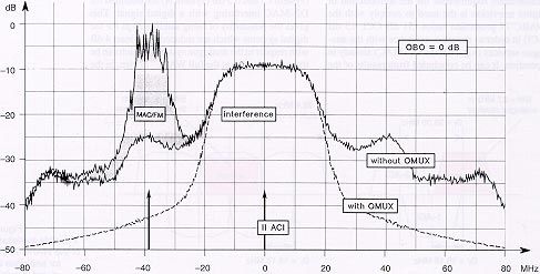
Recent studies in the framework of the HD–SAT formance in terms of satellite power efficiency, Figure 4
project seem to indicate that adaptive non–linear since near–constant–envelope modulations can be FDM carrier
equalization of OFDM signals could significantly adopted (e.g., QPSK, 8PSK), allowing the TWTA configuration.
reduce these Eb/No penalties, but at the cost of
doubling (at least) the OFDM demodulator com-
30 MHz
plexity, which is already at the limit of today’s
technology. 1 2 3 4
The use of FM modulation combined with OFDM/
Df Rs ’
TC–16QAM would provide an interesting solu-
N=4
tion for satellite transmissions, allowing operation
with the TWTA at saturation, thanks to the
N=2 Df
constant envelope of the FM signal. A common
OFDM demodulator with 7 MHz bandwidth could
then be used for terrestrial, cable and satellite re-
ceivers, the latter with an additional FM demodu- 1 2
EBU Technical Review Summer 1993 37
Cominetti et al.to operate close to saturation. However, this solu- same total bit rate Ru = N Ru’. The degradation in-
tion implies operational constraints because all the cludes the effects of linear and non–linear distor-
service components must be conveyed to the site tions, power losses with respect to the TWTA satu-
where the multiplex is assembled and the signal ration power, and mutual interference between
up–linked. carriers.
For two digital carriers (N = 2) at 17 Mbit/s, the
The second approach (FDM) is more flexible as re- FDM approach requires a 2.3–dB increase of satel-
gards the up–link requirements and could be ad- lite power with respect to a 34–Mbit/s TDM
vantageous in terms of commonality for direct dis- single–carrier system, for the same service avail-
tribution of satellite digital signals in cable ability. The satellite power should be increased by
networks, with a channel bandwidth of 7 to 8 MHz. 3.3 dB in the case of two carriers at 22.5 Mbit/s (45
However this approach inherently does not pro- Mbit/s total bit–rate). In the case of four carriers (N
vide a resulting signal having a constant envelope. = 4) at 8.5 Mbit/s per carrier, the power penalty is
It is then necessary to operate the TWTA in a 5.8 dB.
quasi–linear region, which implies reducing the
system power efficiency. In addition, the future For an assigned satellite power, the Eb/No degrada-
evolution from multi–programme television to tion of the FDM approach could be overcome by
HDTV would become more complex, as it would a corresponding increase of the receiving antenna
be necessary to change the transmitted bit–rate and diameter (i.e., an additional 30%, 46% and 95%,
to merge FDM channels. respectively for the three cases considered above).
The two approaches have been simulated on the From these results it is possible to conclude that the
same satellite channel as described in Section 3.3, TDM approach to access the satellite transponder
assuming a 38.4–MHz OMUX filter. 2 and 4 carri- is significantly more power–efficient than the
ers (denoted by N), with QPSK rate 3/4 (system FDM approach, expecially when four FDM digital
A), have been allocated per transponder. Each sig- carriers are considered. In this case, TDM is partic-
nal carries a bit–rate Ru’ = (Ru / N), where Ru is the ularly suitable for direct–to–home services using
total useful bit–rate in the transponder. As shown small receiving antennas (50 – 60 cm). On the oth-
in Fig. 4, to maintain an interference level on the er hand, FDM at 4 x 8.5 Mbit/s could be interesting
adjacent channels which is similar to that of a for multi–programme television distribution to
single–carrier system at Rs= 30 Mbaud, the –3 dB cable network head–ends, equipped with large re-
RF bandwidth of the FDM ensemble has been set ceiving antennas, because each FDM carrier, with
to 30 MHz. Therefore the N carriers are spaced by QPSK 3/4 modulation, can be distributed in
Df = (Rs–Rs’)/(N–1), where Rs’ is the symbol rate 8–MHz cable channels. This would allow simple
of each FDM carrier. frequency conversion without the need of re–mod-
ulation (see Section 7).
After an optimisation process, a global input back–
off (IBO) of 4 and 6 dB, corresponding to 0.5 and 5. Interference considerations
1 dB OBO on the TWTA, have been adopted for N and transmission capacity
= 2 and 4, respectively. The corresponding input
back–off per carrier is (IBO+ 10 log N) dB. 5.1 Low and medium power
satellites
Table 3 gives the Eb/No degradation at BER = In Europe, Eutelsat II telecommunications satel-
2x10⁻⁴ (after Viterbi decoding) of the FDM ap- lites carry 36/72 MHz transponders (see the chan-
proach, compared to the TDM approach at the nel matrices in Fig. 5), in the Ku–band (14/11
GHz), and they are suitable for digital transmis-
sions at 60/120 Mbit/s with QPSK modulation. On
Total Eb/No degradation () (dB) the 72 MHz transponders, TDMA telecommunica-
bit–rate
bit rate tion services at 120 Mbit/s are in regular operation.
Table 3 (Ru)
N = 2 carriers N = 4 carriers The 36 MHz transponders are particularly suitable
Eb/No degradation (Mbit/s)
of FDM compared for the distribution of digital television for supra–
to TDM 34 2.3 (2x17 Mbit/s) 5.8 (4x8.5 Mbit/s) national coverages. A transmission capacity of 45
(QPSK 3/4, satellite 38 2.4 (2x19 Mbit/s) 6.1 (4x9.5 Mbit/s) Mbit/s or 60 Mbit/s can be used with QPSK 3/4
channel, BER = 41 2.7 (2x20.5 Mbit/s) 7.9 (4x10.25 Mbit/s)
(System A) or TC–8PSK 2/3 (System C), respec-
2x10⁻⁴ after Viterbi tively. The modulation and channel coding tech-
45 3.3 (2x22.5 Mbit/s) –
decoding). niques described in Section 3.2. (with minor modi-
38 EBU Technical Review Summer 1993
Cominetti et al.fications), combined in a flexible bit–rate modem,
have been extensively studied and adopted in the Df = 41.6 MHz BW = 36 MHz
European RACE Flash–TV project [8], which is
focused on HDTV contribution links via 36 MHz
transponders in Ku band, from transportable up–
link stations. This digital system is now being im-
plemented.
Astra satellites 1A, 1B, 1C, introduced by the So-
ciété Européenne des Satellite (SES), carry trans-
ponders with 26 MHz bandwidth. The usable
transmission capacity is then about 34 Mbit/s and
44 Mbit/s, depending on the transmission system
BW = 36 MHz
(A or C). The capacity could be further increased
to about 41 Mbit/s and 55 Mbit/s in the new gen-
eration Astra satellites (1D and 1E), operating in Df = 83.3 MHz
the 11.7–12.5 GHz band (19.2°E), which will
carry transponders of 33 MHz bandwidth [10]. An
additional C/N degradation of about 0.4 dB can be
expected if the bit–rate is increased from 41 to BW = bandwidth for 0.5 dB typical attenuation
45 Mbit/s (system A), in order to have the same
bit–rate as are used on the Eutelsat and BSS satel-
lites. RAI studies (see Appendix 1) that, with PSK mod- Figure 5
ulations and raised–cosine spectrum shaping Eutelsat II channel
5.2 BSS satellites in the WARC’77 (roll–off 0.4), a maximum symbol rate of matrix in the 11 GHz
Plan 30 MBaud is usable in the WARC’77 channels. band
The corresponding useful bit–rates are 45 Mbit/s (36 and 72 MHz
In the case of BSS satellites at 12 GHz and 60 Mbit/s for modulation systems A and C, re- transponders).
(WARC’77), the 27 MHz channel bandwidth is spectively. The CCI protection ratios are signifi-
practically defined by the receiver, while the satel- cantly lower than the 31 dB required by the
lite OMUX is wider (usually about 50 MHz) since WARC’77 Plan. The ACI protection ratios are at
the five channels provided by the satellite are sepa- the limits of the WARC’77 requirements (i.e., 15
rated from each other by about 77 MHz (4 x 19.18 dB) in the case of digital signals at 30 MBaud inter-
MHz). The channel matrix is shown in Fig. 6. A fering with analogue FM, while margins of 4 dB
fundamental requirement for the introduction of (system C) and 6.5 dB (system A) are obtained for
digital television is the need to comply with the D2–MAC interfering with a digital signal. This
WARC’77 protection ratios (31 dB CCI, 15 dB gives the possibility of using satellite eirps for the
ACI) in order to ensure coexistence with the ana- digital systems which are reduced by at least 4 dB
logue services (e.g. in PAL, D2–MAC) already in with respect to the analogue systems, which can be
operation. It can be concluded from results of the transmitted today at the full WARC’77 eirp. In the
BW = 27 MHz in BW = 30 MHz in
the analogue receiver 38.4 MHz the digital receiver
(OMUX for digital)
Df = 38.36 MHz
wanted 2–ACI wanted
1–ACI
Figure 6
Possible exploitation
of the WARC’77 Plan
Df’ = 19.18 MHz Df’ = 19.18 MHz for analogue and
digital television.
Analogue signals Digital signals
EBU Technical Review Summer 1993 39
Cominetti et al.Video coding Hybrid DCT To allow interference protection on the second ad-
jacent channels (spaced by 38.36 MHz), while op-
Table 4 Modulation QPSK + rate 3/4 erating the TWTA at saturation, a satellite OMUX
Example of digital inner code filter with about 38.4 MHz bandwidth at –3 dB
multi–programme (see Section 3.2.) should be adopted. Fig. 7 shows
Useful bit–rate (including RS) 45 Mbit/s
TV/HDTV system for the spectrum of a 30 Mbaud PSK signal (2–ACI)
12–GHz satellite Error protection RS(255,239) 3 Mbit/s interfering with a D2–MAC/FM signal, with and
broadcasting without sidelobe suppression by the OMUX.
(Italy, climatic zone K). HDTV service
video 40 Mbit/s
audio 0.64 Mbit/s
6. Satellite digital
(5 MPEG–Audio multi–programme
stereo channels) television and HDTV
data 1.36 Mbit/s
(teletext, service information, On the basis of the results of Sections 3 and 5,
conditional access) QPSK associated with a rate 3/4 inner code is as-
Multi–programme TV service
sumed as the modulation system at a gross bit–rate
of 45 Mbit/s, including RS(255,239) error protec-
4 EDTV programmes 11 Mbit/s per prog.
tion. Examples of possible service configurations
8 STDTV programmes 5.5 Mbit/s per prog.
of the multiplex include one HDTV programme,
Required C/N ratio (in 30 MHz) four EDTV programmes or eight SDTV pro-
for high–quality pictures 9.6 dB grammes. Table 4 gives, as an example, the main
(including 2.5 dB margin) characteristics of a possible digital multi–
programme TV/HDTV system based on this ap-
Receiving antenna diameter re-
quired for high–quality pictures 60 cm proach. High picture quality for the various ap-
in 99.7% of worst month plications (SDTV, EDTV, HDTV) should be
Service area: 54 dBW eirp con- achievable for most production material at the bit–
tour
rates of 5.5 MBit/s, 11 MBit/s and 45 MBit/s, re-
spectively (see Section 3.1.).
future, in a fully–digital scenario, all the eirps of
Figure 7 the Plan could be further reduced and the signifi- Service availability depends on the sensitivity to
QPSK signal at 30 cant CCI and ACI protection ratio margins could errors of the picture coding algorithm and of the
MBaud interfering be exploited to achieve greater flexibility in the multiplex, and on the noise margin provided by the
with a MAC/FM signal
in the WARC’77 Plan.
coverage area design. transmission system. For the EU–256 HDTV co–
dB
0
–10
Power
–20
–30
–40
–50
–80 –60 –40 –20 0 20 40 60 80 MHz
Frequency offset
40 EBU Technical Review Summer 1993
Cominetti et al.eirp at Antenna diameter (cm) giving
Satellite Orbital beam Number of high–quality service
position centre channels for 99.7% of worst month
(dBW)
Beam centre –3 dB contour
TDF1 & 2, TV–SAT 19°W 64–65 5 40 40
High TELE–X 5°W 63 2 40 40
power
HISPASAT 31°W 58 5 40 50
EUTELSAT B (Note 1) 13°E 57 14 40 60
ASTRA (Note 2) 1D, 1E 19.2°E 53.5 2x18 65 90 Table 5
Medium EUTELSAT II (F1,2,3,4) 13, 10, 16, 7°E 51.5 4x9 80 110
power Characteristics and
EUTELSAT II F6 13°E 49.5 18 100 140 performance of high
(Hot bird) and medium–power
satellites for digital
Note 1: Project under examination
TV/HDTV broadcast–
ing and distribution
Note 2: The receiving antenna diameter refers to 41 Mbit/s, QPSK 3/4 signals on 33 MHz transponders (45 Mbit/s, QPSK 3/4).
decs a maximum BER of 2x10⁻⁴ at the demodula- natively, TC–8PSK 2/3 at 45 Mbit/s can be used,
tor output (after Viterbi decoding), ensures high– but with a penalty of about 1.5 dB C/N with respect
quality pictures after RS(255,239) error correction to QPSK 3/4.
(see Section 3.2.). At BER of 2x10⁻³, correspond-
ing to a further C/N reduction of about 1 dB, the Table 5 compares the characteristics and perfor-
system synchronization and service continuity are mances of high–power and medium–power satel-
lost. lites, currently in operation or planned for future
introduction, in terms of capacity (number of chan-
The ideal service continuity target (outage time) nels) and eirps on the axis. The last two columns
for digital TV/HDTV systems at 11–12 GHz give the antenna diameter for high–quality recep-
would be 99.9% of the worst month (correspond- tion (99.7% of the worst month) of TV/HDTV at
ing to about 40 minutes of outage time); this is cur- 45 MBit/s QPSK 3/4, at the beam centre and at the
rently achievable by conventional FM/TV sys- –3 dB contour. The receiving antennas are very
tems. In the digital system considered in the small (40 to 60 cm) for high–power satellites at 12
example of Table 4 the target for high–quality pic- GHz. Eutelsat B at 13°E should provide 14 chan-
ture availability is set at 99.7% of the worst month. nels, potentially usable for direct–to–home broad-
Taking into account the typical rain attenuation casting of up to 56 (14 x 4) EDTV programmes or
statistics at 12 GHz in Italy (climatic zone K) a re- 14 HDTV programmes. In the case of medium–
ceiving antenna of 60 cm would be sufficient for power satellites, Eutelsat II F–6 (Hot Bird) will
high–quality HDTV or multi–programme EDTV/ provide up to 72 (18 x 4) EDTV programmes or 18
SDTV reception, for 99.7% of the worst month HDTV programmes, receivable with 100 to
(BER = 2x10⁻⁴, C/N = 9.6 dB in 30 MHz, 54 dBW 140–cm antennas. Eutelsat II F1, 2, 3, 4, currently
eirp service area contour, receiver NF = 1.5–1.2 in operation, could provide a total of 144 (4 x 9 x
dB, 2.1 dB C/N loss because of rain attenuation 4) EDTV programmes (or 36 HDTV pro-
from 99 to 99.7% of the worst month). Under these grammes), but from four different orbital posi-
conditions 99.9% service continuity (BER = tions. A similarly impressive transmission capac-
2x10⁻³) is practically achieved, taking into ac- ity will be made available by future Astra 1D, 1E
count also the quite large implementation margins satellites, from a common orbital position
assumed (i.e. 2.5 dB). (19.2°E) in the BSS band (11.7–12.5 GHz). The re-
quired receiving antennas will range from 65 to 90
The same TV/HDTV system at 45 Mbit/s with cm.
QPSK 3/4 is suitable for use on medium–power
satellites with 36 MHz channel bandwidth. In the This evolutionary scenario of satellite television,
case of Astra 1D, 1E, with 33–MHz transponders, stimulated by the introduction of digital tech-
the bit–rate should be limited to 41 Mbit/s (see Sec- niques, is expected to be a reality before the end of
tion 5.1.). If a bit–rate of 45 Mbit/s is adopted, the the century. In a longer–term perspective, digital
antenna diameter should be increased in order to W–HDTV could be introduced in the 21.4–22
balance the signal degradation (typically 0.5 dB GHz band, with the same system concepts pro-
C/N) due to the bandwidth limitation [10]. Alter- posed for use in the 11–12 GHz band. Early studies
EBU Technical Review Summer 1993 41
Cominetti et al.[6] have demonstrated the possibility of broadcast- community receiving installations serving single
ing, in the 21.4–22 GHz band, 12 W–HDTV pro- buildings.
grammes per service area at 70 Mbit/s, by exploit-
ing the two polarizations. However, due to the The adoption of a unique modulation scheme opti-
severe propagation conditions at 21.4–22 GHz, a mised for the two transmission media, satellite and
digital HDTV system exhibiting abrupt failure cable, is practically impossible. In effect, the satel-
characteristics may not be able to provide the re- lite channel is basically non–linear and power lim-
quired service availability without a penalty on the ited, but does not suffer from stringent bandwidth
satellite transmit power. A method to extend ser- limitations; cable channels are linear and allow rel-
vice continuity, without increasing the satellite atively high S/N ratios, but are band–limited and
power, has been developed by the CCETT. This are currently affected by echoes and other distor-
advanced system is based on the adoption of lay- tions. However, a common modulation system
ered modulation in conjunction with layered pic- could probably be adopted for terrestrial broad-
ture coding and layered channel coding. It pro- casting channels and for cable networks.
vides graceful degradation from HDTV quality, In Italy, the distribution of satellite signals in cable
achievable for most of the time, to conventional receiving installations could be done in the 8–MHz
television quality during deep rain fades. channels of the UHF bands, and/or in the extended
superband (230 to 470 MHz) with 8 MHz or 12
MHz channel spacing, as foreseen for distribution
of D2–MAC and HD–MAC.
7. Distribution of digital
TV/HDTV signals in cable At the network head–end, various technical ap-
networks proaches could be chosen to adapt the signal re-
ceived from the satellite to the cable channels. For
Satellite television broadcasting, although primar- example:
ily focused on direct–to–home reception, requires a) demodulation, error correction, demultiplexing
signal distribution via large cable networks and of each service component, conversion to PAL/
Dr. Mario Cominetti graduated in physics at Turin University and joined the Research Centre of RAI–
Radiotelevisione Italiana in 1963. He is now Head of the RF Technologies Division where he is con-
cerned with advanced digital transmission systems.
He is Chairman of EBU Sub–group V2 (Data broadcasting) and a member of the European Working
Group on Digital Television Broadcasting (WGDTB).
Dr. Cominetti is an active contributor to the studies of the CCIR and in recognition of this activity he
was awarded the Diplôme d’Honneur 1989.
Mr. Michele Visintin graduated in electronics engineering at
Turin Polytechnic in 1987. He joined the Research Centre of RAI–
Radiotelevisione in 1988 where he is involved in the analysis of
digital communications systems and computer simulations.
Dr. Alberto Morello graduated in electronic engineering at Turin Polytechnic in 1982 and took his doc-
torate degre in 1987. He joined the Research Centre of RAI–Radiotelevisione Italiana in 1984 and is
now in charge of the digital transmission group of the Special Technologies Laboratory. He is engaged
in research on digital modulation and coding techniques for audio, data and television, and high–
definition television transmission and broadcasting via satellite.
Dr. Morello is a member of several groups in the EBU and CCIR and has authored a number of techni-
cal and scientific articles relating to his studies.
42 EBU Technical Review Summer 1993
Cominetti et al.SECAM for distribution in AM/VSB (short
term solution);
dB ns
b) demodulation, error correction of the digital 25
signal, digital remodulation on a single cable 16
channel or in two merged channels; 26
Attenuation
Group delay
8
c) demodulation, error correction, demultiplexing
27
of the digital service components and re–
0
assembly of reduced bit–rate multiplexes, digi-
28
tal re–modulation on separate cable channels;
–8
d) in the case of FDM satellite transmission at 4 x 29
8.5 Mbit/s (see Section 4.), the four digital carri- –16
ers can simply be filtered and frequency con- 30
verted for distribution into four independent 8 –30 –20 –10 0 10 20 30 MHz
MHz cable channels. Frequency offset
Suitable digital modulations for cable networks Figure 8
Simulation results on the performance of 16QAM
are 16QAM (spectral efficiency M = 4 bit/s/Hz), Typical distribution
at 34 Mbit/s with a blind adaptive equalization network
32–QAM (M = 5 bit/s/Hz), and 64QAM (M = 6 bit/ (4–tap transversal filter) [4] have demonstrated the characteristics.
s/Hz), or their trellis–coded versions (M–1 bit/s/ good performance of this system in the presence of
Hz) with Viterbi decoding. They can be associated typical linear distortions (see Fig. 8) introduced by
with single–carrier (SC) modulation with adaptive a community antenna system. Fig. 9 shows the
equalization in the receiver or with multi–carrier 16QAM constellation with and without adaptive
OFDM modulation. equalization.
The maximum bit–rate in a single 8 MHz channel, 8. Transmission experiments
using 32QAM (M = 5 bit/s/Hz) with sharp roll–off
The availability of EU–256 codecs and of a trans-
(0.16), is of the order of 34 Mbit/s and the required
portable feeder–link station for the Olympus satel-
C/N ratio (in 8 MHz) is about 27 dB (including 2
lite at 12 GHz has allowed the RAI Research
dB implementation margin and 2 dB linear distor-
Centre to carry out several transmission experi-
tion margin after equalization).
ments of digital television at 17 Mbit/s and 34
MBit/s, and HDTV at 70 and 45 Mbit/s, during the
Two 8–MHz channels could be used to convey a past few years. The large–scale HDTV transmis-
single digital signal at 45 Mbit/s (approach b) or sions carried out during the Football Worldcup
two independent signals at 22.5 Mbit/s (approach (Italia’90) demonstrated the reliability and the
c), requiring 23 dB C/N in 16 MHz with 16QAM technical and operational feasibility of a satellite
modulation. In 12–MHz channels, 32QAM at 45 point–to–multipoint digital transmission system
Mbit/s could be used, requiring a C/N (in 12 MHz) for high–quality HDTV programmes. HDTV
of 26.5 dB (with 4 dB margins). transmissions at 45 Mbit/s, carried out by Retevi-
Figure 9
Use of equalization on
a domestic distribution
network carrying 34
Mbit/s 16QAM signals
(constellation
diagrams after
before equalization after equalization (5 taps) demodulation).
EBU Technical Review Summer 1993 43
Cominetti et al.sión via Eutelsat II during the Olympic Games low cost, are therefore the key to the future
(Barcelona’92), confirmed these results. Recently, introduction of satellite multi–programme televi-
in the framework of the RAI participation in the sion services, at various quality levels: EDTV and
HD–SAT project, the feasibility of a complete SDTV, including the evolution to HDTV. Broad-
HDTV chain for transmission at 70 Mbit/s (QPSK casters, satellite operators and receiver manufac-
rate 2/3) via the 30/20 GHz payload of the Olym- tures are actively developing common plans in this
pus satellite has been demonstrated. Further field direction. A suitable transmission technique to
trials are planned using Olympus at 12 GHz, in co– cope with the power constraints of satellite chan-
operation with the European Space Agency nels is based on QPSK modulation, with rate 3/4
(ESA), to assess the performance of a digital trans- FEC (forward error correction) with Viterbi de-
mission system at 45 Mbit/s with TC–8PSK rate coding. This technique has minimal demodulation
2/3. performance degradations and reasonable receiver
complexity for the consumer market. Medium–
power satellites are the ideal channels for the rapid
9. Conclusions
introduction in Europe of these new services, al-
The progress of digital technology offers concrete lowing maximum exploitation of the transponder
perspectives for digital television on different dis- capacity. It is then possible to foresee, by the end
tribution media (satellite, terrestrial channels, of the century, a significant evolution in satellite
cable networks and B–ISDN). Advanced digital television from the analogue to the digital world,
techniques for picture and sound coding, channel with progressive integration of services provided
coding and modulation, have proved their efficien- by satellite channels and terrestrial digital net-
cy and reliability in several transmission experi- works. The need for harmonisation and com-
ments, and are now entering the VLSI imple- monality in source coding and multiplexing tech-
mentation phase. Multimedia applications of niques for use on the various delivery media is the
digital video technology are already becoming a key factor for the evolution towards this future sce-
reality. The availability of digital techniques, at nario.
Appendix 1
Interference compatibility of digital signals in the WARC’77 Plan
Extensive studies have been focused on the identi- quirements defined for interference to (and from)
fication of the maximum symbol rate (correspond- the reference PAL/FM system.
ing to the –3 dB spectrum occupancy) for QPSK
and 8PSK transmission in the12–GHz channels of Particular attention was paid to the spectrum
WARC’77, while still fulfilling the interference re- spreading of the digital signal at the output of the
quirements regarding analogue systems (PAL, satellite TWTA, operating close to saturation. In
MAC) requiring protection ratios of 31 dB (CCI) order to reduce the interference to channels at
and 15dB (1–ACI). ±38.36 MHz, a satellite output filter (OMUX) of
38.4 MHz bandwidth (at –3 dB) has been adopted.
The protection ratio PR is defined as “the power ra- Fig. A.1 gives the protection ratios at the visibility
tio between the wanted and interfering unmodu- threshold obtained for the case of QPSK, at differ-
lated carriers giving a pre–defined impairment in ent symbol rates, interfering with a PAL/FM sig-
the wanted signal”. The Plan was defined assum- nal. Since all the curves with symbol rates up to 30
ing as a reference a PAL/FM wanted signal (fre- MBaud are contained in the template given in Ap-
quency deviation 13.5 MHz/V, receiving filter pendix 30 of the Radio Regulation (dotted line),
bandwidth 27 MHz), and a “just perceptible” im- the value of Rs = 30 MBaud represents the maxi-
pairment, corresponding to about grade 4.5 of the mum symbol rate usable for digital transmission in
5–grade scale of CCIR Recommendation 500–4. the WARC’77 channel. The curves have been ob-
Other types of modulation are allowed (even with tained by computer simulations, measuring the re-
a receiving filter bandwidth wider than 27 MHz), quired protection ratio to achieve a weighted sig-
provided that they fulfill the protection ratio re- nal to interference ratio of 54 dB for the PAL signal
44 EBU Technical Review Summer 1993
Cominetti et al.You can also read