Cement and Concrete Research - EPFL
←
→
Page content transcription
If your browser does not render page correctly, please read the page content below
Cement and Concrete Research 143 (2021) 106368
Contents lists available at ScienceDirect
Cement and Concrete Research
journal homepage: www.elsevier.com/locate/cemconres
Capillary flow in UHPFRC with synthetic fibers, under high tensile stresses
Amir Hajiesmaeili *, Emmanuel Denarié
Maintenance and Safety of Structures, Ecole Polytechnique Fédérale de Lausanne, Station 18, GC A3 398, CH-1015 Lausanne, Switzerland
A R T I C L E I N F O A B S T R A C T
Keywords: A novel Ultra High-Performance Fiber Reinforced Concrete (UHPFRC) mix with synthetic fibers and a low clinker
Capillary absorption matrix, henceforth referred to as PE-UHPFRC, has been developed for structural applications. It exhibits a high
UHPFRC tensile elastic limit above 7 MPa, a tensile strength of more than 10 MPa, and a very high tensile hardening
PE-UHPFRC
domain of above 3.5%. In order to effectively use this material, its protective properties have been investigated
UHMW-PE fibers
Tensile response
on the basis of the effect of tensile deformation and subsequent cracking on water transport properties, for a wide
Crack characteristics range of tensile strain. A special setup was developed to measure the capillary absorption of liquids while the
specimen is under tension. The results show a considerable reduction in capillary absorption in case of PE-
UHPFRC compared with Strain Hardening Cement-based Composites (SHCC). Moreover, the results highlight
the considerable effect of the onset of cracking on capillary absorption.
1. Introduction pressure gradient. Consequently, it is not entirely representative as
structures made from cementitious materials are rarely saturated and
The ever-increasing demand of society for the build environments on exposed to strong pressure gradients in the building environment
one hand and the limited material resources, on the other hand, have (excluding underground and offshore structures). Hence, sorptivity is a
promoted the implementation of high and ultra-high-performance ma more realistic property to describe the liquid transport and durability of
terials towards sustainability during the last few decades. Meanwhile, cementitious materials in structural applications were capillary flow
UHPFRC has successfully gained the ground and has proved its potential prevails. There are two general approaches to model and analysis the
to be one of the solutions to contain the explosion of the costs (economy sorptivity of cementitious materials in literature, which both yield a
and environment) along with its numerous applications [1–3]. linear relationship between capillary absorption and the square root of
Continuing this trend, PE-UHPFRC is developed with 75% reduced time. The first approach is based on an extension of Darcy’s law to un
environmental impact compared to conventional UHPFRC mixes by saturated porous media [5] and the second approach is based on the
replacing the steel fibers with Ultra High Molecular Weight Poly Lucas–Washburn equation [6,7], which describes the dynamic flow
ethylene (UHMW-PE) ones and replacing 50% of the clinker with equation of liquids in a capillary tube. The latter approach is more
limestone fillers [4]. The high tensile elastic limit above 7 MPa, tensile employed to describe the capillary absorption of cracked cementitious
strength of more than 10 MPa, and tensile deformation capacity of more materials [8–10] in which the sorptivity corresponds to the square root
than 3.5% make the newly developed UHPFRC well adapted for struc of crack width. Furthermore, Zaccardi et al. [11] reported a better
tural applications. In order to effectively use this material, its protective correlation between the water capillary absorption, and the fourth root
properties need to be investigated on the basis of the effect of tensile of time for normal concretes with ordinary Portland cement and
deformation and subsequent cracking on water transport properties and pozzolanic Portland cement.
accordingly on the durability of the material. Different measurements for evaluating the transport properties, such
Deterioration mechanisms in cementitious materials are principally as capillary absorption, gas penetration, and liquid penetration were
caused by insufficient protection followed by ingress of catalysts like carried out on undamaged UHPFRC specimens [12–18], which all show
water and aggressive agents in the material. Sorptivity and permeability a considerable improvement compared to ordinary and high strength
are used as a measure for liquid transport properties and thereupon for concretes. Roux et al. [18] showed that the capillary absorption of
the durability of cementitious materials. Permeability relates the UHPFRC is over ten times less than that of conventional concretes.
movement of moisture through a saturated porous medium under a Furthermore, they reported that the air permeability and chloride
* Corresponding author.
E-mail addresses: Amir.Hajiesmaeili@epfl.ch (A. Hajiesmaeili), Emmanuel.Denarie@epfl.ch (E. Denarié).
https://doi.org/10.1016/j.cemconres.2021.106368
Received 16 September 2019; Received in revised form 3 January 2021; Accepted 8 January 2021
0008-8846/© 2021 Elsevier Ltd. All rights reserved.
A. Hajiesmaeili and E. Denarié Cement and Concrete Research 143 (2021) 106368
diffusion coefficient of UHPFRC are at least two orders of magnitude less Table 1
than that of C30 and C80 concretes. Tam et al. [16] found that the water Mix proportions of PE-UHPFRC (mix PE21).
permeability coefficient of UHPFRC is lower than that of normal con Components (kg/m3)
crete by one or two orders of magnitude. The resistance of UHPFRC to
Cement 508
the penetration of chloride ions was investigated by many researchers Silica fume 118
[3,14,18] and it was shown that UHPFRC has a much higher resistance Betocarb®-HP SL 170
to penetration of chloride ions than ordinary concretes and that the Betoflow®-D 389
depth affected from the surface of exposed areas is remarkably lower in Quartz powder 223
Fine sand 525
UHPFRC. Furthermore, numerous studies have confirmed the durability Water 165
of structures built with UHPFRC after several years of exposure to severe HRWRA 27
conditions [19–23]. These features are attributed to the homogenous Ca(NO3)2 11
and highly dense microstructure of UHPFRC. UHMW PE fibers (Dyneema® SK99) 19.6
At service state, structural elements experience different levels of
mechanical loading under both autogenous (eigenstresses) and exoge
nous actions (climate conditions, live loads, deadweight, accidental
actions, fire, etc.), well documented in the literature [24–26]. However,
only a few notable studies were carried out on the effects of damage on
the transport properties of UHPFRC [24–30]. Wang et al. [26] studied
the influence of imposed compressive stresses on capillary absorption of
UHPFRC and found that the absorbed water mass increased by a factor
of two when the specimens were loaded up to 50% of their compressive
strength. The effect of tensile stresses on capillary absorption was
investigated by Wittmann et al. [24] and it was shown that the capillary
absorption is significantly increased if the material is subjected to tensile
stresses higher than 50% of its tensile strength. Accordingly, Wang et al.
[25] reported that the sorptivity of UHPFRC increases by 30%, 45%,
77% and 95% for load levels of 50%, 60%, 70% and 80% of its splitting
tensile strength, respectively.
ECC (Engineered Cementitious Composite) [31], SHCC [32] and
HSHDC (High Strength, High-Ductility Concrete) [33] are classes of
Fig. 1. PSD of the components and final mix.
synthetic fiber-reinforced cementitious composites with high tensile
deformation capacity. Although from a mechanical properties point of
view, HSHDC is the closest to PE-UHPFRC, to the best of authors’ materials.
knowledge, no extensive research has been reported in the open litera
ture on transport properties of this material. However, the durability of 2. Material design
ECC and SHCC, which are designed to limit the ingress of potentially
deleterious substances by controlling cracks width, were investigated in A newly developed UHPFRC mix, named “PE-UHPFRC” (ref. mix
terms of transport properties, as a function of different crack width and PE21), was used for the present study. The Embodied Energy (EE) of this
strain levels by several researchers [34–43]. The results show that the mix is reduced by 75% with respect to that of current UHPFRC mixes for
water permeability under pressure is very much linked to the crack structural applications, with steel fibers. In PE-UHPFRC mixes, the steel
features and cracking patterns. Regardless of the material type (SHCC, fibers are fully replaced by UHMW-PE ones and 50% volume of the
normal concrete and UHPFRC), the permeability to liquids under pres clinker is replaced by limestone fillers. Considering that the optimiza
sure starts increasing at a much faster rate with increasing crack width tion of packing density and low w/fines ratio are the keys for obtaining
after 0.05 to 0.1 mm [30,40,41]. However, the capillary water absorp Ultra high-performance cementitious composites, a generalization of the
tion in SHCC specimens was found to increase drastically by increasing Compaction-Interaction Packing Model (CIPM) model [46] was derived
the strain in the specimens even before a crack opening of 0.1 mm [39]. and applied to optimize the mixture design [4]. Six different powders
Investigations by means of neutron radiography showed that pre- including cement CEM I 52.5 HTS Lafarge, two types of limestone filler
existing microcracks subjected to capillary absorption become water- of different gradings: Betoflow D® and Betocarb SL® (OMYA), white
filled only after a few minutes [44]. Furthermore, increasing strains silica fume from SEPR (BET = 14 m2/g), quartz powder and fine quartz
from 0 to 0.5% results in almost a 72% higher water capillary absorption sand (d50 = 0.250 mm) were used in the mixes. Moreover, a modified
[42]. Although the crack width plays an important role on the capillary Polycarboxylates-based HRWRA was used to maintain flowability and
absorption of cementitious materials, its effects have been under rheology of the mixture at the very low w/fines ratio of 0.146. The
estimated in the aforementioned studies as the capillary absorption was composition of the PE-UHPFRC mix is given in Table 1. Moreover, Fig. 1
determined after unloading the specimens. shows the particle size distribution (PSD) of the powders used and of the
In this study, an original test setup was developed in order to mea mix. The packing density of the final mix was 0.81 based on the
sure the capillary absorption of materials under tensile loading. The generalized CIPM, by using a compaction index of 9 for the calculations.
water sorptivity of tensile specimens made from PE-UHPFRC was
investigated over a wide range of tensile deformation with the help of Table 2
the developed setup. Afterwards, the specimens were unloaded and the Geometry and mechanical properties of PE Fiber.
capillary absorption of the same specimens was determined in accor Fiber properties Values
dance with EN13057:2002 standard [45], in order to compare the
Diameter df (μm) 12
sorptivity under load and after unloading. As the cracking behavior Length lf (mm) 6
highly affects the capillary absorption, Digital Image Correlation (DIC) Nominal strength (MPa) 4100
was used to analyze the crack characteristics including crack pattern and Nominal Young’s modulus (GPa) 155
width and investigate their effect on sorptivity. Finally, the results were Elongation at break (%) 3.5
Specific weight (kg/m3) 980
put into perspective with existing experimental data on related
2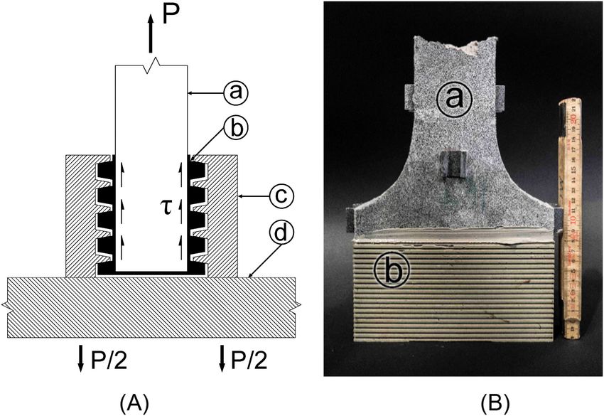
A. Hajiesmaeili and E. Denarié Cement and Concrete Research 143 (2021) 106368
the other, in a systematically repetitive procedure to obtain reproducible
fiber orientation and distribution. The lower internal face of the molds
was covered with a Controlled Permeability Formliner (CPF) - Zem
drain® sheet to avoid the water repellent effect of demolding oil. In
order to avoid surfacing, the top surface of the specimen was covered
immediately after pouring with a Zemdrain® sheet attached to a wood
panel to guarantee a flat and uniform upper surface without air voids,
after setting. Regarding the use of Zemdrain® sheets on the UHPFRC
surfaces, it should be noted that according to [49], using these sheets
had a negligible effect on the air permeability of concretes with a w/c
ratio of 0.43. It can thus be assumed that their effect on the mechanical
and transport properties of the UHPFRC skin are negligible. Moreover,
Fig. 2. Dumbbell specimen geometry (dimensions in mm). the lateral internal faces of the molds along the shoulders were covered
with 1 mm thick deformable tape to prevent eigenstresses and restrained
Ca(NO3)2 was employed in the form of a water-soluble compound in shrinkage cracks at an early age. The specimens were kept sealed after
order to optimize the performance of the superplasticizer and reduce its casting for 2 days at room temperature of 20 ± 5 ◦ C. Thereupon
dosage and thus the air content. At fresh state, the air content and the demolding, the specimens were stored at room temperature of 20 ± 5 ◦ C
specific weight of the material were 4.5% and 2215 kg/m3, respectively. under 95% RH. Before testing at 28 days, the specimens were washed
Furthermore, the flow was 48% after ASTM C1437 [47], with a final with soap, to ensure removing of any fat with a water repellent effect.
diameter after 25 blows of 150 mm. This was followed by a drying process at 50 ◦ C up to a constant weight.
The fibrous mix consisted of 2% vol. 6 mm long, chopped UHMW-PE Eventually, the specimens were stored in the laboratory at ambient
fiber type SK 99 from DSM Dyneema®. The mechanical properties and conditions (20 ◦ C under 50% RH) for at least 12 h.
the geometry of these PE fibers are given in Table 2.
3.2. Tensile test
3. Experimental procedure
In order to avoid as far as possible bending effects during the test, an
3.1. Specimen design and preparation optimized set-up was used with: (1) a stiff (4 columns) testing machine,
(2) fixed/fixed support conditions for the specimen, and (3) a highly
An original dumbbell specimen was designed with a thickness of 30 accurate alignment of the specimen thanks to a special procedure to link
mm representative of that found in numerous applications of UHPFRC, it directly to the machine without clamping. The dumbbell specimens
either cast-on-site for rehabilitation or in structural uses with thin pre were attached to the testing set-up by means of the “gluing without
cast ribbed members. The specimen had 290 mm length with a constant bonding” approach proposed by [50], and applied to dumbbell specimen
cross-section, with a width of 80 mm, on which three capillary chambers by [51], Fig. 3. A steel shoe formed of plates with indented internal faces
were installed (Figs. 2 and 5). The total length of the specimen was 750 (c) on Fig. 3, was used as a form to cast resin indentations glued to the
mm. In order to limit as far as possible stress concentrations, Neuber’s specimen, that helped transmit loads from the machine to the specimen
model [48] was applied to determine the geometry of the 100 mm long by interlocking. In order to avoid adherence between the specimen and
transition zone between the specimen’s ends and its central part. Fig. 2 the indented metallic shoe, a demolding spray was applied on the in
shows the corresponding specimen geometry. ternal indented faces of the later, before inserting the specimen coated
The specimens were cast horizontally in the molds from one end to with resin on its end in the shoe. This system guaranteed a uniform stress
Fig. 3. (A) Schematic sketch of the fixture set-up of the uniaxial tensile test (adapted after [50]) and (B) Tensile specimen after testing, with (a) specimen, (b)
hardened resin indentations glued to the specimen surface, (c) indented steel plate, and (d) base plate.
3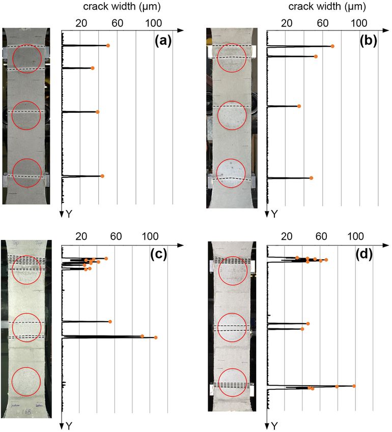
A. Hajiesmaeili and E. Denarié Cement and Concrete Research 143 (2021) 106368
Fig. 5. Capillary absorption measurement setup with chambers A, B and C
installed on the tensile specimen, and additional reference chamber for
compensation of effect of temperature variations.
were equipped with thermocouples in order to have a live measurement
Fig. 4. Test setup and instrumentation of the tensile specimen (dimensions
in mm). of the liquid temperature during the test.
For the capillary measurements, three chambers were clamped on
the constant cross-section of the specimens with the help of 4 threaded
transfer without lateral restraint of the specimen. The top and bottom
rods. A rubber gasket was placed between the specimen surface and the
indented steel shoes were tightly bolted to stiff steel plates, (d) on Fig. 3,
chamber’s support in order to ensure the water tightness. Each chamber
bolted directly on the machine’s heads without any hinge.
was then connected to a graduated glass pipette with a flexible plastic
The uniaxial tensile tests were conducted with a universal AMSLER
tube. A drop of oil was put over the water in the pipette to avoid
testing machine (capacity: 1000 kN). The test was controlled by the
evaporation and the liquid level in the pipettes corresponded to the level
mean value of two LVDT fixed on the specimen with a gauge length of
of the chambers to avoid hydrostatic pressure at the beginning of the
515 mm, as shown in Fig. 4, with a closed-loop deformation rate of
test. The subsequent changes of the liquid level were then recorded
0.003 mm/s. Two additional pairs of LVDT, set in two perpendicular
using a non-contact optical measurement system based on a digital
planes, were used to determine the elongation of the specimen and
camera and real-time image processing. As a reference, one chamber
check eccentricities under loading. The gauge lengths of the LVDT were
was clamped on an aluminum plate and was placed close to the spec
400 mm and 275 mm in XY and YZ planes, respectively.
imen in order to record the variation of the water level due to the effect
of ambient condition such as temperature variations and evaporation.
3.3. Crack measurement system This variation was then subtracted from the water level of the other
three chambers in order to have only the effect of capillary absorption.
A 3D Digital Image Correlation (DIC) system, was used in order to The installation of the capillary absorption setup is presented in Fig. 5.
measure the surface deformations. The system consisted of two 29 MP After the capillary absorption test under tension was completed, the
SVCam-hr29050 cameras with Zeiss Distagon35 lenses, connected to a damaged dumbbell specimens were unloaded, and cores were extracted
PC. The digital images were analyzed by the Vic-3D 8 software in order for the capillary absorption tests based on EN13057:2002 standard [45].
to determine the surface deformation. In order to make an identifiable Three cylinders were cut throughout the full depth (30 mm) of the
pattern, first the cast upper surface of the specimen was painted in white tensile specimen with water jet, at the exact locations which were in
and then black aerosol paint spray was used to create the speckle contact with the chambers during the capillary absorption measurement
pattern. The measurement area was 350 mm × 80 mm. The resolution of under tension, to be able to compare the results, Fig. 6 (a). Afterwards,
deformation measurement was 0.2 μm. the cylinders were oven dried until constant weight, at 50 ◦ C. In order to
ensure one-dimensional liquid transport, the side faces of the cylinders
3.4. Capillary absorption test were sealed with paraffin and thereafter, the specimen was kept in the
laboratory ambient conditions (20 ◦ C) for at least 12 h before being
An original setup was developed in order to measure capillary ab placed in the standard capillary absorption setup. Throughout the ab
sorption while the specimen was loaded. The setup consisted of 3 cy sorption tests, the immersion depth was kept constant at 2 mm. The
lindrical chambers with an internal diameter of 60 mm, which standard capillary absorption setup is schematically shown in Fig. 6 (b).
maintained the liquid in contact with the specimen surface. The cham The capillary absorption coefficient was calculated based on Eq. 1,
bers were made from Plexiglas that rested on an aluminum support. Two from the slope of the absorption versus square root of time in both
chambers (one for the specimen and the other one for the reference) cracked and uncracked states.
4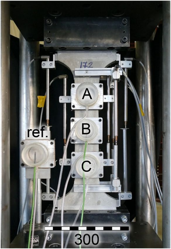
A. Hajiesmaeili and E. Denarié Cement and Concrete Research 143 (2021) 106368
Fig. 6. Dimensions and location of the cores extracted from the dumbbell specimen (a) and, a schematic sketch of standard capillary absorption setup (b) (di
mensions in mm).
and also the amount of unhydrated binders was significantly lower for
Table 3
the investigated PE-UHPFRC compared with conventional mixes,
Overview of the performed tests.
because of the replacement of 50% of the clinker by limestone filler. The
Specimen Loaded Capillary Capillary maximum degree of hydration for PE-UHPFRC was 52% and 60%, after
no. until absorption absorption
under tension after unloading
Waller [54] and Jensen [55] models, respectively.
1 Ultimate – – Tensile prop. &
strain crack char. 3.5. Overview of performed tests
2 Ultimate – –
strain
Table 3 gives an overview of all the performed tests. Three uniaxial
3 Ultimate – –
strain tensile tests until the end of hardening were performed in order to
4 0.015% 3× chambers – Serviceability characterize the tensile behavior of the material. Capillary absorption
5 0.03% 3× chambers – domain tests were carried out on the specimens for a wide range of tensile strain
6 0.05% 3× chambers 3× cylinders
levels. The investigated strain levels are 0.015%, 0.03%, 0.05%, 0.1%,
7 0.05% 3× chambers –
8 0.1% 3× chambers 3× cylinders 0.15%, 0.2%, 1% and 2%. First, the specimens were loaded to the
9 0.15% 3× chambers 3× cylinders defined strain levels, measuring the strain with the help of two LVDTs
10 0.2% 3× chambers 3× cylinders with the gauge length of 515 mm (Fig. 4). Meanwhile, the crack char
11 1% 3× chambers 3× cylinders Large acteristics were recorded by means of DIC. Afterward, the chambers
12 2% 3× chambers 3× cylinders deformation
were installed on the surface of the specimens and the capillary ab
sorption measurement started. Considering the effect of saturation
i = S.t0.5 (1) conditions on the capillary absorption, a separate specimen was tested
for each strain level. Repetition was done for the strain level of 0.05% to
where i is the cumulative absorption, t is time, and S is a constant characterize the variability of the obtained results.
referred as the sorptivity (capillary absorption coefficient).
It should be born in mind that original UHPFRC made with a ma 4. Results and discussion
jority of reactive powders have a very low degree of hydration, due to
their very low w/b ratio [52,53]. Thus, delayed hydration of the 4.1. Tensile response and evolution of damage under tension
unhydrated binders when the material is in contact with water during
permeability tests over several weeks may influence results, and require The uniaxial tensile test results of all the tested specimens are shown
the use of different liquids not reacting with cement [27]. However, this in Fig. 7. The x-axis shows the average tensile strain computed from the
effect was neglected in this study as the exposure time to water was short extensions of two pilot LVDT that controlled the deformation with the
gage length of 515 mm (setup shown in Fig. 4).
Fig. 7. Uniaxial tensile stress-strain response of the tested PE-UHPFRC specimens (a) zoom until 0.3% strain level (b).
5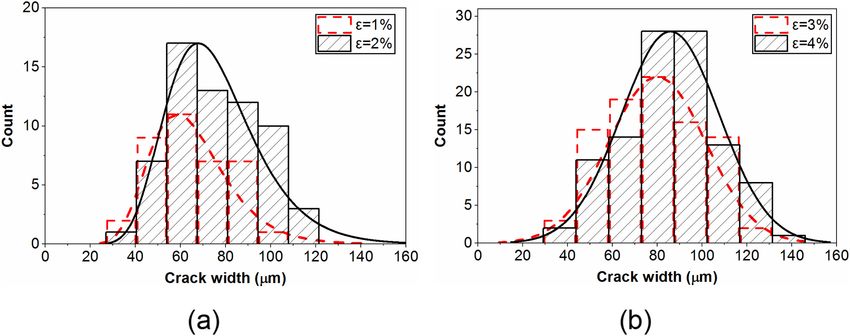
A. Hajiesmaeili and E. Denarié Cement and Concrete Research 143 (2021) 106368
Fig. 8. Unloading-loading cycles and apparent E modulus of a tensile specimen at different strain levels.
The evolution of damage under tension is an important property,
which can be characterized by determining the apparent E modulus at
different tensile strains by performing unloading-loading cycles. Fig. 8
shows the unloading-loading cycles and the apparent E modulus of a
tensile specimen at strain levels of 0.15, 0.4, 1, 2 and 3%.
4.2. Crack characteristics
The crack characteristics were analyzed up to the strain level of
4.5%. Considering the yield strain of approximately 0.2% for conven
tional steel reinforcement in structural members, 4.5% strain will never
be reached under service loads in RC structures. However, investigating
higher strains is still important to understand the full picture of the
evolution of the cracks and of the associated capillary absorption. Fig. 9
shows the crack numbers, and average, maximum, minimum and stan
Fig. 9. Crack number, and average, maximum, minimum and standard devia dard deviation of the crack width (wc) for a uniaxial tensile test. The
tion of the crack width under tension of specimen No. 2. specimen exhibited a multiple cracking behavior and the average crack
widths did not exceed 0.1 mm even up to a very high strain level of
The specimens had a strain-hardening behavior and numerous 4.5%.
multiple cracks developed gradually. As it is shown in Fig. 7, the elastic Fig. 10 shows the DIC images of the tensile specimen No. 2 at strain
limit (first crack strength) was above 7 MPa. The average elastic levels of 0.1, 0.2, 1, 2, 3 and 4% along with the crack analysis. The
modulus of the material in tension was 43 GPa, which was computed horizontal lines indicate the crack location and the dots show the cor
from the slope of the average straight line through the stress-strain data responding crack width. The gauge length of the strain εyy, which is
points of the specimen. Furthermore, it should be noted that compared represented by the colored contour plot, was 20 pixels, which was 1.43
to other results from the literature [33], the stress fluctuation in the mm in this study.
hardening zone was much lower. Fig. 7 highlights highly reproducible Fig. 11 represents the distribution of the crack width at the strain
tensile test results which confirm the robustness of the material and the levels of 1, 2, 3 and 4%. For the strain levels of 1 and 2%, a lognormal
effectiveness of the testing setup. distribution fits well on the results, as suggested in the literature for ECC
and SHCC materials [37,38,56]. However, for the higher strain levels of
6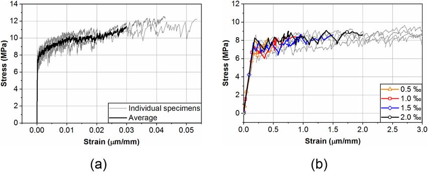
A. Hajiesmaeili and E. Denarié Cement and Concrete Research 143 (2021) 106368
Fig. 10. DIC images of the tensile specimen No.2 at different strain levels along with the crack analysis. (a) 0.1%, (b) 0.2%, (c) 1%, (d) 2%, (e) 3%, and (f) 4%.
3 and 4%, the distribution of the crack width was closer to a normal 4.3. Capillary absorption test under tension
distribution, Fig. 11 (b).
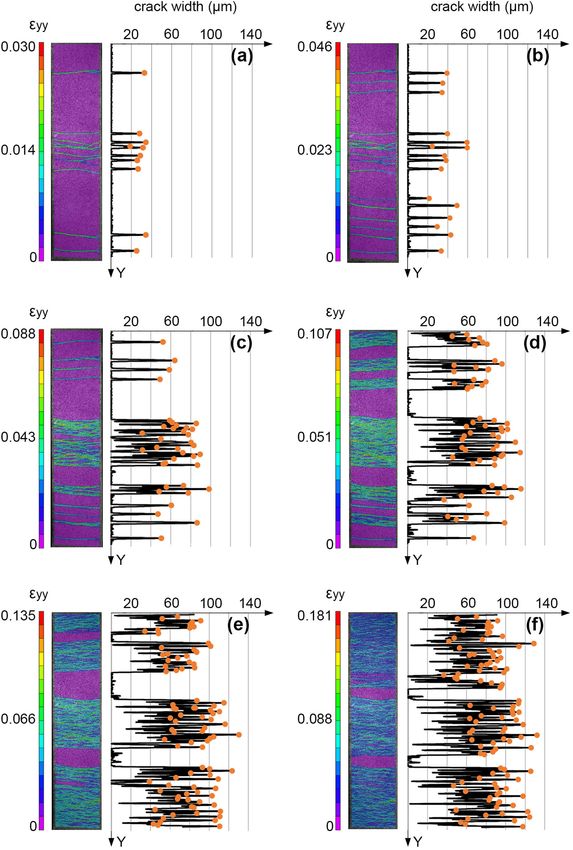
Fig. 12 illustrates the crack width after unloading for a strain level of Fig. 13 shows the average water capillary absorption under tension
4%. As it is shown, the maximum crack width after unloading decreased from the three chambers, for the strain level of 0.015 to 0.2%. Consid
significantly and reached below 0.05 mm. ering that the elastic limit of the material was around 0.02%, the strain
level of 0.015% was in the elastic domain and the specimen was still
uncracked. The capillary absorption coefficient for this strain level was
in the extremely low range of 3 to 4 g/m2√h that confirms the very
7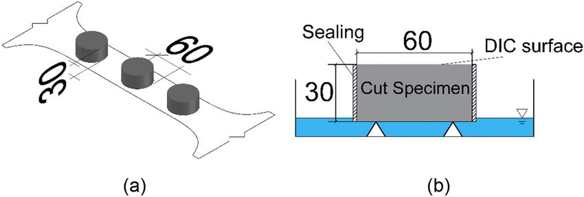
A. Hajiesmaeili and E. Denarié Cement and Concrete Research 143 (2021) 106368
Fig. 11. Crack width distribution: (a) for 1 and 2% strain levels - lognormal distribution, and (b) for 3 and 4% strain levels - normal distribution.
Fig. 13. Average water capillary absorption under tension, from three cham
bers for the strain levels of 0.015 to 0.2%.
μm and 33.6 μm along a length of 29.7 mm and 38.1 mm, respectively,
were present under the top chamber (A). One crack with a width of 38.8
μm along a length of 57.6 mm was present under the middle chamber
(B). Finally, one crack with a width of 44 μm along a length of 58.7 mm
was present under the bottom chamber (C). The average capillary ab
sorption coefficient at this strain level was 293 and 313 g/m2√h for the
first and the repeated specimen, respectively.
At the strain level of 0.1%, two cracks were present under chamber
A, while there was one crack each within the area of both the other
chambers. According to Table 4 and Fig. 14, the widest crack with a
width of 70.7 μm highly influenced the capillary absorption in the top
chamber while the other two chambers exhibited similar capillary ab
Fig. 12. Crack width after unloading for a strain level of 4%, (a) normal and sorption with a similar crack pattern.
(b) inverted. For the strain level of 0.15%, nine cracks with an average width of
34 μm located under chamber A, and three cracks with an average width
dense microstructure of the material. The strain level of 0.03% was just of 85 μm under chamber B, had a similar effect on capillary absorption.
after the elastic limit at which there was only one crack on the specimen. The capillary absorption of the bottom chamber (C), which did not
Accordingly, only the chamber that was on the cracked area was experience any crack in its area, remained close to 4 g/m2√h.
showing higher values and the capillary absorption from the two other At the strain level of 0.2%, more cracks developed on the top and
chambers remained close to 4 g/m2√h. bottom part of the specimen compared to the center. Six cracks were
Fig. 14 represents the crack patterns with respect to the location of found under chamber A. However, the cracks were situated close to the
the chambers as well as the crack widths for the strain levels of 0.05, 0.1, end of the chamber and therefore their lengths which were in direct
0.15 and 0.2%. In this figure, the positions of the cracks are outlined by contact with water, were shorter compared to that for the other two
dashed lines and the circles show the position of the chambers on the chambers. Two cracks with widths of 40.1 μm and 46.4 μm were present
specimens. At the strain level of 0.05%, two cracks with widths of 50.2 under chamber C. Four cracks with the width range of 50 to 100 μm were
8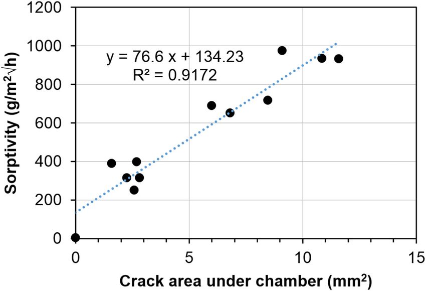
A. Hajiesmaeili and E. Denarié Cement and Concrete Research 143 (2021) 106368
Fig. 14. Crack positions and the corresponding crack width for the specimens loaded up to strain levels of (a) 0.05%, (b) 0.1%, (c) 0.15% and (d) 0.2%.
Table 4
Capillary absorption coefficients (g/m2√h) under tension, from each chamber and the average values for strain levels of 0.03 to 2%.
Strain level 0.03% 0.05% 0.05% 0.1% 0.15% 0.2% 1% 2%
Chamber A 4 315 348 976 935 651 1612 4341
Chamber B 502 314 300 390 932 689 1915 2682
Chamber C 4 250 291 397 4 717 1659 3724
Average 170 293 313 588 624 686 1729 3582
present in the middle of the bottom chamber and resulted in a higher level was 3582 g/m2√h. This is a very high value comparable with the
capillary absorption for this chamber. capillary absorption coefficient of red brick that is approximately 4000
Fig. 15 outlines the average water capillary absorption of the spec g/m2√h.
imen from three chambers against the square root of hour, for the strain The capillary absorption coefficient was calculated for each indi
levels of 1 and 2%, under tensile loading. At 1% strain level, the spec vidual chamber and is shown in Table 4 for the strain levels of 0.03 to
imen experienced 38 cracks along a length of 354.5 mm, which repre 2%. The variation of the capillary absorption from different chambers at
sents a crack density of 107 cracks per meter. The average of the crack the strain levels below 0.2% is the result of a limited number of cracks
width was 68.5 μm with a standard deviation of 17.4. The capillary and consequently non-uniform crack patterns at those strain levels. At
absorption coefficient of the specimen varied from 1600 to 1900 g/ the strain level of 0.03%, there was only one crack on the specimen
m2√h for the three chambers. under the chamber B. Similarly, as it is shown in Fig. 14, there was no
The crack density at the 2% strain level was 236 cracks per meter crack under the chamber C at the strain level of 0.15%.
with the average crack width of 68.2 μm and a standard deviation of In order to highlight the effect of cracks on capillary absorption,
18.7. With respect to the crack characteristics at 1% strain level, the Fig. 16 shows the capillary absorption as a function of crack area for the
number of cracks increased by a factor of two, while the average crack specimen tested at 0.05, 0.1, 0.15 and 0.2% strain level. In this figure,
width and standard deviation remained in a similar range. The average each point corresponds to one chamber and the crack area was calcu
capillary absorption coefficient for the three chambers at a 2% strain lated by the sum of the crack widths times crack lengths under the
9
A. Hajiesmaeili and E. Denarié Cement and Concrete Research 143 (2021) 106368
Fig. 17 versus the crack area calculated based on Fig. 9 and were
compared with the linear relationship calculated in Fig. 16. The results
fitted well on the linear relationship which confirmed both the validity
of the averaging method and the crack information provided in Fig. 9.
4.4. Capillary absorption test after unloading
Specimen for capillary absorption tests after unloading were cored
out of the dumbbell specimens for strain levels of 0.05%, 0.1%, 0.15%,
0.2%, 1% and 2%. Fig. 18 shows the average absorption of three cores,
which were taken from each specimen after unloading on the same lo
cations as that of the respective chambers A, B, C. The capillary ab
sorption increased gradually with increasing strain levels. Although
there was a linear correlation between capillary absorption and the
square root of time for the lower strain levels (0.05 and 0.1%), the
relation deviated from linearity at the higher strain levels. This can be
explained by the contrary effect of gravity on the capillary rise in the
Fig. 15. Average of water capillary absorption under tension, from three wider cracks which takes place for the configuration of the test after
chambers for the strain levels of 1 and 2%. EN13057:2002 [45] (soaking from bottom face).
Table 5 presents the capillary absorption coefficient of the specimens
that were tested after unloading (individual results and average), for the
investigated strain levels.
4.5. Discussion
Fig. 19 compares the capillary absorption of PE-UHPFRC with that of
SHCC under various strain levels, taken from Mechtcherine et al. [36]
and Wittmann et al. [43]. In this figure, the capillary absorption coef
ficient of PE-UHPFRC is the average of three values. In all the cases, the
specimen is damaged under tension and the capillary absorption test is
performed on the cores from the tensile specimen after unloading.
It can be noticed from Fig. 19 that the water capillary absorption of
PE-UHPFRC is at least one order of magnitude lower than that of SHCC.
This highlights the fact that although crack width limitation criteria are
a necessary condition for durability, the density of the microstructure
plays an equally important role on transport properties and thereupon
on the durability of the material. Moreover, as it can be seen in this
Fig. 16. Capillary absorption as a function of the crack area until the strain figure, even after experiencing the strain level of 2%, after unloading,
level of 0.2%. the absorption coefficient of PE-UHPFRC is lower than that of undam
aged normal concrete, which is in the range of 300 g/m2√h.
The influence of imposed tensile stresses on capillary absorption of
UHPFRC with steel fibers under tensile loading has been investigated by
Wittmann et al. [24]. Tensile test results for the same material are
presented in [57]. On this basis and considering a typical range of strain
levels corresponding to elastic limits of PE-UHPFRC from 0.015 to
0.02%, Fig. 20 shows a sudden increase in capillary absorption co
efficients after the elastic limit. A similar trend was observed for the PE-
UHPFRC.
Moreover, the capillary absorption coefficient of steel fiber UHPFRC
decreases by approximately 35% after unloading while according to
Fig. 21, the capillary absorption of PE-UHPFRC decreases at least 10
times after unloading. This can be explained by different crack closure
behaviors of these two materials after unloading. The stiffness of steel
fibers hinders the closure of cracks, while synthetic fiber can hardly
oppose to crack closure after unloading.
The durability related requirements for the Serviceability Limit State
(SLS) depend on both material properties and the expected service life of
the structure. Considering that the expected service life for UHPFRC
Fig. 17. Validation of the averaging method. applications is the full service life of the structure without any further
rehabilitation, the UHPFRC layer should remain impermeable during
chamber. The results showed a linear relation relationship between the the whole remaining service life of the structure after rehabilitation, to
capillary absorption and the crack area. fulfill the SLS criteria. The French standard on UHPFRC [58] followed
In order to validate the averaging method used for reporting the the normal and fiber-reinforced concrete codes [59] and recommended
capillary absorption at different strain levels, the average capillary ab limitations on the maximum crack width for the durability related SLS.
sorption at strain levels of 0.2, 1, and 2% from Table 4 were plotted in However, this approach is questionable according to the results of this
study and other investigations reported in the literature [24,60]. As
10A. Hajiesmaeili and E. Denarié Cement and Concrete Research 143 (2021) 106368
Fig. 18. Average of water capillary absorption test results from three cores, for the strain levels of (a) 0.05 to 0.2%, and (b) 1 and 2%, after unloading.
Table 5
Capillary absorption coefficients (g/m2√h) for tests after unloading, from each
core and the average values for strain level of 0.05 to 2%.
Strain level 0.05% 0.1% 0.15% 0.2% 1% 2%
Core A 25 46 87 57 203 142
Core B 24 18 53 48 186 211
Core C 25 22 5 77 75 224
Average 25 29 48 61 155 192
Fig. 20. Capillary absorption of UHPFRC with steel fibers and PE-UHPFRC
versus strain level.
Fig. 19. Comparison between capillary absorption coefficient of PE-UHPFRC,
and SHCC at different strain level after unloading.
such, in order to provide proper protective function throughout the
entire lifetime of the structure, the PE-UHPFRC layer should stay un-
cracked. Thus, the sum of the tensile stresses in a PE-UHPFRC layer
from internal and external action effects should remain below the tensile
elastic limit of the material at SLS, from a purely local, deterministic
point of view. However, further investigations should be carried out to
generalize these findings to the determination of Serviceability Limit
States for Strain Hardening UHPFRC in structural members considering
the deterioration mechanisms followed by the ingress of liquids through Fig. 21. Average capillary absorption coefficient of the PE-UHPFRC versus
microcracks in UHPFRC, with or without rebar. strain level.
5. Conclusions PE-UHPFRC was investigated in two ways: (I) under tension, using an
original testing setup, and (II) after unloading, based on standards. Ac
The effect of the strain level on the capillary absorption of water in cording to the results,
11A. Hajiesmaeili and E. Denarié Cement and Concrete Research 143 (2021) 106368
• The cracking behavior of PE-UHPFRC was similar to that of other [5] C. Hall, Water movement in porous building materials—I. Unsaturated flow theory
and its applications, Building and Environment. 12 (1977) 117–125. doi:
cementitious materials with high deformation capacity (ECC and
https://doi.org/10.1016/0360-1323(77)90040-3.
SHCC), up to a strain level of 2%, and the cracks width similarly [6] R. Lucas, Rate of capillary ascension of liquids, Kolloid Z. 23 (1918) 15–22.
followed a lognormal distribution. The average crack width [7] E.W. Washburn, The dynamics of capillary flow, Phys. Rev. 17 (1921) 273.
remained below 0.1 mm throughout the tensile behavior. However, [8] J. Bao, L. Wang, Capillary imbibition of water in discrete planar cracks, Constr.
Build. Mater. 146 (2017) 381–392, https://doi.org/10.1016/j.
for higher strain levels (3 and 4%), the crack width distribution conbuildmat.2017.04.129.
changed towards a normal distribution. [9] D. Gardner, A. Jefferson, A. Hoffman, Investigation of capillary flow in discrete
• The capillary absorption of PE-UHPFRC after unloading was at least cracks in cementitious materials, Cem. Concr. Res. 42 (2012) 972–981, https://doi.
org/10.1016/j.cemconres.2012.03.017.
ten times less than that of SHCC, which is a comparable cementitious [10] D. Gardner, A. Jefferson, A. Hoffman, R. Lark, Simulation of the capillary flow of
materials in terms of deformation capacity, at all the studied strain an autonomic healing agent in discrete cracks in cementitious materials, Cem.
levels. Concr. Res. 58 (2014) 35–44, https://doi.org/10.1016/j.cemconres.2014.01.005.
[11] Y.A.V. Zaccardi, N.M. Alderete, N. De Belie, Improved model for capillary
• There was a sudden significant increase in capillary absorption of absorption in cementitious materials: Progress over the fourth root of time, Cem.
UHPFRC (including literature) after the elastic limit under tensile Concr. Res. 100 (2017) 153–165.
loading. [12] H. Huang, X. Gao, H. Wang, H. Ye, Influence of rice husk ash on strength and
permeability of ultra-high performance concrete, Constr. Build. Mater. 149 (2017)
• The capillary absorption of damaged PE-UHPFRC after unloading 621–628, https://doi.org/10.1016/j.conbuildmat.2017.05.155.
increased gradually with the strain level, and remained below 60.9 [13] S. Pyo, H.K. Kim, Fresh and hardened properties of ultra-high performance
g/m2√h even after experiencing a strain level of 0.2% before concrete incorporating coal bottom ash and slag powder, Constr. Build. Mater. 131
(2017) 459–466, https://doi.org/10.1016/j.conbuildmat.2016.10.109.
unloading.
[14] D. Dobias, R. Pernicova, T. Mandlik, Water Transport properties and depth of
• There was a considerable difference of approximately one order of chloride penetration in ultra high performance concrete, in: Key Engineering
magnitude in the rate of liquid ingress, when comparing the capillary Materials, Trans Tech Publ, 2016: pp. 137–142.
absorption of same PE-UHPFRC samples, under tension and after [15] W. Wang, J. Liu, F. Agostini, C.A. Davy, F. Skoczylas, D. Corvez, Durability of an
ultra high performance fiber reinforced concrete (UHPFRC) under progressive
unloading. This highlights the necessity of developing more realistic aging, Cem. Concr. Res. 55 (2014) 1–13, https://doi.org/10.1016/j.
test methods in order to define the durability properties and cemconres.2013.09.008.
serviceability limit state of cementitious materials with high defor [16] C.M. Tam, V.W.Y. Tam, K.M. Ng, Assessing drying shrinkage and water
permeability of reactive powder concrete produced in Hong Kong, Constr. Build.
mation capacity. Mater. 26 (2012) 79–89, https://doi.org/10.1016/j.conbuildmat.2011.05.006.
• Although crack width limitation is a necessary condition for dura [17] D. Mestrovic, D. Cizmar, V. Stanilovic, Reactive powder concrete: material for the
bility, the density of the microstructure of the material plays an 21st century, WIT Trans. Eng. Sci. 57 (2007) 127–133, https://doi.org/10.2495/
MC070131.
equally important role on transport properties and thereupon on its [18] N. Roux, C. Andrade, A. Sanjuan M, Experimental study of durability of reactive
durability and protective properties. powder concretes, Journal of Materials in Civil Engineering. 8 (1996) 1–6. doi:
• Fixing threshold values of crack width for durability must be done https://doi.org/10.1061/(ASCE)0899-1561(1996)8:1(1).
[19] F. Toutlemonde, P. Roenelle, Z. Hajar, A. Simon, R. Lapeyrère, R.-P. Martin, S.
considering the relevant transport mechanisms. Ramanich, L. Baron, Long-term material performance checked on world’s oldest
UHPFRC road bridges at Bourg-Lès-Valence, in: RILEM-Fib-AFGC International
CRediT authorship contribution statement Symposium on UHPFRC, 2013: pp. 265–274.
[20] F. Toutlemonde, V. Bouteiller, G. Platret, M. Carcasses, M. Lion, F. Toutlemonde,
Field demonstration of UHPFRC durbility, Concr. Int. 32 (2010) 39–45.
A. Hajiesmaeili1, E. Denarié2. [21] A. Sajna, E. Denarié, V. Bras, Assessment of UHPFRC based bridge rehabilitation in
1 – corresponding author, conducted all the experiments presented Slovenia, two years after application, in: M. Schmidt, E. Fehling, C. Glotzbach,
S. Fröhlich, S. Piotrowski (Eds.), Proceedings HIPERMAT 2012, 3rd International
in the paper along with the writing of the full article.
Symposium on Ultra-High Performance Concrete, Uni Kassel, Kassel, Germany,
2 – thesis supervisor. 2012, pp. 937–944.
[22] K. Kono, H. Musha, T. Kawaguchi, A. Eriguchi, S. Tanaka, T. Kobayashi, M. Ikeda,
Durability study of the first PC bridge constructed with ultra high strength fiber
Declaration of competing interest
reinforced concrete in Japan, in: Proceedings of the RILEM-Fib-AFGC International
Symposium on Ultra-High Performance Fibre-Reinforced Concrete, 2013: pp.
The authors declare no conflict of interest. 239–248.
[23] M. Thomas, B. Green, E. O’Neal, V. Perry, S. Hayman, A. Hossack, Marine
performance of UHPC at Treat Island, in: Proceedings of the 3rd International
Acknowledgments Symposium on UHPC and Nanotechnology for High Performance Construction
Materials, Kassel, Germany, Uni Kassel, Kassel, Germany, 2012, pp. 365–370.
This project is financially supported by the Swiss National Science [24] F.H. Wittmann, X. Yao, P. Wang, P. Zhang, T. Zhao, Influence of an imposed tensile
stress and subsequent self-healing on capillary absorption and chloride penetration
Foundation (grant 407040_154063/1) through the National Research into HPFRCC, in: Seventh International RILEM Workshop on High Performance
Program “Energy Turnaround” (NRP 70). The authors would like to Fiber Reinforced Cement Composites (HPFRCC7), Germany, Stuttgart, 2015,
gratefully acknowledge Dyneema, Omya, LafargeHolcim, and Sika for pp. 251–258.
[25] R. Wang, X. Gao, Q. Li, Y. Yang, Influence of splitting load on transport properties
donating the PE fiber, limestone filler, cement, and superplasticizer of ultra-high performance concrete, Constr. Build. Mater. 171 (2018) 708–718,
respectively. The authors also would like to acknowledge Serge Despont https://doi.org/10.1016/j.conbuildmat.2018.03.174.
and Gilles Guignet, technicians at GIS/EPFL, for their help regarding the [26] P. Wang, X. Yao, F.H. Wittmann, P. Zhang, T. Zhao, Influence of imposed
compressive stress and subsequent self-healing on capillary absorption and
preparation of test setups, DIC measurements, and performing the tests. chloride penetration into UHPFRCC, in: Seventh International RILEM Workshop on
High Performance Fiber Reinforced Cement Composites (HPFRCC7), Germany,
References Stuttgart, 2015, pp. 243–250.
[27] J.-P. Charron, E. Denarié, E. Brühwiler, Transport properties of water and glycol in
an ultra high performance fiber reinforced concrete (UHPFRC) under high tensile
[1] E. Denarié, M. Kazemi Kamyab, E. Brühwiler, B.G. Haddad, S. Nendaz, Béton fibré
deformation, Cem. Concr. Res. 38 (2008) 689–698, https://doi.org/10.1016/j.
ultra performant pour la maintenance, un nouvel élan, Tracés N◦ 12. (2011) 20–23.
cemconres.2007.12.006.
[2] E. Brühwiler, E. Denarié, Rehabilitation and strengthening of concrete structures
[28] Z. Ma, T. Zhao, X. Yao, Influence of applied loads on the permeability behavior of
using ultra-high performance fibre reinforced concrete, Structural Engineering
ultra high performance concrete with steel fibers, J. Adv. Concr. Technol. 14
International: Journal of the International Association for Bridge and Structural
(2016) 770–781, https://doi.org/10.3151/jact.14.770.
Engineering (IABSE). 23 (2013) 450–457, https://doi.org/10.2749/
[29] Y. Li, K.H. Tan, E.-H. Yang, Influence of aggregate size and inclusion of
101686613X13627347100437.
polypropylene and steel fibers on the hot permeability of ultra-high performance
[3] E. Denarié, E. Brühwiler, Cast-on site UHPFRC for improvement of existing
concrete (UHPC) at elevated temperature, Constr. Build. Mater. 169 (2018)
structures–achievements over the last 10 years in practice and research, 7th
629–637, https://doi.org/10.1016/j.conbuildmat.2018.01.105.
Workshop on High Performance Fiber Reinforced Cement Composites, 1–3, June
[30] J.-P. Charron, E. Denarié, E. Brühwiler, Permeability of ultra high performance
2015, Germany, Stuttgart, 2015.
fiber reinforced concretes (UHPFRC) under high stresses, Mater. Struct. 40 (2007)
[4] A. Hajiesmaeili, E. Denarie, Next Generation UHPFRC for Sustainable Structural
269–277, https://doi.org/10.1617/s11527-006-9105-0.
Applications, ACI Special Publication. 326 (2018).
12A. Hajiesmaeili and E. Denarié Cement and Concrete Research 143 (2021) 106368
[31] V.C. Li, On engineered cementitious composites (ECC), J. Adv. Concr. Technol. 1 Nuclear Instruments and Methods in Physics Research Section A: Accelerators,
(2003) 215–230. Spectrometers, Detectors and Associated Equipment. 620 (2010) 414–420.
[32] I. Curosu, M. Liebscher, V. Mechtcherine, C. Bellmann, S. Michel, Tensile behavior [45] BS EN 13057:2002, Determination of Resistance of Capillary Absorption, British
of high-strength strain-hardening cement-based composites (HS-SHCC) made with Standards Institution, 2002.
high-performance polyethylene, aramid and PBO fibers, Cem. Concr. Res. 98 [46] S. Fennis, J.C. Walraven, J.A. Den Uijl, Compaction-interaction packing model:
(2017) 71–81. regarding the effect of fillers in concrete mixture design, Mater. Struct. 46 (2013)
[33] R. Ranade, V.C. Li, M.D. Stults, W.F. Heard, T.S. Rushing, Composite properties of 463–478.
high-strength, high-ductility concrete., ACI Materials Journal. 110 (2013). [47] ASTM C1437-15, Standard Test Method for Flow of Hydraulic Cement Mortar,
[34] P.G. Wang, F.H. Wittmann, P. Zhang, E.H. Lehmann, T.J. Zhao, Observation of ASTM International, 2015.
water penetration into cracked and water repellent SHCC after imposed strain by [48] H. Neuber, Der zugbeanspruchte Flachstab mit optimalem Querschnittsübergang,
means of neutron radiography, Restoration of Buildings and Monuments. 20 Forschung Im Ingenieurwesen A. 35 (1969) 29–30, https://doi.org/10.1007/
(2014) 95–102. BF02559032.
[35] P. Zhang, F.H. Wittmann, B. Villmann, T.J. Zhao, V. Slowik, Moisture diffusion in [49] E. Denarié, M. Maître, D. Conciatori, E. Brühwiler, Air permeability measurements
and capillary suction of integral water repellent cement based materials, in: for the assessment of the in situ permeability of cover concrete, in: International
Proceedings of 5th International Conference on Water Repellent Treatment of Conference on Concrete Repair, Rehabilitation and Retrofitting, Cape Town, South
Building Materials, Aedificatio Publishers, Brussels, Belgium, 2008, pp. 273–286. Africa, 2005, pp. 475–481.
[36] V. Mechtcherine, M. Lieboldt, Effect of cracking on air-permeability and water [50] A. Helbling, E. Brühwiler, Eine neue Halterung für Zugversuche mit Beton-
absorption of strain hardening cement-based composites, in: Proceedings, Fifth Probekörper, Material Und Technik. 15 (1987) 103–107.
International RILEM Workshop on High Performance Fiber Reinforced Cement [51] E. Denarie, E. Brühwiler, Structural rehabilitations with ultra-high performance
Composites (HPFRCC 5), 2007: pp. 305–312. fibre reinforced concretes (UHPFRC)/Strukturelle Instandsetzung von
[37] W.P. Boshoff, C.J. Adendorff, Modelling SHCC cracking for durability, Fracture and Betonbrücken mit Ultra-hochleistungsfähigem Faserfeinkornbeton (UHFB),
Damage of Advanced Fibre-Reinforced Cement-Based Materials, Aedificatio Restoration of Buildings and Monuments. 12 (2006) 93–108.
Publishers, Dresden, 2010. [52] A. Kamen, E. Denarie, E. Brühwiler, Thermal effects on physico-mechanical
[38] W.P. Boshoff, F. Altmann, C.J. Adendorff, V. Mechtcherine, A new approach for properties of ultra-high-performance fiber-reinforced concrete, ACI Mater. J. 104
modelling the ingress of deleterious materials in cracked strain hardening cement- (2007) 415.
based composites, Mater. Struct. 49 (2016) 2285–2295. [53] A. Loukili, A. Khelidj, P. Richard, Hydration kinetics, change of relative humidity,
[39] M. Şahmaran, V.C. Li, Influence of microcracking on water absorption and and autogenous shrinkage of ultra-high-strength concrete, Cem. Concr. Res. 29
sorptivity of ECC, Mater. Struct. 42 (2009) 593–603. (1999) 577–584.
[40] M. Lepech, V.C. Li, Water permeability of cracked cementitious composites, [54] V. Waller, Relations entre composition des bétons, exothermie en cours de prise et
Proceedings ICF11, 11th International Conference on Fracture, 2002. résistance en compression, in, Doctoral Thesis, Thèse de doctorat de L’école
[41] M.D. Lepech, V.C. Li, Water permeability of engineered cementitious composites, Nationale des Ponts et Chaussées, LCPC, 1999.
Cem. Concr. Compos. 31 (2009) 744–753. [55] O.M. Jensen, P.F. Hansen, Water-entrained cement-based materials: I. Principles
[42] F.H. Wittmann, P. Wang, P. Zhang, T. Zhao, F. Beltzung, Capillary absorption and and theoretical background, Cement and Concrete Research. 31 (2001) 647–654.
chloride penetration into neat and water repellent SHCC under imposed strain, in: [56] C.J. Adendorff, W.P. Boshoff, G. Van Zijl, Characterisation of crack distribution of
2nd International RILEM Conference on Strain Hardening Cementitious strain-hardening cement composites (SHCC) under imposed strain, in: Advances in
Composites (SHCC2-Rio), RILEM Publications SARL Rio de Janeiro, 2011: pp. Cement-based Materials, 2010.
165–172. [57] P. Zhang, W. Ma, F. Wittmann, W. Wang, T. Zhao, Influence of steel fiber content
[43] F.H. Wittmann, T. Zhao, L. Tian, F. Wang, L. Wang, Aspects of durability of strain on fracture energy of HPFRCC, in: High Performance Fiber Reinforced Cement
hardening cement-based composites under imposed strain, in: G. Van Zijl, W.P. Composites (HPFRCC7), Germany, Stuttgart, 2015, pp. 119–125.
Boshoff (Eds.), Advances in Cement-based Materials, Taylor & Francis Group, [58] NF P18-710: National Addition to Eurocode 2–Design of Concrete Structures:
2010: pp. 173–179. Specific Rules for Ultra-high Performance Fiber-reinforced Concrete (UHPFRC),
[44] P. Zhang, F.H. Wittmann, T.J. Zhao, E.H. Lehmann, L. Tian, P. Vontobel, AFNOR. (2016).
Observation and quantification of water penetration into strain hardening cement- [59] Fib Model Code for Concrete Structures 2010, Berlin, Germany, 2013.
based composites (SHCC) with multiple cracks by means of neutron radiography, [60] A. Rafiee, Computer Modeling and Investigation on the Steel Corrosion in Cracked
Ultra High Performance Concrete, Doctoral Thesis. 21 (2012).
13You can also read