On the reflection of time-domain acoustic spherical waves by a sinusoidal diffraction grating
←
→
Page content transcription
If your browser does not render page correctly, please read the page content below
Acta Acustica 2021, 5, 6
Ó G. Gao et al., Published by EDP Sciences, 2021
https://doi.org/10.1051/aacus/2020033
Available online at:
https://acta-acustica.edpsciences.org
LETTER TO THE EDITOR
On the reflection of time-domain acoustic spherical waves
by a sinusoidal diffraction grating
Guochao Gao1, Paul Cristini2,*, Nathalie Favretto-Cristini2, and Carole Deumié1
1
Aix-Marseille Univ, CNRS, Centrale Marseille, Institut Fresnel, 13397 Marseille, France
2
Aix-Marseille Univ, CNRS, Centrale Marseille, LMA, 13453 Marseille, France
Received 25 August 2020, Accepted 17 December 2020
Abstract – This work reports on some results obtained from numerical simulations of time-domain acoustic
wave propagation in the presence of a periodically rough interface. Emphasis is put on the structure of the
reflected signals in the presence of a sinusoidal grating. More specifically, we investigate the effect of the
frequency bandwidth of the emitted signal and the effect of the incident wavefront sphericity on the signals
reflected from the rough interface and associated with the different diffraction orders.
Keywords: Wave scattering, Periodic rough surface, Grating equation, Numerical simulation, Time domain
1 Introduction wave/interface interaction. Moreover, despite elastic effects
(e.g. mode conversions, surface waves) play an important
The main objective that underlies the work presented role in the real geophysical world, we consider here a very
here is to better understand the impact of rough interfaces simplified case, namely acoustic waves interacting with
in seismic wave propagation and in seismic imaging, in order sinusoidal interfaces, in order to better understand the effect
to possibly better handle rough interfaces. This is an impor- of roughness characteristics on the spherical wavefronts in
tant topic, as the presence of interfaces with irregularities the time domain.
leads to complex wave propagation phenomena, such as Wave reflection from rough interfaces has been widely
combination of reflections, scattering and other effects, addressed in literature either in optics, acoustics, or seismics
resulting in difficulties in the reconstruction of the shape (e.g. [6–10]). In particular, the diffraction of harmonic plane
of the interfaces (useful for both geologists and geophysi- waves by a periodic grating has been deeply investigated,
cists) and in the estimation of seismic parameters (velocity, and therefore is now very well known [11, 12]. Indeed, when
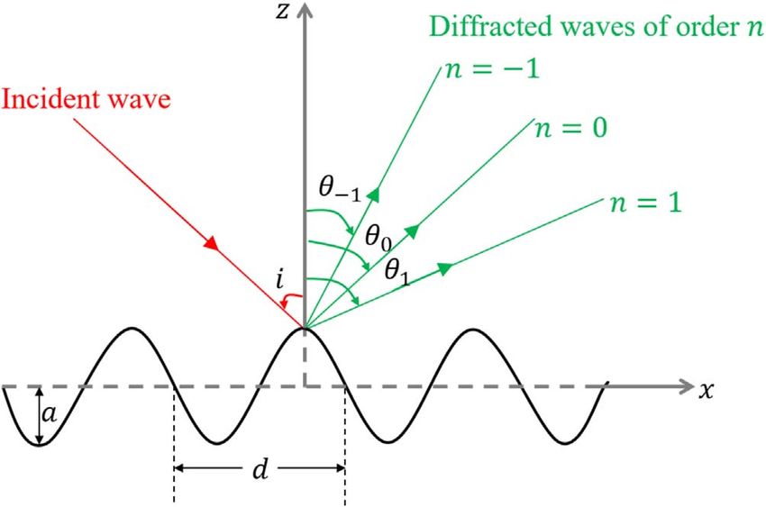
density, etc). As an example, the rugged topography of the a monochromatic acoustic wave (with wavelength k) strikes
basaltic surfaces generates severe wave distortion and under the incidence angle i a periodic interface (with a
scattering of seismic energy, and hence has a detrimental spatial period d), it gives rise to several diffracted
effect on seismic imaging quality of underlying geological monochromatic waves of order n that propagate along the
structures [1, 2]. This detrimental effect is even greater than directions hn (Fig. 1), defined by the well-known grating
that provided by internal heterogeneities of basalt layers [3]. equation [11–14]:
As a result, imaging of sub-basalt areas is still a major k
concern in volcano seismology or in hydrocarbon exploration sin hn ¼ sin i þ n n ¼ 0; 1; 2; . . .
d
[4, 5]. Improvements in this field can then have an impact at
different scales, from meters in environmental contexts to In this work, we consider a sinusoidal grating. It is worth
kilometers at the exploration scale, and tens of kilometers noting that this equation is valid for any type of periodic
in a regional scale. Most natural geological topographies, like gratings ([14], Appendix D). Considering another type of
basalt interfaces, have roughness on scales from centimeters grating only changes the diffraction efficiency and thus
to kilometers, and the roughness pattern appears to be frac- the amplitude of the different diffraction orders.
tal (i.e. identical at different scales) (Martini & Bean [3]). In the case of an incident non-monochromatic acoustic
Nevertheless, in the work presented here, we focus only on wave, that carries naturally several wavelengths, the angle
periodically rough interfaces, since this kind of interfaces hn associated with a given diffraction order n is no more
can more easily provide useful physical insights into the unique but lies within a broad range provided by the
grating equation. This phenomenon is called angular
*Corresponding author: cristini@lma.cnrs-mrs.fr dispersion. Accordingly, there is also a temporal dispersion
This is an Open Access article distributed under the terms of the Creative Commons Attribution License (https://creativecommons.org/licenses/by/4.0),
which permits unrestricted use, distribution, and reproduction in any medium, provided the original work is properly cited.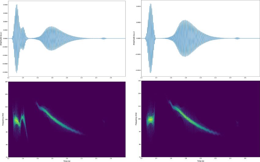
2 G. Gao et al.: Acta Acustica 2021, 5, 6
of the signals associated with the different orders, and the
dispersion follows different laws according to the diffraction
order. It has to be pointed out here that, as shown by the
grating equation, only the higher-order (|n| 1) diffracted
waves, and not the specular reflection (i.e. the zeroth-order
diffraction), are affected by dispersion.
Replacing plane waves by spherical waves makes the
issue of the wave/rough interface interaction much more
complex. Indeed, all the plane waves that compose the
spherical wave strike the interface under different incidence
angles, modifying the condition of existence of a given
diffraction order. Very few works have been concerned with
the interaction of harmonic acoustic spherical waves with a
rough interface (e.g. [15]), and to the best of our knownledge,
study of the interaction between a non-monochromatic
spherical acoustic wave with a periodic rough interface is Figure 1. Schematic representation of the reflection of a
still lacking. The main goal of this work is then to analyze harmonic plane wave from a periodic rough interface.
the reflection of a non-harmonic spherical wave, propagating
in a homogeneous acoustic medium, from a sinusoidal
grating. We focus more particularly on the effect of the inci- f0 is k0 = 15 m. The bottom is a sine-shaped periodic rough
dent wavefront sphericity on the diffracted waves. The pffiffiffi amplitude and period are a = k0/2 = 7.5 m
surface whose
analysis relies on 2D numerical simulations conducted in and d ¼ 2k0 21:2 m respectively. The bottom of the
the time domain. computational model is modelled as a perfectly reflecting
surface. The other boundaries are absorbing using perfectly
matched layers [17]. In this configuration, the maximum
2 Configurations and numerical modelling possible value for the incidence angle is 45°.
For the time marching, we use a Newmark scheme
The numerical simulations are performed with the which is second-order accurate. The different parameters
open-source package SPECFEM2D1 current source [16], of the numerical simulations are carefully selected so that
published under the CeCILL v2 license, that solves the wave we obtain stable and accurate results. As shown in the
equation without any approximation using a spectral- snapshots presented hereafter, no spurious reflections are
element method. The Spectral-Element Method (SEM) is observed from the sides of the domain where a perfectly
based upon a high-order piecewise polynomial approxima- matched layer is implemented.
tion of the weak formulation of the wave equation. It combi- Because of the complexity of the wavefield generated in
nes the accuracy of the pseudospectral method with the this type of configuration, we consider two rough interfaces,
flexibility of the finite-element method. In this method, the namely a half-flat half-rough interface and a fully rough
wavefield is represented in terms of high-degree Lagrange interface, to allow the diffraction orders generated by
interpolants, and integrals are computed based upon positive incident angles and orders generated by negative
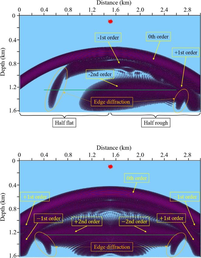
Gauss-Lobatto-Legendre quadrature. This combination incident angles to be separated. Snapshots of the wavefields
leads to perfectly diagonal mass matrix, which in turn leads after reflection of the incident wavefiled from the rough
to a fully explicit time scheme that lends itself very well to interfaces are illustrated in Figure 2. It is clearly seen that
numerical simulations on parallel computers. Complex orders of diffraction greater than two do not propagate in
models that include fluid, elastic, viscoelastic, anisotropic these two configurations. For the half-flat half-rough
or porous media can be modelled, making the SEM a interface configuration (Fig. 2a), the 2nd-order diffraction
method of choice for the numerical modelling of wave is well separated from the ±1st-order diffractions. The
progagation in complex media. Furthermore, the SEM ±1st-order diffractions interfere only in the right part of
allows for the accurate handling of curved interfaces making the computational domain. For the fully rough configura-
this numerical method very well adapted to the solution of tion (Fig. 2b), besides the aforementioned diffraction
the problem of the reflection of a spherical wave from a cor- orders, a +2nd-order diffraction is present. The ±2nd-order
rugated surface. diffractions only interfere in an area around the vertical to
We consider a computational domain with horizontal the source while the ±1st-order diffractions interfere almost
and vertical sizes of 3000 m and 1605 m. The domain is everywhere. For the two configurations, spurious diffrac-
homogeneous and composed of a medium with a wave veloc- tions generated by the edges of the rough part of the
ity of 1500 m/s. We consider a point source located at interfaces are seen (Fig. 2).
x = 1500 m, y = 105 m that emits a tone burst signal with The distribution of the diffracted orders, calculated from
a central frequency f0 of 100 Hz and a bandwidth of 30 Hz. the grating equation, as a function of the incident angle and
As a consequence, the wavelength at the central frequency the frequency content of the emitted signal is illustrated in
Figure 3. For a given diffraction order, the bounds of the
1
https://github.com/geodynamics/specfem2d domain of existence are given by the curves associated with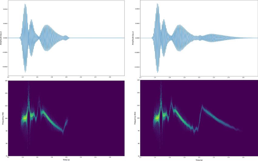
G. Gao et al.: Acta Acustica 2021, 5, 6                                             3

                                                                     3 Time-frequency analysis of the numerical
                                                                       results
                                                                         In order to identify the modification of the temporal
                                                                     characteristics of the emitted signal after reflection from
                                                                     the rough interfaces, we perform a time-frequency analysis
                                                                     using a reassigned spectrogram [18]. The use of a reassigned
                                                                     time-frequency representation allows for a more accurate
                                                                     analysis by exhibiting the fine structures of the received
                                                                     signals. Figures 4–6, present the temporal signal, together
                                                                     with its reassigned spectrogram, recorded at three distinct
                                                                     positions along the horizontal array that is located at a
                                                                     distance of 270 m from the rough interfaces. For the sake
                                                                     of comparison, the results for the case of a half-flat half-
                                                                     rough interface and for a fully rough interface are shown
                                                                     in Figures 4–6. The first receiver is situated at x = 400 m
                                                                     (left of the source). Note that this receiver is above the flat
                                                                     part of the half-flat half-rough interface. The second recei-
                                                                     ver is situated at x = 2300 m (right of the source) and is
                                                                     above the rough part of the half-flat half-rough interface.
                                                                     The third receiver is situated at the middle of the receiver
                                                                     array at x = 1500 m, so exactly vertical to the source.
                                                                         The signals received at the first receiver (also noted
                                                                     trace 1) for both the half-flat half-rough and full rough
                                                                     interfaces are shown in Figure 4.
                                                                         According to Figure 2a, the signal obtained for the case
                                                                     of the half-flat half-rough interface exhibits a first wave
                                                                     packet corresponding to the specular reflection (i.e. the
                                                                     zeroth-order diffraction), and a second wave packet corre-
Figure 2. Snapshots (at time (a) t = 1.74 s, (b) t = 1.8 s) of the   sponding to diffraction of order 2 (Fig. 4a). In between
wavefields after reflection of the incident wavefield from (a) a        these two wave packets and after the second wave packet,
half-flat half-rough interface, (b) a fully rough interface. The      two small wave packets can be observed corresponding to
source location is indicated by a red star, while the horizontal
                                                                     the diffraction by the edges of the rough interface of finite
array of receivers is indicated by a green line.
                                                                     length. It can be clearly seen that the specular reflection
                                                                     is not affected by the rough interface and that the wave
                                                                     packet associated to the 2nd diffraction order is strongly
                                                                     dispersed as expected from the analysis of the grating
                                                                     equation. For the case of the fully rough interface, in addi-
                                                                     tion to the wave packet associated to the 2nd diffraction
                                                                     order, two wave packets associated to the +1st and 1st
                                                                     diffraction order are present as well (Fig. 4). These latter
                                                                     packets are much less dispersed than the former one, which
                                                                     is consistent with the results shown in Figure 3.
                                                                         The signals received at the second receiver, together
                                                                     with its associated reassigned spectrograms, are represented
                                                                     for the two types of interfaces in Figure 5. The 0th-, 1st-
                                                                     and 2nd-order diffractions can be clearly seen for the half-
                                                                     flat half-rough configuration (Fig. 5). For the fully rough
Figure 3. Domains of existence (bounded by full lines) for the       configuration, in addition to these wave packets, a strongly
different diffracted orders (0, ±1, ±2) as a function of the         dispersed wave packet associated with the +2nd-order
incident angle and frequency content of the emitted signal.          diffraction occurs at the end of the signal (Fig. 4). In
                                                                     between, the +2nd-order wave diffracted packet and the
                                                                     2nd-order wave diffracted packet, a wave packet of small
the solution of the grating equation for the minimum                 amplitude and corresponding to the diffraction by the edge
wavelength (i.e. maximum frequency of the signal) and for            of the model can be observed.
the maximum wavelength (i.e. minimum frequency of the                    The signal received at the third receiver (situated
signal). From Figure 3, it can be seen that the greater the          exactly vertical to the source), together with its associated
diffraction order, the wider the domain of its existence,            reassigned spectrogram, is shown in Figure 6 for the
leading to a diffracted signal strongly dispersed.                   two types of interfaces. The 0th, 1st and 2nd-order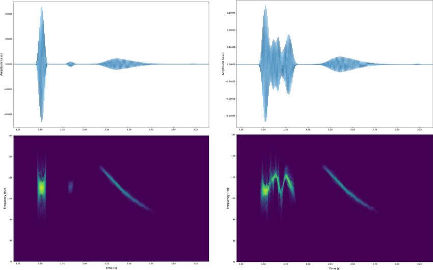
4                                          G. Gao et al.: Acta Acustica 2021, 5, 6

Figure 4. (Top) Signal (trace 1) received at the first receiver (x = 400 m) and (bottom) associated reassigned spectrogram, for the
case of a half-flat half-rough interface (left) and for a fully rough interface (right).

Figure 5. (Top) Signal (trace 475) received at the 475th receiver (x = 2300 m) and (bottom) associated reassigned spectrogram, for
the case of a half-flat half-rough interface (left) and for a fully rough interface (right).
G. Gao et al.: Acta Acustica 2021, 5, 6                                                    5

Figure 6. (Top) Signal (trace 276) received at the 276th receiver (x = 1500 m) and (bottom) associated reassigned spectrogram, for
the case of a half-flat half-rough interface (left) and for a fully rough interface (right). The receiver is exactly vertical to the source.

diffractions can be observed for the half-flat half-rough               dispersed the associated temporal signals. Moreover, we
configuration (Fig. 5). However, the 0th and the 1st-order             also showed that the different signals associated to different
diffractions are not well separated. Surprisingly, for the             diffraction orders can interfere and in the special case where
fully rough configuration, the ±1st-order diffractions are              the receiver is exactly vertical to the source the ±1st-order
missing and the wave packet associated to the 2nd-order               diffractions interfere in a destructive way and therefore
diffraction is much pronounced. This is mostly due to the              cancel each other. These interferences are specific to a
symmetry of this configuration that emphasizes the                      spherical wave and cannot be observed with a single plane
destructive interferences between the ±1st-order diffracted            wave. This is a preliminary study and more works needs to
events and the constructive interferences between the                  be done. In this context, using of a time-domain full-wave
±2nd-order diffractions, thus leading to an increase in the            numerical method can provide more insights into the
amplitude of the wave packet. These two observations are               physics of wave propagation in the presence of diffraction
linked to the fact that a spherical wave can be seen as a              gratings. In particular, the influence of the size of the inter-
superposition of several plane waves with different incident           face Fresnel zone, of crucial significance in the wave reflec-
angles and thus cannot be seen if only a single plane wave is          tion phenomena [19, 20], compared to the period of the
considered. The different diffraction orders generated by a            diffraction grating, needs to be investigated.
plane wave incident on a periodic grating cannot interfere.

                                                                       Acknowledgments
4 Conclusion
                                                                          G. Gao thanks the China Scholarship Council (CSC) for
    In this work, we have presented some results, obtained             the financial support.We thank the Computational Infras-
from 2D numerical simulations conducted in the time                    tructure for Geodynamics (http://geodynamics.org)
domain, on the interaction of a non-monochromatic acous-               which is funded by the National Science Foundation
tic spherical wave with a sinusoidal grating. From a selec-            under awards EAR-0949446 and EAR-1550901. This
tion of temporal signals that were generated, we were able             work was granted access to the High Performance
to identitfy several diffraction orders. We showed that the            Computing resources of TGCC under allocation number
greater the absolute value of the diffraction order, the more          A0070410305 granted by GENCI. Centre de Calcul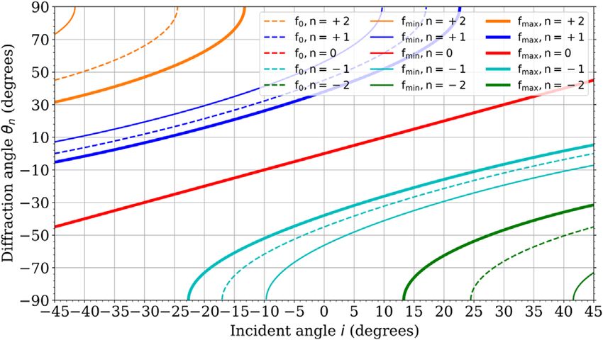
6                                           G. Gao et al.: Acta Acustica 2021, 5, 6

Intensif d’ Aix-Marseille is also acknowledged for granting         10. W. Makinde, N. Favretto-Cristini, E. De Bazelaire: Numer-
access to its high performance computing resources.                     ical modelling of interface scattering of seismic wavefield
                                                                        from a random rough interface in an acoustic medium:
                                                                        comparison between 2D and 3D cases. Geophysical Prospect-
                                                                        ing 53, 3 (2005) 373–397.
References                                                          11. E.G. Loewen, E. Popov: Diffraction Gratings and Applica-
                                                                        tions. CRC Press, 1997.
 1. F. Martini, C.J. Bean, S. Dolan, D. Marsan: Seismic             12. C. Palmer: Diffraction Grating Handbook, 8th ed. MKS,
    image quality beneath strongly scattering structures                2020.
    and implications for lower crustal imaging: numerical simu-     13. M. Born, E. Wolf: Principles of Optics: Electromagnetic
    lations. Geophysical Journal International 145 (2001)               Theory of Propagation, Interference and Diffraction of Light,
    423–435.                                                            7th ed. Cambridge University Press, 1999.
 2. C.J. Bean, F. Martini: Sub-basalt seismic imaging using         14. J.W. Goodman: Introduction to Fourier optics, 4th ed.
    optical-to-acoustic model building and wave equation datum-         Pergamon Press, 2017.
    ing processing. Marine and Petroleum Geology 27 (2010)          15. S. Pinson, J. Cordioli, L. Guillon: Spherical wave reflection in
    555–562.                                                            layered media with rough interfaces: Three-dimensional
 3. F. Martini, C.J. Bean: Interface scattering versus body             modeling. The Journal of the Acoustical Society of America
    scattering in subbasalt imaging and application of                  140, 2 (2016) 1108–1115.
    prestack wave equation datuming. Geophysics 67, 5 (2002)        16. J. Tromp, D. Komatitsch, Q. Liu: Spectral-element and
    1593–1601.                                                          adjoint methods in seismology. Communications in Compu-
 4. O.P. Singh Satpal, D. Sar, S.M. Chatterjee, S. Sawai:               tational Physics 3, 1 (2008) 1–32.
    Integrated interpretation for sub-basalt imaging in Saurash-    17. Z. Xie, R. Matzen, P. Cristini, D. Komatitsch, R. Martin: A
    tra basin, India. The Leading Edge 25, 7 (2006) 882–885.            new PML formulation for coupled fuid-solid problems:
 5. M. Panzner, J.P. Morten, W.W. Weibull, B. Arntsen:                  Application to numerical simulations in ocean acoustics with
    Integrated seismic and electromagnetic model building               solid ocean bottoms. Journal of the Acoustical Society of
    applied to improve subbasalt depth imaging in the faroe-            America 140 (2016) 165.
    shetland basin. Geophysics 81, 1 (2016) E57–E68.                18. F. Auger, P. Flandrin: Improving the readability of time-
 6. P. Beckman, A. Spizzichino: The Scattering of Electromag-           frequency and time-scale representations by the reassignment
    netic Waves from Rough Surfaces. Pergamon Press, Oxford,            method. IEEE Transactions on Signal Processing 43, 5 (May
    1963.                                                               1995) 1068–1089.
 7. F.G. Bass, I.M. Fuks: Wave Scattering from Statistically        19. N. Favretto-Cristini, P. Cristini, E. de Bazelaire: What is a
    Rough Surfaces. Pergamon Press, Oxford; New York, 1979.             seismic reflector like? Geophysics 74, 1 (2009) T13–T23.
 8. J.A. Ogilvy: Theory of Scattering from Random Rough             20. N. Favretto-Cristini, P. Cristini, E. de Bazelaire: Influence on
    Surfaces, Hilger, 1991.                                             the Interface Fresnel zone on the reflected P-wave amplitude
 9. G. Voronovich: Wave Scattering from Rough Surfaces.                 modelling. Geophysical Journal International 171 (2007)
    Springer, 1994.                                                     841–846.

 Cite this article as: Gao G, Cristini P, Favretto-Cristini N & Deumié C. 2021. On the reflection of time-domain acoustic spherical
 waves by a sinusoidal diffraction grating. Acta Acustica, 5, 6.
You can also read