One-Way Fluid Structure Interaction of a Go-Kart Spoiler Using CFD Analysis - MDPI
←
→
Page content transcription
If your browser does not render page correctly, please read the page content below
Proceedings
One-Way Fluid Structure Interaction of a Go-Kart
Spoiler Using CFD Analysis †
Mohammad AL-Rawi 1,* and Abderrahmane Oumssount 2
 1 Centre of Engineering and Industrial Design, Waikato Institute of Technology,
   Hamilton 3240, New Zealand
 2 JP Marshall Engineering, Hamilton 3200, New Zealand; bdulo@marshallprofiling.co.nz

 * Correspondence: Mohammad.al-rawi@wintec.ac.nz; Tel.: +64-(0)7-834-8800 (ext. 3108)
 † Presented at the 13th Conference of the International Sports Engineering Association,
   Online, 22–26 June 2020.

 Published: 15 June 2020

 Abstract: The spoiler on a go-kart is required to prevent the vehicle becoming airborne at speeds of
 80 km/h or more. An optimal spoiler design balances this safety aspect with speed and fuel
 economy. This paper reports the results of a project to improve the aerodynamic aspects of a go-
 kart spoiler design using CFD Analysis. We investigated the design of a rear spoiler with three
 proposed angles ( = 9.5°, = 19.5°, = 29.5°). The drag force produced by each of the three
 designs is compared. Different computational results are discussed such as the air flow velocity,
 pressure and the applied forces in terms of CFD analysis using one-way fluid structure interaction
 (one-way FSI) to determine the spoiler stress, strain and drag coefficient. The findings of this paper
 have implications for the leisure and tourism industries, and may be applicable to other recreational
 vehicles’ spoilers.

 Keywords: go-kart spoiler; FE analysis; CFD modelling; one-way FSI

1. Introduction
     Go-karts are very popular recreational vehicles suitable for a wide variety of ages [1]. The vehicles
must be safe, fuel efficient, but able to obtain sufficient speed to be entertaining to the user. The focus
of current sports engineering research is to improve the efficiency of the aerodynamic shape of the
vehicle and minimize accidents. Given that the kart speed varies from 45–90 km/h, a strong chassis and
rear spoiler prevent the kart from flying at top speed [1]. However, many improvements will impact on
the performance of the kart at the desired speed ranges [2–4]. A rear spoiler acts like plane wings but in
a reversed way: where the plane wings provide lift forces, the spoiler provides down forces. These
down forces allow the vehicles to travel faster and turn corners more safely by increasing the vertical
loads on the tires, thereby increasing the grip. Without a spoiler, the bodyweight of the cart would have
to be increased to prevent it flying off the track, which decreases fuel consumption efficiency. Rear
spoilers also compensate for the adverse effects of the body shape in competitive sports vehicles, where
other elements of the vehicle design are dedicated to enhancing the existing favorable properties of the
vehicle [5,6]. Spoilers also reduce drag forces that may cause vehicle instability and poor handling [5,6].
Much of the literature is devoted to improving the aerodynamic efficiency of spoilers in cars [1–3,5,6].
This paper focuses on aerodynamic efficiency of spoilers applied to go-karts.
     The main objective of this study is to investigate the drag coefficient produced by the spoiler tilted
to one of three different angles:    = 9.5°, = 19.5°, and          = 29.5° with respect to the supports on
the kart (Figure 1). This paper generates and discusses different results for the air flow, pressure and
applied forces obtained by the CFD modeling and the spoiler stress and the drag coefficient obtained
from the FE analysis using the one-way FSI method.

Proceedings 2020, 49, 51; doi:10.3390/proceedings2020049051                www.mdpi.com/journal/proceedings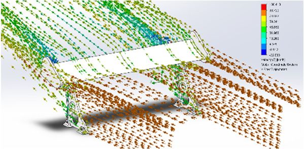
Proceedings 2020, 49, 51                                                                            2 of 6

                               Figure 1. Go-kart project: (Resource Wintec).

2. Materials and Methods

2.1. CFD Setup and Analysis
     In this project, CFD analysis is performed using SolidWorks flow simulation tools. This provides
results for fluid flow velocity, forces and pressure that closely approximate real life events. The
proposed spoiler is constructed in SolidWorks to fit on our go-kart project as shown in Figure 1. The
drawing dimensions for the SolidWorks file are shown in Figure 2, which demonstrates the general
assembly of the 3D model. Three spoiler designs are investigated, each having a different angles of 9.5°,
19.5° and 29.5°, as shown in Figure 3. The designs are compared in terms of drag coefficient to avoid
flying accidents while speeding.

                                 Figure 2. Spoiler dimensions and details.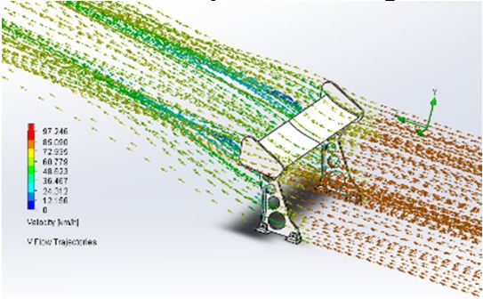
Proceedings 2020, 49, 51                                                                                  3 of 6

       9.5°                              19.5°                             29.5°

                      (a)                               (b)                              (c)

      Figure 3. Types of spoilers investigated with three different angles: (a) 9.5° Spoiler; (b) 19.5°
      Spoiler; (c) 29.5° Spoiler.

     The computational simulation is set to an external flow (Air), and includes gravity in the y-
direction with a value of −9.81 m/s2, and air flow velocity of 80 km/h in the z-direction. The boundary
conditions are set to the following computational domain; x = 1.1933, y = 0.458 and z = 1.0337 m.
Additionally, we set the following goals to monitor and capture the simulation results: average
velocity, forces in x, y and z direction and the drag coefficient, , equation into SolidWorks.

                                                    =                                                     (1)
                                                          2
where, force (F) is in N, fluid density ( ) is in kg/m3, average velocity ( ) is in m/s and the reference
area (A) is in m2. The mesh is set using the global setting with uniform mesh and value of 0.169 m for
the minimum gap size with a 3 ratio factor and the level of initial mesh set to 5. The CFD simulation
generates the air flow results as force impacting on the front face of the spoiler which will be exported
into the FE analysis as a one-way FSI to present the pure mapping of the physical air flow properties.

2.2. FE Analysis
     Finite element analysis (FEA) is the part of the SolidWorks suite of simulation tools that deals
with solid objects. FEA is used to measure the stress and strain on the spoiler due to the air flow
resulting from the CFD analysis. This air flow is imported as an inlet force facing the spoiler using
flow effects option. This will generate fluid shear stress in the x, y and z directions.
     The spoiler material is set to ABS, considered the most realistic material for modelling applying
the cost effectiveness criterion. The material could be modeled as manufactured from fiber glass or
carbon fiber, but these are more expensive materials so unlikely to be applied in most leisure-operator
settings. ABS spoilers are mechanically strong, resistant to cracking or deforming due to the wind
flow forces. Figure 3 shows how the constructed spoiler is modeled fixed at the base support at the
three angles described in Section 2.1 above.
     The FE mesh is set to fine standard type mesh with parameter values: global size (5.25 mm) and
tolerance (0.262 mm) as shown in Figure 4.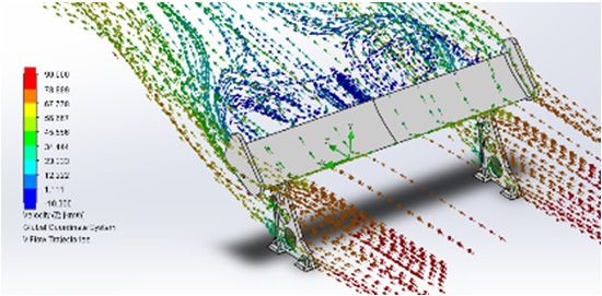
Proceedings 2020, 49, 51 4 of 6
(a) (b)
Figure 4. Mesh for the 9.5° spoiler: (a) side view; (b) isometric view.
3. Results and Discussion
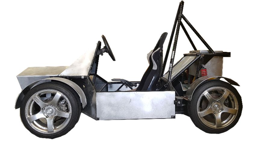
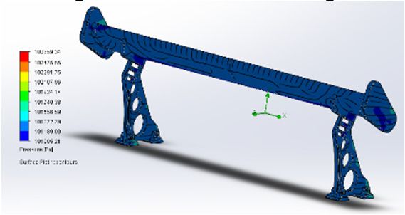
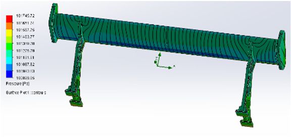
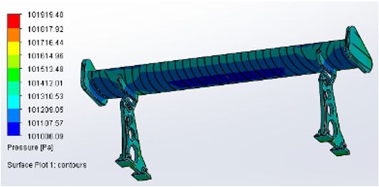
The CFD results for pressure and velocity for the three proposed designs ( = 9.5°, = 19.5°,
and = 29.5°) are shown in Figure 5. This figure demonstrates the pressure impacting on both sides
of the spoiler (front and back) and shows the flow streamline passing the spoiler to calculate the drag
coefficient.
The drag coefficient (Cd) of the same spoiler at three different angles—9.5°, 19.5°and 29.5°—is
investigated and the results of the air flow are exported to the FE Analysis. The air flow is then set
up as an external force impacting on the spoiler using the one-way FSI method. Figure 6 shows the
von Mises stresses (the maximum distortion energy) which indicates the yielding point for the ductile
material for the 9.5° design. This design produces the least drag of the three designs with a Cd of
0.65. Additionally, after passing the spoiler, the air flow kept straight and did not show turbulent
behavior, as shown in Figure 5.
Front pressure on 9.5° spoiler Front pressure on 19.5° spoiler Front pressure on 29.5° spoiler
Back pressure on 9.5° spoiler Back pressure on 19.5° spoiler Back pressure on 29.5° spoiler
Fluid velocity on 9.5° spoiler Fluid velocity on 19.5° spoiler Fluid velocity on 29.5° spoiler
Figure 5. The Air flow simulation around the three designs of spoilers having angles of 9.5°, 19.5° and
29.5°.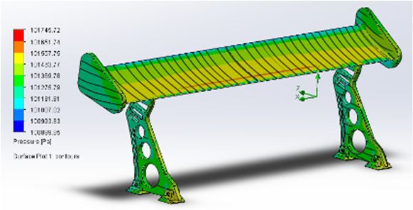
Proceedings 2020, 49, 51                                                                                     5 of 6

      The von Mises stress result is assessed to the maximum yield strength for the ABS material which
should not exceed 30 MPa. From Figure 6, the 9.5° von Mises stress analysis shows that the maximum
is 1.386 MPa, which occurred in the support due to the 4.5 N wind force in the z-direction and 17 N
downward force in the y-direction. The center of the spoiler recorded a 0.36 MPa von Mises stress,
which still did not impact on its structure. For the strain, the highest deflection, 0.48 mm, was recorded
in the center of the spoiler. The supports’ reaction forces to stabilize the spoiler reached 15.654 N, which
is safe as it is greater than the body weight.

                               Figure 6. von Mises stress analysis of 9.5° spoiler.

     The 19.5° spoiler produced the second highest drag between all the designs with a Cd value of
0.89. Figure 5 indicates that the air flow after passing the spoiler had a higher pressure drop from an
atmospheric pressure to 101.19 KPa, and which would create greater turbulence compared to the 9.5°
design.
     The center of the spoiler recorded a 0.4 MPa von Mises stress, which still did not impact its structure.
For the strain, the center of the spoiler recorded the highest deflection, of 0.45 mm. The supports’ reaction
forces to stabilize the spoiler reached 16.8 N, which is safe as it exceeds the body weight.
     Finally, the 29.5° spoiler produced the highest drag between all the designs with a Cd value of
1.26. As with the 19.5° spoiler, the pressure dropped from an atmospheric pressure to 101.19 kPa.
Figure 5 shows the air flow simulation, including where it contains a higher dead zone with a higher
turbulence than the other designs.

4. Conclusions
     In conclusion, a spoiler tilted to one of three different angles relative to the supports is investigated.
The drag coefficient and mechanical properties were analyzed to identify the most suitable angle to
which the spoiler may be tilted on a go-kart operating at a speed of 80 km/h. The most promising design
was the 9.5° angle, which contains the least drag, with a Cd of 0.62, defined within the air flow forces
and the reference area. This design also generates a maximum stress of 1.386 MPa and its minimum
strain is 0.45 mm. The supports’ base reaction force was also the lowest with a drag force of 15.64 N.

References
1.    Akash, C.R.; Tushar, S.; Raghvendra, K.M. Design and Development of Foldable Kart Chassis. In Proceedings of
      the 4th International Conference on Materials Processing and Characterization, Andhra Pradesh, India,
      14–15 February 2015; Volume 2, pp. 1707–1713.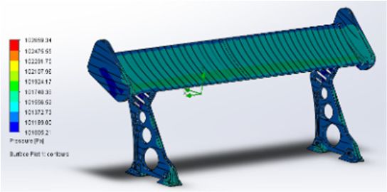
Proceedings 2020, 49, 51                                                                                       6 of 6

2.    Estrada, G. Mercedes-AMG GTR: Aerodynamics for the Record. In Progress in Vehicle Aerodynamics and
      Thermal Management; Wiedemann, J., Ed.; FKFS: Stuttgart, Germany, 2017; Springer: Cham, Switzerland,
      2017; pp.135–144.
3.    Wahl, G. 918 Spyder–the impulse source for future sports car concepts. In Munich Chassis Symposium 2014;
      Springer: Wiesbaden, Germany, 2014; pp. 35–56.
4.    Meder, J.; Wiegand, T.; Pfadenhauer, M. Adaptive aerodynamics of the new Porsche 911 Turbo. In ATZ
      Worldwide 2014; Springer Fachmedien: Wiesbaden, Germany, 2014; Volume 116, pp. 42–45.
5.    Gönüldinc, O.; Hölzel, S. Adaptive Aerodynamik–Innovation des Porsche 911 Turbo; Springer: Wiesbaden,
      Germany, 2014; pp. 159–74.
6.    McBeath, S. Competition Car Aerodynamics, 3rd ed.; Veloce Publishing Ltd.: Bondbury, UK, 2015.

                           © 2020 by the authors. Licensee MDPI, Basel, Switzerland. This article is an open access
                           article distributed under the terms and conditions of the Creative Commons Attribution
                           (CC BY) license (http://creativecommons.org/licenses/by/4.0/).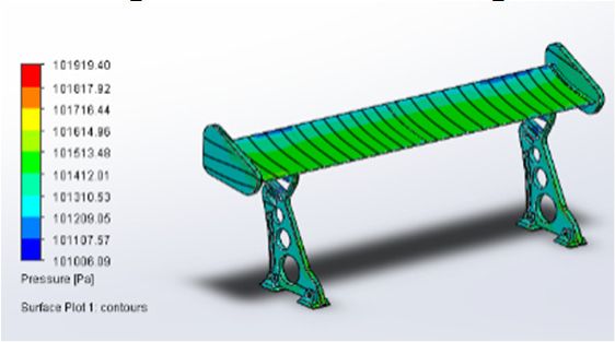
You can also read