Operating Instruction & Manual Harmonia thermal control unit - Cronus-PCS
←
→
Page content transcription
If your browser does not render page correctly, please read the page content below
Operating Instruction & Manual
                        Harmonia thermal control unit

Document date: 2020-04-30
Version 1.1

www.cronus-pcs.com - No guarantee of system performance is assumed from the information provided. Cronus-PCS reserves the right to
make technical changes to the equipment or changes to this document without any prior notice. - P a g e 1 | 17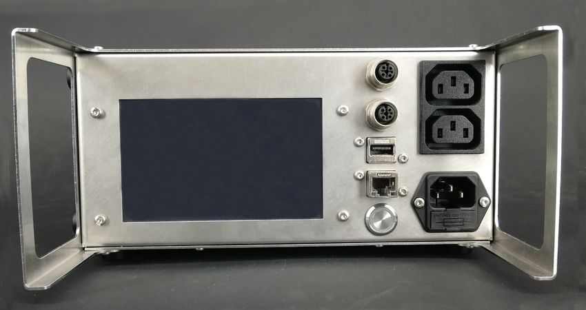
IMPORTANT
At anytime:
• Harmonia MUST operate with heating elements of same voltage as
  the mains supply voltage. Do NOT mix 110 and 230 VAC !!!
• Harmonia MUST be connected to wall power INCLUDING perfect
  ground.
• Electrical-Heating-Blanket (EHB) MUST be mounted tight around a
  vessel INCLUDING the liquid to be heated – which at least cover
  the inner side of the vessel well above the EHB.
• Heating-Support-Foot (HSF) MUST have the OD 3 x 100 mm
  thermocouple installed in the HSF body hole.
• thermocouple MUST be mounted in the vessel INCLUDING the
  liquid in order to be submerged.
• Don’t mix up A and B channels thermocouple and heaters.
• Keep Harmonia out of contact with any liquid.
• Keep the HSF out of contact with any liquid.

www.cronus-pcs.com - No guarantee of system performance is assumed from the information provided. Cronus-PCS reserves the right to
make technical changes to the equipment or changes to this document without any prior notice. - P a g e 2 | 17
Contents
1.0 - Concept overview ........................................................................................................................... 4
   1.1 - Product purpose.......................................................................................................................... 4
2.0 - Device Overview.............................................................................................................................. 4
   2.1 – Harmonia internal design ........................................................................................................... 5
   2.2 – Requirement............................................................................................................................... 5
   2.3 Specification .................................................................................................................................. 5
3. Heating design ..................................................................................................................................... 5
   3.1 Electrical-Heating-Blanket and handling ....................................................................................... 5
   3.2 Heating-Support-Foot and handling.............................................................................................. 6
   3.3 Description of functionality ........................................................................................................... 7
4. Start-up................................................................................................................................................ 7
   4.1 Quick instruction ........................................................................................................................... 8
   4.2 – Harmonia GUI instructions ......................................................................................................... 9
       4.2.1 – Harmonia Cable setup ......................................................................................................... 9
       4.2.2 – Harmonia Main GUI ........................................................................................................... 10
       4.2.3 – Harmonia PID GUI, left and right....................................................................................... 13
       4.2.4 – Harmonia SET GUI, left and right ...................................................................................... 14
5. Communication ................................................................................................................................. 15
   5.1 - Operation principles.................................................................................................................. 15
   5.2 - Wi-Fi connection ....................................................................................................................... 16
   5.3 – LAN IP/TCP connection ............................................................................................................. 16
   5.4 – Software upgrade ..................................................................................................................... 16
   5.5 – Power supply ............................................................................................................................ 16
6. Safety precautions............................................................................................................................. 16
   6.1 Heating elements ........................................................................................................................ 16
   6.2 Documentation ........................................................................................................................... 16
   6.3 Declaration of Conformity ........................................................................................................... 17

www.cronus-pcs.com - No guarantee of system performance is assumed from the information provided. Cronus-PCS reserves the right to
make technical changes to the equipment or changes to this document without any prior notice. - P a g e 3 | 17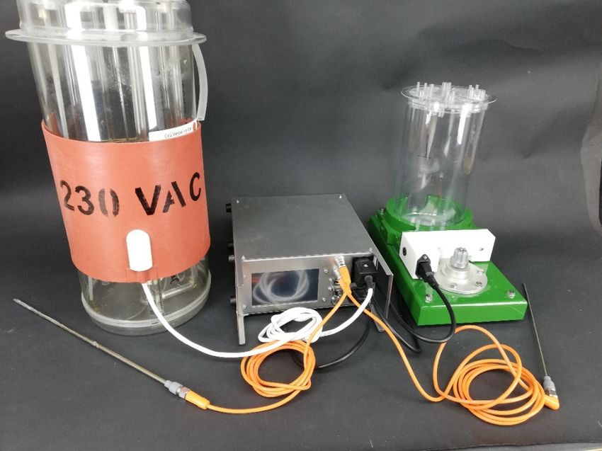
1.0 - Concept overview
Harmonia is a dual channel electrical heating controller for temperature regulation for
endothermic reactions primarily in cultivation of mammalian cell applications with from 0.5
to 50 litre VV / thermal mass. Harmonia is able to work in stand-alone setup or chained with
other Cronus-PCS components.

Harmonia is designed and manufactured by www.cronus-pcs.com

1.1 - Product purpose
The scope of the Harmonia product is:
   • Thermal control of two Single-Use-Bioreactors (SUB) in parallel.
   • The PID control receives the actual process temperature from a thermo couple
       mounted inside (the non-invasive thermo well) each of the two targets.
   • The temperature is regulated by adjusting the electrical energy being added from
       exposing the heating supply to electrical power converted to heat.

2.0 - Device Overview
Harmonia is a product from www.Cronus-PCS.com housed in a Hephaestus U2 cabinet.

The front panel is equipped with:

     1.   TFT 5” colour display
     2.   USB socket for Wi-Fi access
     3.   Button main power breaker
     4.   RJ45 socket for Local-Are-Network (LAN) connection

www.cronus-pcs.com - No guarantee of system performance is assumed from the information provided. Cronus-PCS reserves the right to
make technical changes to the equipment or changes to this document without any prior notice. - P a g e 4 | 17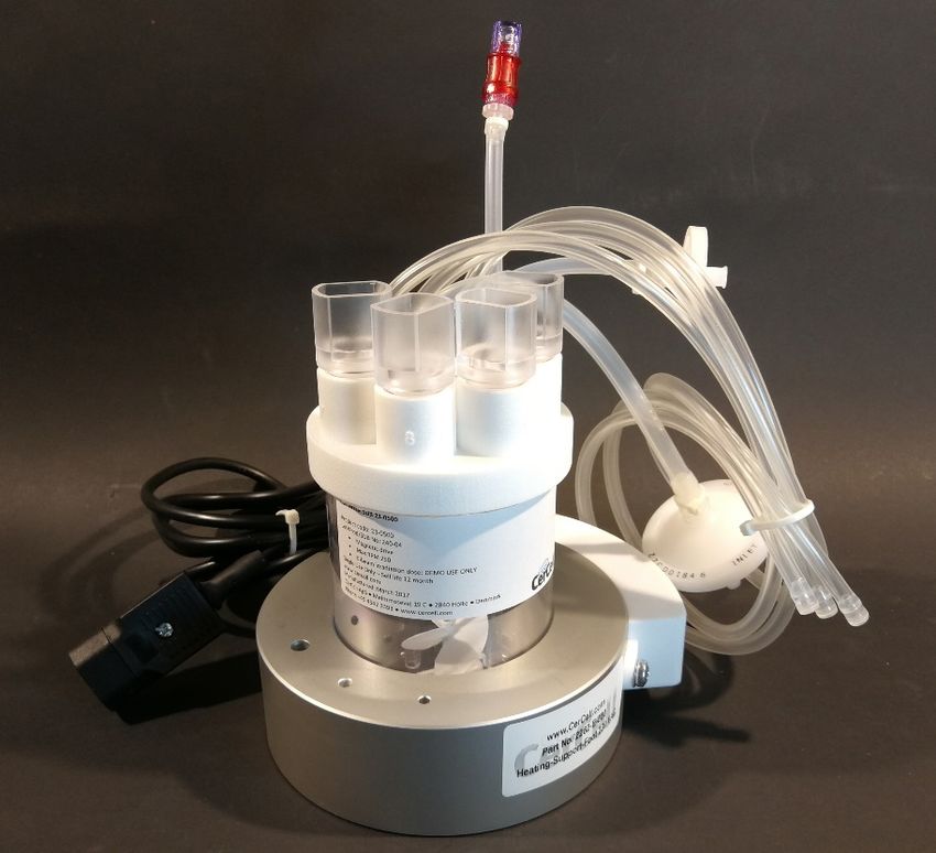
5. Single VAC power inlet, IEC standard male with ground, max 10 amp
     6. Fuse tray, 10 amp, 5x20 mm
     7. Dual VAC controlled power outlet, IEC female socket with ground, Channel A and
        Channel B
     8. Pt100 / Pt1000 sensor input via 4 leg M12 RKF socket – channel B
     9. Pt100 / Pt1000 sensor input via 4 leg M12 RKF socket – channel A

2.1 – Harmonia internal design
Important components inside Harmonia are:
   • Micro-processor transmitter converting the Pt100 / Pt1000 sensor span of ÷20 -
      +150°C to a linear signal (class C sensor is sufficient).
   • Each channel facilitating 110 - 230 VAC supply span with a Crydom 12 amp Solid-
      State-Relay (SSD) breaker generating very little self-heating offering unlimited
      lifetime.

2.2 – Requirement
The unit must be properly installed according to the liquid diagram.

2.3 Specification
When connection to a suitable supply of power the spec is:
                                 External sensor Dual Pt100 or Pt1000
                                  Power breaker SSR 10 amp each channel
                                              GUI 3.5” TFT display
                                Computer power 900 MHz quad-core ARM Cortex-A7 CPU
                                                  running Linux with Code-Sys PLC software
                                      USB socket for Wi-Fi and even charging 5 VDC 1 amp
                                      RJ45socket for IP/TCP via LAN and ModBus
                                    Power supply 230 VAC, max 2,000 watt
                                 Noise level, dBa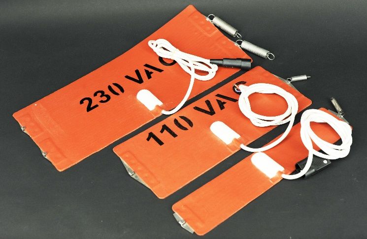
material is an excellent electrical insulator (approx. 12 kV/mm), a good conductor of heat
(7x10⁻⁴ W/cm/K) and flexible. It can withstand continuous temperatures of around 200°C.
The fibre glass weave endows the assembly with good mechanical resistance, while allowing
it to remain very flexible.

Heating blankets for dimension illustration on left, small one mounted on 3.2L vessel right.

Important procedure to follow before Power-On:
   1. Finished filling the SUB with media, mounted on the MST or with HPD drive, all the
      hoses, etc.
   2. Mount the heating blanket to the SUB and do NOT connect the plug to Harmonia IEC
      female socket.
   3. Mount Pt100 sensor via appropriate cables to Harmonia - without the use of tools!
   4. Mount Pt100 sensor by insertion inside the media filled SUB, SUF, SUM
   5. Connection heating blanket plug to Harmonia socket

General precautions:
   • Heating blanket should be mounted tight with full contact to the SUB circumference
   • Thermocouple, Pt100 sensor mounted in the well with some ml glycerine oil for
      better thermal contact and connected to M12-RKF socket.
   • Media has been added to a sufficient height / volume covering ALL of the heating
      blanket.
   • Agitation has started.

Blankets and info available from https://cronus-pcs.com/products/accessories/heating-
blankets/

During operation check daily that the heating blanket is mounted properly and dry.

Whenever there is contact with splashing water or media, interrupt heating operations,
remove the heating blanket from the culture vessel, clean and dry it thoroughly.

3.2 Heating-Support-Foot and handling
The Heating-Support-Foot (HSF) is an aluminum construction allowing the Magnetic-Stirrer-
Table (MST) to insure very stable support, superior agitation and thermal control, and ease

www.cronus-pcs.com - No guarantee of system performance is assumed from the information provided. Cronus-PCS reserves the right to
make technical changes to the equipment or changes to this document without any prior notice. - P a g e 6 | 17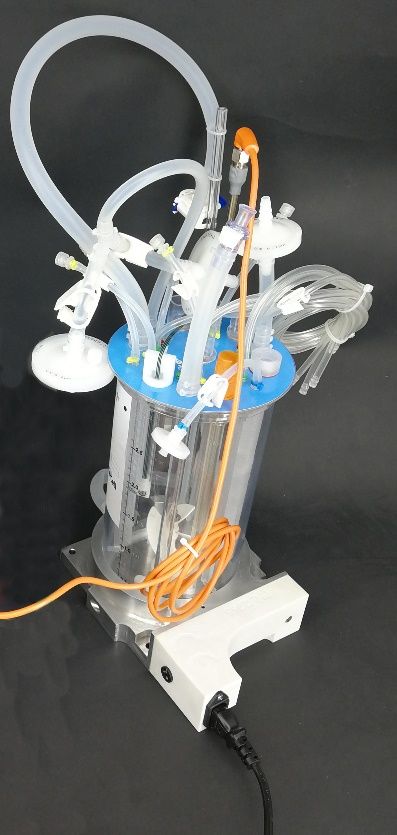
of use. The MST isolates and protects the light weight 500 ml and 3,200 ml (SUB, SUF, SUM)
from the often large and heavy servo motor.
The HSF integrates dual heating elements allowing user to select either 110-120 VAC or 220-
230 VAC supply by rotating a switch. Response time for electrical heating is a 20 degrees
Celsius lift in around 30 minutes. So, if you start at 18°C it takes 30 - 40 minutes to reach
37°C including 1 liter media.

Be sure the voltage selection for the 3,200 / large HSF is the same as the supply voltage !!!!
Check black rotating selected on the white body.

Small HSF for 500 ml at left and the large 3200 ml HSF at right. Note holes for thermocouple.

3.3 Description of functionality
When the process requires energy input (for cultivation) to increase or keep SUB, SUF, SUM
temperature stable the SSD opens sequentially for the electrical heating elements.
   • Precision when correctly tuned PID is better than 0.1°C
   • The program is based on self-tuning functionality which learn and improves accuracy over
       time.
   • Thermal correction is based on Proportional, Integral, and Derivative control loop.

4. Start-up
The scope of the product is to thermally control two bioreactors.

Requirement
The system must be properly installed and connected in accordance with the specifications and
previous information. Operator must also have gained familiarity with the Safety Instructions to be
found separately on www.cronus-pcs.com/support/Safety_Instruction .

www.cronus-pcs.com - No guarantee of system performance is assumed from the information provided. Cronus-PCS reserves the right to
make technical changes to the equipment or changes to this document without any prior notice. - P a g e 7 | 17
Make in particular sure that the 110 or 230 VAC wall plug have a ground connection fully functional.

Harmonia is factory pre-programmed to operate at 37.5 °C and will seek to obtain this temperature
whenever powered up. Changing the set point required simple programming of the unit.

4.1 Quick instruction
The build-in display of Harmonia will inform about possible faults whenever detected.

It takes approximately 1 min after power-on before the regulator is up running.

Sound bibs heard repeatably indicates that the internal battery isn't fully charged, after a while it will
stop automatically.

The regulator is controlled by three constants P, I, D seen by pressing PID on the touch screen.

If e(t) is the difference between the set point and the measured temperature the duty_cycle is
determined by this formula:

 I and D are specified in seconds.
 Every time a dialog window is closed for one of the constant or for the set point the Integral
 is reset.
 For MST two HSF can be used, a small one for up to 500 ml a bigger one for up to 3.2 liter. It
 takes longer time for the 3200 HSF to reach the set point (hours) which is the reason why I
 is very big in order to make the integral part small. But if I is to big the duty_cycle will not
 be big enough when the temperature closes in on the set point. The result can be that the
 temperature suddenly drops for a while until the Integral part takes over.
 To help the user some predefined settings have been made. Can be seen and selected by
 pressing SET. These predefined constants have been found through experiments with 37ºC
 as set point:
 •    500 ml Vessel Volume (VV) tested with 200 ml Working Volume (WV) arranged in
      Heating-Support-Foot (HSF) on Magnetic-Stirrer-Table (MST)
 •    3,200 ml Vessel Volume (VV) tested with 2,000 ml Working Volume (WV) arranged in
      Heating-Support-Foot (HSF) on Magnetic-Stirrer-Table (MST)
 •    30 L (VV) arranged with Electrical-Heating-Blanket blanket
 Cronus-PCS does not give any guarantee with these constants, but anyway its highly
 recommend using these constants as basis for the customers own setup and experiments.

 During turn off or power loss the controller will not immediately turn off it will take 16-60s

www.cronus-pcs.com - No guarantee of system performance is assumed from the information provided. Cronus-PCS reserves the right to
make technical changes to the equipment or changes to this document without any prior notice. - P a g e 8 | 17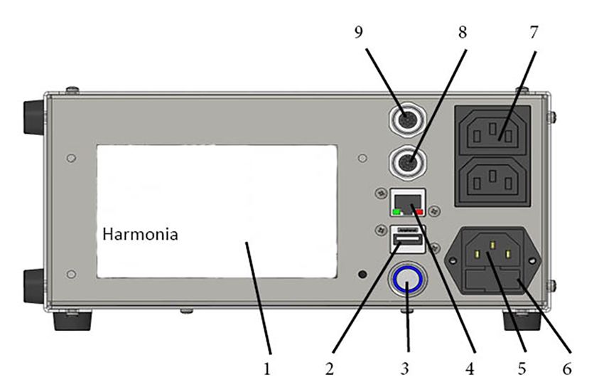
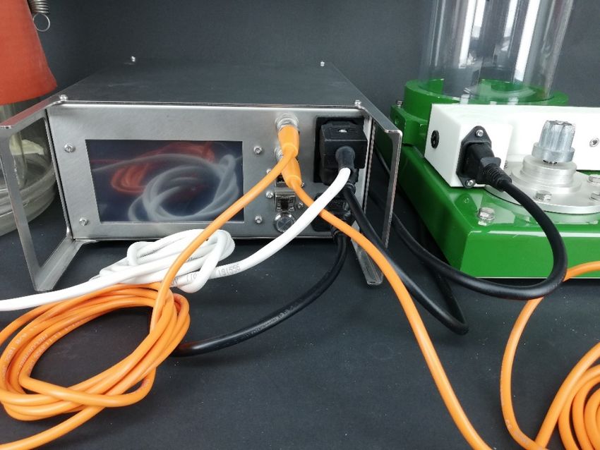
depending on the model. That means a temporarily power loss the regulator will not lose
 its integral state.
4.2 – Harmonia GUI instructions

4.2.1 – Harmonia Cable setup
The first thing you must insure before operating the Harmonia unit is that the
setup is correct. All the cables are connected to the right places, have a look on
the following pictures to get an idea of how it could look like.

How to correctly connect the cables and sensors into Harmonia.

www.cronus-pcs.com - No guarantee of system performance is assumed from the information provided. Cronus-PCS reserves the right to
make technical changes to the equipment or changes to this document without any prior notice. - P a g e 9 | 17

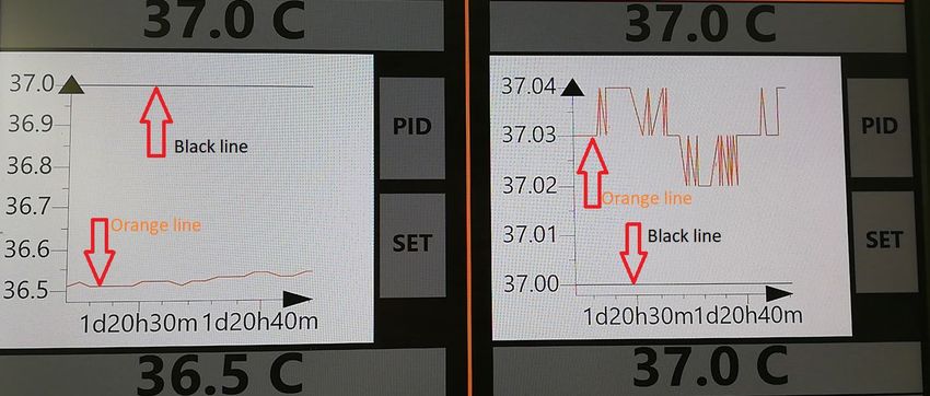
4.2.2 – Harmonia Main GUI
The Harmonia Main GUI is a split screen A (left) and B (Right).

Harmonia Main GUI show on top the two set point value temperatures.

On the picture below you can see, the dynamic temperature diagram where
the orange line is the actual temperature and the black line is the setpoint it
wants to reach. Left side on its way to 37.0 C and right side being 0.04 C from
the setpoint.

Illustrated how a run could look like with the dynamics diagrams.

www.cronus-pcs.com - No guarantee of system performance is assumed from the information provided. Cronus-PCS reserves the right to
make technical changes to the equipment or changes to this document without any prior notice. - P a g e 10 | 17
The bottom of the Harmonia Main GUI shows the measured values in Celsius
and the duty cycle in % of power applied.

Channel A and B with actual temperatures and dutycycles.

On Harmonia Main GUI there you have 3 options:
1 select – change the setpoint
Change the setpoint to what you wish the temperature of your liquid should be
by pressing the grey area under setpoint where the wished temperature will be
shown:

Set point button.
Then a numpad will pop-up:

Numpad to set desired values.
The numpad will show minimum and maximum value. You must be in the
shown range to set a new value. The Back button will erase one character, the

www.cronus-pcs.com - No guarantee of system performance is assumed from the information provided. Cronus-PCS reserves the right to
make technical changes to the equipment or changes to this document without any prior notice. - P a g e 11 | 17
Clear button will clear all the characters, the ESC (Escape) button will close the
numpad without any changes. The OK button will set the new values and close
the numpad if the new values is between the minimum and maximum.

2 select – go to PID manual set value by pressing the PID button

PID button.

Any of the 3 PID parameters are fully accessible and free to program typically
according to requirement of the thermal mass of your system (PID =
Proportional, Integral and Derivative influence).

3 select – go to SET PID point to something we have pre-set in the software to 3
different vessel sizes, by pressing the SET button.

SET button.

www.cronus-pcs.com - No guarantee of system performance is assumed from the information provided. Cronus-PCS reserves the right to
make technical changes to the equipment or changes to this document without any prior notice. - P a g e 12 | 17
4.2.3 – Harmonia PID GUI, left and right

The P, I and D control values to the heating elements can be controlled
manually, by going to the Harmonia PID GUI. It requires some knowledge about
PID control to reach any benefits doing that.
You can set the PID values can be manual selected for both channel A / left and
channel B / right.

Harmonia PID GUI can be both left and right.

1 – To change a value fx P, go press the Change P button:

Change value button.
A numpad will show and then you can change the value.
2 – After you have changed the values you want press the Back button to go
back to Harmonia Main GUI.

www.cronus-pcs.com - No guarantee of system performance is assumed from the information provided. Cronus-PCS reserves the right to
make technical changes to the equipment or changes to this document without any prior notice. - P a g e 13 | 17
4.2.4 – Harmonia SET GUI, left and right

The SET GUI lets you pick pre-set of PID values that we have combined from
testing and knowledge and we recommend using these values to the given
sizes that is defined on the dropdown menu.

Harmonia SET GUI can be both left and right.

1 – to pick one of the recommended pre-set PID constellation you need to
press the arrow on right side:

Selection bar to determined PID values according to vessel size.

www.cronus-pcs.com - No guarantee of system performance is assumed from the information provided. Cronus-PCS reserves the right to
make technical changes to the equipment or changes to this document without any prior notice. - P a g e 14 | 17
2 – And press the vessel size you use:

Selection bar to determined PID values according to vessel size.

3 – When you have selected the reactor you use and thereby the PID
combination it is important that you press, Set Selected Values button,
otherwise the values not be upgraded, changed:

Set Selected Values button.

4- Go back to Harmonia Main GUI by pressing the Back button.

5. Communication
     •    Internal 5” touch sensitive TFT display hooked on the Apollon PLC
     •    External connection to PC, PADs or smart-Phones via Wi-Fi for programming and
          info from the built-in webserver
     •    USB port for USB adapter with software upgrades / Wi-Fi connection
     •    RJ45 port for LAN, ModBus, OPC via IP/TCP and for firmware upgrades and data
          acquisition

5.1 - Operation principles
Assuming a correct assembly of all systems, connections, etc. according to your
Fluid Diagram – check all connections are tight.

www.cronus-pcs.com - No guarantee of system performance is assumed from the information provided. Cronus-PCS reserves the right to
make technical changes to the equipment or changes to this document without any prior notice. - P a g e 15 | 17
5.2 - Wi-Fi connection
When Perseus is equipped with the NetGear Wi-Fi access point the Apache
webhost will be accessible from a browser. Go into “Settings”/ Wi-FI
NETWORKS” and check if you can see Harmonia and select. Return to a browser
and write anything in the address line for access to Apollon.
Harmonia can be controlled via an USB Wi-Fi dongle: SSID: harmoniaXX-cronus
Phrase: cronus-harmonia
5.3 – LAN IP/TCP connection
Check present development status on https://cronus-pcs.com/support/
5.4 – Software upgrade
Check out www.cronus-pcs.com/support/communication/software-upgrade
5.5 – Power supply
CE marked Harmonia operate on AC voltages ranging from 110 and 230 VAC.
6. Safety precautions
Various component require individual attention. Operator must also have gained familiarity with the
Safety Instructions to be found separately on www.cronus-pcs.com/support/Safety_Instruction .
6.1 Heating elements
Danger for electrical shock is highly likely if heating blanket is damaged!
Heating blanket and wiring should be porous, folded, kinked or chipped. The silicone foil should not
be discoloured. This is a sign of short circuiting due to broken heating coils or a defective power cord.
Malfunction and dangerous operating states can occur if damage was overlooked during the pre-
use check.
• If so, switch out the heating blanket and discontinue its use.
Inappropriate cleaning agents or procedures may cause damage. Do not use any cleaning agents or
solvents that can corrode the power supply, silicone foil or silicone foam and make them porous.
• Do not use any hard and / or sharp objects to remove stubborn soiling.
Danger for electrical shock is highly likely if cables, sockets, connectors for both heating blankets
and heating rods is damaged!
6.2 Documentation
Harmonia functionality must be checked on a regular basis and data of such testing kept recorded.
www.cronus-pcs.com - No guarantee of system performance is assumed from the information provided. Cronus-PCS reserves the right to
make technical changes to the equipment or changes to this document without any prior notice. - P a g e 16 | 176.3 Declaration of Conformity
------------------------------
CE Declaration of Conformity
----------------------------------------
Company: Cronus-PCS
-------------------------------
Company address:
Malmmosevej 19C
DK-2840 Holte
www.cronus-pcs.com
--------------------------------------
We hereby declare that based on the design, construction and product placed on the market, the
product designated below fulfils the relevant fundamental safety requirements and health
regulations specified by the pertinent EC Directive.
The declaration shall become legally invalid if any modifications are made to the product, which
have not been certified by Cronus-PCS.
-----------------------------
Designation of the product: Harmonia - p/n 3110
--------------------------------------
Relevant directives of the EC:
• 2006/42/EC Machinery
• 2004/108/EC Electromagnetic Compatibility
• 2006/95/EC Electrical equipment designed for use within certain voltage limits
• 97/23/EC Pressure Equipment
-------------------------------------------
Date of signature: 2020-04-20
----------------------------------------
Function of Signature
Per Stobbe
CEO and Director of R&D
-----------------------------------
www.cronus-pcs.com - No guarantee of system performance is assumed from the information provided. Cronus-PCS reserves the right to
make technical changes to the equipment or changes to this document without any prior notice. - P a g e 17 | 17You can also read