OPERATORS GUIDE I-TEC MINI SERIES - GUIDE DE L'OPÉRATEUR POUR LA SÉRIE I-TEC MINI I-TEC MINI BEDIENUNGSANLEITUNG SERIE I-TEC MINI GUÌA DEL ...
←
→
Page content transcription
If your browser does not render page correctly, please read the page content below
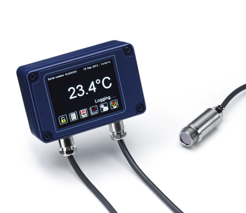
I-Tec Mini Series
Operators Guide

       Guide de l’opérateur pour la série I-Tec Mini
                   I-Tec Mini Bedienungsanleitung
                 Serie I-Tec Mini GuÌa del operario
             Serie I-Tec Mini Manuale di istruzione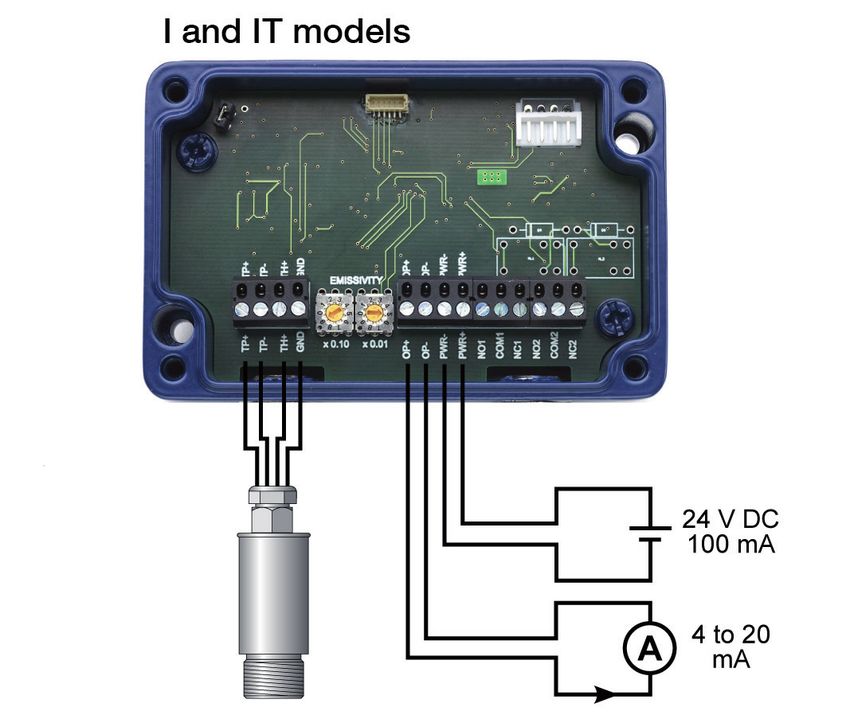
english

          The I-Tec Mini Series is a range of miniature non-contact infrared temperature sensors
          with separate electronics modules.
          All models have an adjustable emissivity setting and are capable of measuring a wide
          variety of target materials, including food, paper, textiles, plastics, leather, tobacco,
          pharmaceuticals, chemicals, ruMBer, coal and asphalt.
          The optional touch screen interface provides temperature indication, alarms, sensor
          configuration and data logging to MicroSD Card. The optional high-temperature
          sensing head may be used in ambient temperatures of up to 180°C without cooling.
          The low-noise cable on high ambient temperature models is resistant to interference
          from movement, so it is ideal for mounting on moving objects such as robot arms.
          A choice of optics are available to measure small or large targets at short or long
          distances, and there is a choice of 4-20 mA, RS485 Modbus and alarm relay outputs.

          SPECIFICATION

          GENERAL
          Temperature Range                           See table of Model Numbers
          Maximum Temperature Span (-IT models)       1020°C
          Minimum Temperature Span (-IT models)       100°C
          Output                                      4 to 20 mA or RS485 Modbus
          Field of View                               See table of Model Numbers
          Accuracy                                    ± 1°C or 1%, whichever is greater
          Repeatability                               ± 0.5°C or 0.5%, whichever is greater
          Emissivity Setting Range                    0.20 to 1.00
          Emissivity Setting Method                   -I models: via two rotary switches in electronics
          module
                                                      -MB and -BT models: via RS485
                                                      -IT and -BT models: via touch screen
          Response Time, t90                          240 ms (90% response)
          Spectral Range                              8 to 14 μm
          Supply Voltage                              24 V DC ± 5%
          Maximum Current Draw                        100 mA
          Maximum Loop Impedance                      -I and -IT models: 900 Ω (4 to 20 mA output)
          Alarm Relays (-IT models)                   2 x Single Pole Changeover alarm relays rated
                                                      24 V DC, 1 A, isolated 500 V DC

          MECHANICAL
                           Sensing head                       Electronics Module
          Construction     Stainless Steel 316                Die-cast Aluminium
          Major Dimensions Ø18 x 45 mm                        98(w) x 64(h) x 36(d) mm
          Mounting         M16 x 1 mm thread                  Two M4 screws for wall mounting (see
                                                              diagram)

          Cable Length (sensing head to electronics module)   1 m (standard), up to 30 m (optional)
          Weight with 1 m Cable                               390 g (approx)
          Cable Connections                                   Removable screw terminal blocks (see
                                                              Connections). Conductor size: 28 AWG to
                                                              18 AWG
          Output Cable Gland                                  Suitable for cable diameters 3.0 to 6.5 mm
  ›2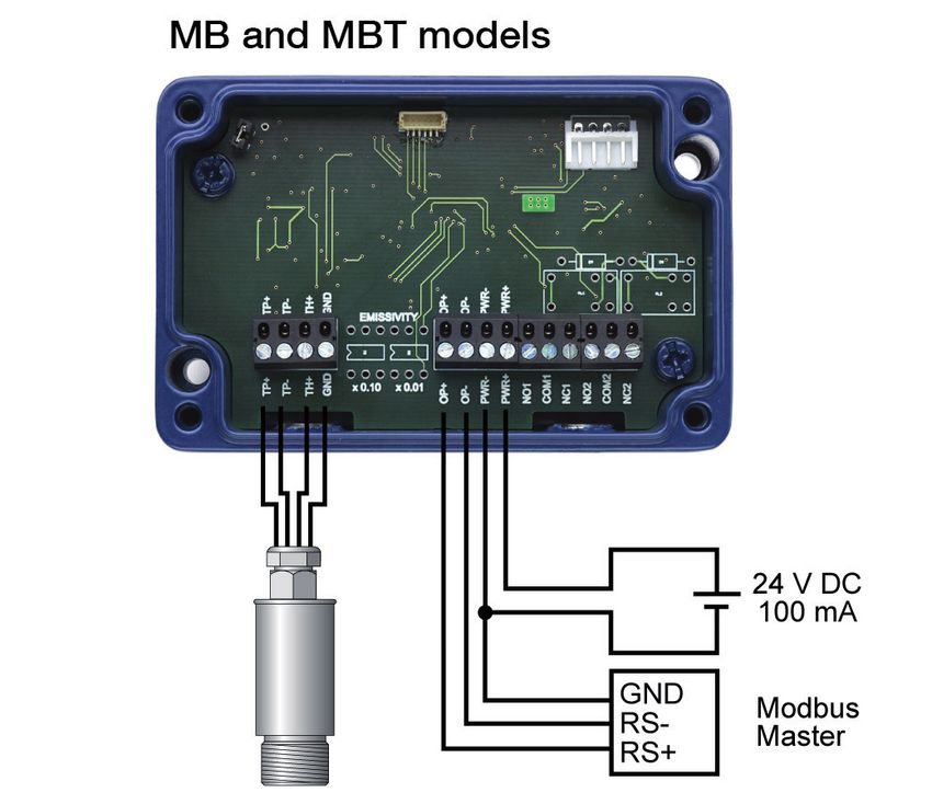
english
ENVIRONMENTAL
                           Sensing Head           Electronics Module     Electronics Module
                                                  (without touch         (with touch screen)
                                                  screen)
Environmental Rating       IP65 (NEMA 4)          IP65 (NEMA 4)          –
Ambient Temperature        See table of Model     0°C to 60°C            0°C to 60°C
Range                      Numbers
Relative Humidity          Maximum 95%            Maximum 95%            Maximum 95%
                           non-condensing         non-condensing         non-condensing
CE Marked                  Yes                    Yes                    Yes
RoHS Compliant             Yes                    Yes                    Yes

ELECTROMAGNETIC COMPATIBILITY STANDARDS:
Class                    Standard                   Description
EMC Directive            EN61326-1:2006             Electrical equii-Tec Minient for measure-
                                                    ment, control and laboratory use – Industrial
- Immunity               IEC 61000-4-2              Electrostatic Discharge Immunity
                         IEC 61000-4-3              Electromagnetic Field Immunity
                         IEC 61000-4-4              Burst Immunity
                         IEC 61000-4-5              Surge Immunity
                         IEC 61000-4-6              Conducted RF Immunity
- Emissions              EN 55022A                  RF Emissions Class A
                         EN 55022B                  RF Emissions Class B

MODEL NUMBERS
The following combinations of ambient temperature range, optics, measured temperature range,
output and interface are available on I-Tec Mini sensors:

                Sensing Head                              Measurement
                                                                                  Output and
  Series          Operating           Field of View       Temperature
                                                                                   Interface
              Temperature Range                             Range
                                                                  LT
                                                                  MT
                                            102                                         I
                                                                  HT
                                            115                   XT
                      MT
                                            130
                                            CF                                        IT
                                                                  CT                 MB
 I-Tec Mini                                                                          MBT
                                                                  HT
                                                                                        I
                                                                  XT
                      HT                    120                                       IT
                                                                  CT                 MB
                                                                                     MBT

                                                                                                    3
                                                                                                        ›
english
SENSING HEAD OPERATING TEMPERATURE RANGE
-MT 0°C to 60°C
-HT 0°C to 180°C
The high ambient temperature sensing head on -HT models is capable of withstanding temperatures
of up to 180°C without cooling. It is available with 20:1 optics.
There is no need to supply cooling air or water, and the miniature sensing head is much smaller than
bulky, cooled sensors.
FIELD OF VIEW
Distance: Sensor to object (inches) Distance: Sensor to object (inches) Distance: Sensor to object (inches)
0 4 8
Spot Dia.
Spot Dia.
0 19.7 39.4
Spot Dia.
0 19.7 39.4
(inches)
(inches)
(inches)
4.4
2.4 3.1 2.5
1.8 1.5
0.5 0.5 0.5
D:S 2:1 D:S 15:1 D:S 20:1
11.9 11.9 11.9
Spot Dia.
Spot Dia.
Spot Dia.
45.2 36.9
(mm)
(mm)
(mm)
61.9 61.9
78.6
111.9
0 100 200 0 500 1000 0 500 1000
Distance: Sensor to object (mm) Distance: Sensor to object (mm) Distance: Sensor to object (mm)
-102 -115 -120
Distance: Sensor to object (inches) Distance: Sensor to object (inches)
0 3.9 7.9
Spot Dia.
0 19.7 39.4
Spot Dia.
(inches)
(inches)
1.1 1.8
0.5 0.5 0.20 0.49
Diameter of target
spot measured versus
D:S 30:1
11.9
Spot Dia.
11.9 5.0 12.5
Spot Dia.
distance from sensing
28.6
(mm)
45.2
(mm)
0 500 1000 0 100 200 head at 90% energy
Distance: Sensor to object (mm) Distance: Sensor to object (mm)
-130 -CF5
MEASUREMENT TEMPERATURE RANGE (°C)
-LT
-MT
-HT
-XT
-CT
-20 0 100 250 500 1000
Fixed (e.g. -MT: 0°C @ 4 mA, 250°C @ 20 mA)
-IT models: 4 to 20 mA output configurable within this range
-MBT and -MB models: Digital output, full temperature range
OUTPUT AND INTERFACE
-I 4 to 20 mA output, no touch screen
-IT 4 to 20 mA output and two alarm relay outputs, with touch screen
-MB RS485 Modbus output, no touch screen
-MBT RS485 Modbus output and two alarm relay outputs, with touch screen
›4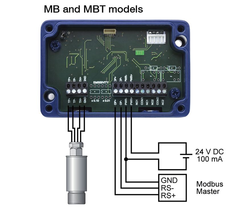
english
EXAMPLE: I-TEC MINI-MT-130-CT-MBT

 Series           Sensing Head          Optics        Temperature             Output and
                  Operating                           Range                   Interface
                  Temperature
 I-Tec Mini       -MT 0°C to 60°C       -130 30:1     -CT configurable        -MBT RS485 Modbus
 I-Tec Mini                             divergent     within the limits:      output and two alarm
                                                      -20 to 1000 °C          relay outputs, with
                                                                              touch screen

EMISSIVITY ADJUSTMENT (-I MODELS)
The emissivity setting on I-Tec Mini -I models may be adjusted via two rotary switches inside the
electronics box. To adjust the emissivity setting:

Set the left switch to the first digit after the decimal point (0.1).
Set the right switch to the second digit after the decimal point (0.01).

To enter an emissivity setting of 1.00, set both switches to 0.

The minimum emissivity setting is 0.2. If a lower emissivity setting is selected, the sensor will default
to an emissivity setting of 0.95.

For example:

 Left switch                        Right switch                       Emissivity setting

 6                                  3                                  0.63

 0                                  0                                  1.00

TOUCH SCREEN (-IT AND -MBT MODELS)
The optional backlit touch screen interface mounted in the lid of the electronics module provides a
large, bright display of the measured temperature, as well as options for full configuration of the
sensor. The graph view shows the history of the measured temperature.

In alarm conditions, the display changes colour to provide an immediate and obvious alarm
indication. Alarm modes and levels can be configured via the touch screen.

TOUCH SCREEN SPECIFICATIONS
Touch Screen Display Format          2.83” (72 mm) resistive touch TFT, 320 x 240 pixels, backlit
Configurable Parameters              Temperature range, temperature units, emissivity setting,
                                     reflected energy compensation, alarms, signal processing,
                                     Modbus address (-MBT models), date and time, data logging
Temperature Units                    °C or °F configurable
Temperature Resolution               0.1°
Alarm Configuration                  Two alarms with adjustable level, individually configurable as
                                     HI or LO. Alarm 2 can be set to target temperature or sensing
                                     head internal temperature
Signal Processing                    Average, peak hold, valley hold, minimum, maximum

                                                                                                            5
                                                                                                                ›
english

          USER INTERFACE

          Default View   Temperature View
                         Displays a large indication of the measured temperature. The background
                         turns bright red when an alarm is activated.

          Setting        Press “°C” to switch to °F and vice versa. The units are changed throughout
          Temperature    the interface.
          Units

          Selecting      Press the temperature display to select which reading is shown:
          Displayed      Filtered Temp
          Temperature    The measured temperature, with averaging and hold processing. This
                         temperature is output by the sensor on the 4 to 20 mA output (-I and -IT
                         models).

                         Average Temp
                         The measured temperature with averaging but without hold processing.

                         Unfiltered Temp
                         The unprocessed measured temperature.
                         MicroSD Card status.

                         This icon is displayed when an SD card is inserted, and flashes when data
                         logging is in progress.

                         This icon is displayed when scheduled data logging is enabled and has yet
                         to begin.

                         List View
                         Displays a list of the measured temperatures, alarm state and data logging
                         state.

                         Filtered Temp: The measured temperature, with averaging and hold
                         processing.

                         Unfiltered Temp: The unprocessed measured temperature.

                         Average Temp: The Unfiltered Temperature averaged over the period
                         specified in “Output Processing”.

                         Maximum Temp: The highest temperature measured during the hold period,
                         with averaging.

                         Minimum Temp: The lowest temperature measured during the hold period,
                         with averaging.

                         Sensor Temp: The internal temperature of the sensing head.

                         Reflected Temp: The reflected energy compensation temperature, as
                         specified in “Emissivity and Compensation”.

  ›6
english
Lock/Unlock
Prevents settings being changed via a four-digit numerical code.
The default password is 1234.
Change Password
Enter, confirm and save a new four-digit code.
Start/Stop Logging
Manually begins or ends data logging (requires MicroSD Card, available
separately).
If Scheduled Start is enabled in Settings > Data Logging, then logging cannot
be started manually.
To manually start logging, you must first disable Scheduled Start.
Graph
Displays the recent history of the Filtered Temperature and the Sensor
Temperature. To scroll backwards and forwards in time, touch the graph and
drag it. The graph stores the most recent 24 hours of temperature data.
Reset Graph
Clears and restarts the graph.
Real-Time Scrolling View
Returns the graph to the real-time scrolling view, showing the most recent
measurements.
Acknowledge Alarms
Switches the relay outputs for triggered alarms to their normal, untriggered
state. The background of the Temperature View, List View and Graph View
will stay red, and the alarms will not be triggered again, until the alarms are
reset (see “Alarms” below). Alarms can be acknowledged when the display
is locked.
Settings
Access the configuration parameters. Press Apply to save the settings,
or Exit to leave the screen without saving.
7
›english
SETTINGS
Date & Time
Change the date and time for data logging purposes. The clock is reset when
the power is cycled unless a battery is fitted.
Output Processing
Averaging Set the time, in seconds, over which the measured temperature is averaged.
Period Note: averaging prevents the sensor from following rapid temperature
changes. Minimum: 0 (no averaging). Maximum: 60.
Hold Mode Peak
The sensor holds the maximum temperature steady for the Hold Period.
After this, the sensor responds normally. If the sensor detects a higher
temperature, it holds this temperature steady for the Hold Period.
Valley
Similar to Peak Hold mode except that the sensor outputs the minimum
detected temperature steady for the Hold Period.
Off
Disables hold processing.
Hold Period Set the time, in seconds, for the sensor to hold the temperature as above.
Minimum: 0 (no hold processing). Maximum: 1200.
Data Logging
Sample The time, in seconds, between samples. Minimum: 1. Maximum: 86,400
Period (1 day).
Number of The number of samples to collect before logging stops. Minimum: 0
Samples (continuous logging). Maximum: 86,400 (1 day of data if Sample Period = 1
second).
Enable The sensor begins logging at the Date and Time specified. Logging can also
Scheduled be started and stopped manually.
Start
Date and The date and time for scheduled logging to start.
Time
›8SETTINGS (continued)
english
Emissivity and Compensation
Emissivity Enter the emissivity of the target. Target emissivity can be determined
Setting experimentally, or estimated using an emissivity table. For more information,
contact I-Tec. Minimum: 0.2. Maximum: 1.0.
Enable If enabled, compensates for errors caused by reflected energy from hotter or
Reflected colder objects.
Energy
Compensation
Reflected Enter the temperature of the surroundings of the target for Reflected Energy
Temperature Compensation. Minimum: -20°C. Maximum: 1000°C.
4 to 20 mA Output (-IT models)
Set the temperature range limits for the 4 to 20 mA output.
Temperature The lower temperature range limit. Minimum: -20°C. Maximum: 900°C.
at 4 mA
Temperature The upper temperature range limit. Minimum: 80°C. Maximum: 1000°C.
at 20 mA
Please note The difference between the temperatures at 4 mA and at 20 mA must be at
least 100°C. The temperature at 20 mA must be greater than the temperature
at 4 mA.
Modbus Address (-MBT models)
Modbus The current Modbus address of the sensor is displayed. Enter a new address,
Address then press Apply to save it to the sensor. Cycle the power to use the new
address.
Minimum: 1. Maximum: 247.
Alarms
Configure the settings for Alarm 1 and Alarm 2 separately, and configure
alarm logging settings.
Manually Reset Alarms
If an alarm has been triggered, allows both alarms to be triggered again.
Alarms will not be triggered again until they are reset, either automatically or
manually.
9
›english
SETTINGS > ALARMS
Alarm 1 and Alarm 2
Alarm Set The temperature at which the alarm is triggered. Minimum: -20°C. Maximum:
Point 1000°C.
Hysteresis The temperature difference between the Alarm Set Point and the reset
temperature. Hysteresis is only used when Automatic Reset is enabled.
Please see the diagrams below for more information
Minimum: 0°C (hysteresis disabled). Maximum: 1000°C.
Filtered Select the temperature monitored by Alarm 2.
Temperature
or Sensor
Temperature
(Alarm 2 only)
Alarm Type High
The alarm is triggered when the temperature rises above the Alarm Set Point.
Low
The alarm is triggered when the temperature drops below the Alarm Set
Point.
Off
The alarm is disabled.
Reset Automatic
The alarm is acknowledged and reset automatically when the temperature
reaches the reset temperature (see Hysteresis). It can also be acknowledged
or reset manually.
Manual
The alarm is acknowledged by pressing Acknowledge on the
Temperature View or List View, and reset by pressing Reset on the
Alarms screen.
Alarm Logging
Alarm events can be logged to the MicroSD Card. Alarm log files and settings
are independent from Data Logging.
Log Trigger The time that an alarm is triggered will be logged.
Time
Log Data Data logging will start when an alarm is triggered. 1 sample is logged per
While second. Logging stops when both alarms are reset.
Triggered
Log The time that the alarm is acknowledged will be logged.
Acknowledge
Time
Log Reset The time that the alarm is reset will be logged.
Time
› 10english
ALARM OPERATION WITH HYSTERESIS & AUTOMATIC RESET
High Alarm with Automatic Reset Low Alarm with Automatic Reset
Temperature Temperature
Alarm Set Point
Hysteresis
Hysteresis
Alarm Set Point
Time Time
Alarm triggered Alarm reset Alarm triggered Alarm reset
DATA LOGGING (-IT AND -MBT MODELS)
The I-Tec Mini can be used as a standalone data logger.
I-Tec Mini models -IT and -MBT include a MicroSD card slot for data logging, which can be
configured via the touch screen interface. The user can select the sample rate and the number of
samples to be taken and schedule the data logging to start at a certain time.
With a 2 GB card, the user can store 28.4 million readings, which provides almost 1 year’s worth
of data at the fastest possible sample rate of 1 per second.
Data is stored on the MicroSD card in .csv format and can be viewed and edited easily using
spreadsheet software.
A MicroSD card with SD card adapter is available as an optional accessory.
The MicroSD card slot and battery holder are located on the touch screen circuit board in the
lid of the I-Tec Mini. Readings are time and date stamped using the sensor’s internal clock. The
clock is reset when the power is disconnected, or it will continue if the optional battery is fitted.
DATA LOGGING SPECIFICATIONS
Data Logging Interval 1 to 86,400 seconds (1 day)
MicroSD Card Max. capacity: 2 GB (not included)
Internal Clock Battery 1 x BR 1225 3V (not included)
Variables Logged Target temperature, sensing head temperature, electronics module temperature,
max, min, average, emissivity setting, reflected energy compensation temperature
File format .csv
Configurable Parameters Sample period, number of samples, scheduled start date and time
Modbus address range 1 to 247
USING THE I-TEC MINI AS A DATA LOGGER
1. Insert a MicroSD card into the holder on the circuit board inside the lid of the I-Tec Mini electronics module.
2. To retain the date and time when the I-Tec Mini is switched off, fit a battery to the holder on the
circuit board inside the lid.
3. Replace the lid and connect the sensor power supply.
4. To set the number of samples to be logged, the time period between samples, and, if required,
to schedule data logging to automatically start, press to access the Settings menu, then
press to access the Data Logging options.
5. To save data logging settings, press
6. To manually start data logging, press on the Temperature View or List View.
7. While logging is in progress, the logging icon flashes on the Temperature View and List View.
8. To stop data logging, press .
9. To transfer data to a computer, remove the MicroSD Card from the sensor, insert the card into
the SD Card adapter (supplied with MicroSD Card, accessory model SPLOG) and insert the
adapter into an SD Card reader.
Note: MicroSDHC Cards are not compatible with the I-Tec Mini.
11
›english
INSTALLATION OF MICROSD CARD AND BATTERY
MicroSD Card
Battery
(use 1 x BR 1225 3V)
DATA LOG FILES
Data is saved to the MicroSD Card in .csv format. This file format can be opened or imported by
spreadsheet software such as Microsoft Excel.
A new folder is created on the MicroSD Card for each day that data is logged.
A new log file is created every time logging is started. The start time is used as the file name.
DIMENSIONS
Electronics Module Sensing Head Mounting Nut
(included)
98 ø 18.6 ø 18 Thread M16 x 1 mm 4
86 Mounting
holes: use M4
CSK screws
(supplied)
Standard length: 12
Touch screen 1000 13 45 18
64 (optional) 36
72 mm (2.83")
Air Purge Collar Removable spigot fitted to
1/8" BSP type APSN for use with
air fitting -151, -201, -301 and -CF
18 models. Not fitted to type
20 Cable glands:
14 mm AF APSW for -21 models.
48 ø 40 ø 29
36
25
18
50
› 12english
Fixed Mounting Bracket (FBS) Adjustable Mounting Bracket (ABS)
15
M16 Clearance
10
9
60° Rotation
40
40
50 25 50 25
48
2 x Mounting Holes M4 Clearance 2 x Mounting Holes M4 Clearance
24 24
9 9
60° Rotation 60° Rotation
ACCESSORIES
A range of accessories to suit different applications and industrial environments is available. These
may be ordered at any time and added on-site. The following accessories are available from I-Tec:
Fixed mounting bracket (see above for dimensions): Allows rotational adjustment in one
dimension. Model number: FBS.
Adjustable mounting bracket (see above for dimensions): Allows rotational adjustment in two
dimensions. Model number: ABS.
Air purge collar (see above for dimensions): The air purge collar is used to keep dust, fumes,
moisture, and other contaminants away from the lens. It must be screwed fully onto the
sensing head. Air flows into the 1/8” BSP fitting and out of the front aperture. Air flow should
be 5 to 15 l/min. Clean or ‘instrument’ air is recommended. Model APSW is for use with
sensors with 2:1 optics. Model APSN is for use with all other I-Tec Mini models.
Laser sighting tool: When fitted to the sensor during installation or re-alignment, the laser
sighting tool pinpoints the centre of the measured spot. Model number: LSTS.
MicroSD Card: Stores logged data. For use with -MBT and -IT models. Includes SD Card
adapter. Model number: SPLOG.
OPTIONS
The following options are available. Options are factory installed and must be ordered with the
sensor.
Calibration Certificate: UKAS traceable certificate showing the measured temperature at
three points across the sensor’s temperature range. Model number: CALCERTA.
Extended Cable (30 m maximum total cable length): 1 m cable is supplied with each sensor
as standard. Extra cable can be added to this in increments of 1 m. Model number: VKVL
(-MA models), VKVLHT (-HA models).
13
›english
INSTALLATION
The installation process consists of the following stages:
Preparation Mechanical installation Electrical installation
Please read the following sections thoroughly before proceeding with the installation.
PREPARATION
Ensure that the sensor is positioned so that it is focused on the target only.
DISTANCE AND SPOT SIZE
The size of the area (spot size) to be measured determines the distance between the sensor and
the target. The spot size must not be larger than the target. The sensor should be mounted so
that the measured spot size is smaller than the target.
AMBIENT TEMPERATURE
The I-Tec Mini is available with a choice of two miniature sensing heads, for use in low or high
ambient temperatures:
-MA models: The sensing head is designed to operate in ambient temperatures from 0°C to 60°C.
-HA models: The sensing head is designed to operate in ambient temperatures from 0°C to
180°C. No cooling is required, which saves the energy and cost of supplying air or water to
cool the sensor.
Avoid thermal shock. Allow 20 minutes for the unit to adjust to large changes in ambient
temperature.
ATMOSPHERIC QUALITY
Smoke, fumes, dust or steam can contaminate the lens and cause errors in temperature
measurement. In these types of environment the air purge collar should be used to help keep the
lens clean.
INTERFERENCE FROM MOVEMENT
The low-noise sensing head cable on -HA models is resistant to interference caused by movement.
The sensing head may be mounted on moving machinery such as robot arms without affecting the
accuracy of the measured temperature.
ELECTRICAL INTERFERENCE
The I-Tec Mini is tested to industrial standards for electromagnetic compatibility (EMC) as shown in
Specifications at the beginning of this manual.
› 14To minimise electromagnetic interference or ‘noise’, the sensor should be mounted away from
english
motors, generators and such like.
POWER SUPPLY
Be sure to use a 24 V DC (100 mA) power supply.
MECHANICAL INSTALLATION
All sensors come with a 1 m cable and a mounting nut as standard. Longer cables are available to
order. The sensor can be mounted on brackets or cut-outs of your own design, or you can use the
fixed or adjustable mounting bracket accessories.
Note: The sensor housing must be connected to earth at one point, either the housing of the
sensing head, the electronics module, or the output cable shield termination. To avoid ground
loops, please ensure the sensor is grounded at only one of these points.
ELECTRICAL INSTALLATION
CONNECTIONS
Sensing Head Cable
Colour Codes (all models): PWR+
TP+ Blue with white line PWR-
TP- White with blue line
OP-
TH+ Blue
GND White
OP+
PWR+
PWR-
PWR-
OP-
OP+
15
›english
WIRING (ALL MODELS)
Check the distance between the sensing head and the electronics module, and between the
electronics module and the instrumentation. If necessary, the sensor can be ordered with a longer
cable between the sensing head and the electronics module.
The output cable from the electronics module should have an outer diameter between 3.0 and 6.5
mm, with conductors of size 28 to 18 AWG.
The terminal blocks in the electronics module may be removed from the circuit board for easy
wiring.
Do not disconnect the touch screen circuit board from the main circuit board while the sensor is on.
WIRING (-MB AND -MBT MODELS)
When connecting several sensors in a single Modbus network, all of the sensors should be
connected via a junction box to a single network bus cable, running from the furthest sensor to the
Modbus Master.
Up to 247 sensors may be connected to a single Modbus network. Each sensor must have a
unique Modbus address. I-Tec Mini sensors are normally shipped with Modbus address 1. The
Modbus address may be changed via the touch screen interface on -MBT models, or via Modbus.
To help prevent data reflections, please ensure the cable between each sensor and the main
network bus is as short as possible. The network bus should be terminated with a resistor of 120Ω
between the RS+ and RS- wires. The PWR- wire of the bus should be connected to the signal
ground of the Modbus Master.
MODBUS OVER SERIAL LINE (RS485)
Interface
Baud rate 9600
Format 8 data, No parity, 1 stop bit
Reply delay (ms) 20
Supported functions
Read register 0x03, 0x04
Write single register 0x06
Write multiple register 0x10
Mask write register 0x16
Read/write 0x17
The list below includes all available addresses:
R = Read
W = Write (single, multiple or read/write)
MW = Mask write
Address Length Description R/W/MW
(words)
0x00 1 MODBUS slave address R/W*
0x02 2 Sensor identification register R
Bits 0..19 - Serial number
Bits 20..23 - Sensor type (12 = I-Tec Mini)
Bits 24..26 - Sensor field-of-view
For MA : 0 = 2:1, 1 = 15:1, 2 = 30:1
For HA : 0 = 20:1
Bits 28..32 - Reserved
› 16english
Address Length Description R/W/MW
(words)
0x06 1 Unfiltered object temperature R
0x08 1 Sensor temperature R
0x0A 1 Maximum temperature over hold period R
0x0C 1 Minimum temperature over hold period R
0x0E 1 Average temperature over hold period R
0x10 1 Filtered object temperature R
0x12 1 PI temperature R
0x14 1 Emissivity (1 LSB = 0.0001) R/W
Minimum 0.2000, Maximum 1.0000
0x16 1 Reflected temperature R/W
0x18 1 Sensor status register R/W/MW
Bits 0..1 - Reserved
Bit 2 - Hold processing on (1)/off (0)
Bit 3 - Hold peaks (1)/valleys (0)
Bits 4..6 - Reserved
Bit 7 - Reflected energy compensation on (1)/
off (0)
Bits 8..15 - Reserved
0x1A 1 Average period (1 LSB = 0.05 seconds) R/W
Minimum 0.05 seconds, Maximum 60.00
seconds
0x1C 1 Hold period (1 LSB = 0.05 seconds) R/W
Minimum 0.05 seconds, Maximum 1200.00
seconds
0x1E 1 Temperature at 4 mA R/W
Minimum -20°C, Maximum 900°C
0x20 1 Temperature at 20 mA R/W
Minimum 80°C, Maximum 1000°C
0x22 1 Alarm 1 setpoint R/W
Minimum -20°C, Maximum 1000°C
0x24 1 Alarm 1 hysteresis R/W
Minimum 0°C, Maximum 1000°C
0x26 1 Alarm 1 status register R/W/MW
Bit 0 – Relay triggered (R)
Bit 1 – Visible alarm active (R)
Bit 2 – Alarm triggered (R)
Bit 3 – Auto reset (1)/manual reset (0) (R/W/
MW)
Bit 4 – Alarm acknowledge (R/W/MW)
Bit 5 – Alarm reset (R/W/MW)
Bits 6..7 – Reserved
Bit 8 – High alarm (1)/low alarm (0) (R/W/MW)
Bit 9 – Alarm enabled (1)/disabled (0)
Bits 10..15 – Reserved
17
›english
Address Length Description R/W/MW
(words)
0x28 1 Alarm 2 status register R/W/MW
Bit 0 – Relay triggered (R)
Bit 1 – Visible alarm active (R)
Bit 2 – Alarm triggered (R)
Bit 3 – Auto reset (1)/manual reset (0) (R/W/
MW)
Bit 4 – Alarm acknowledge (R/W/MW)
Bit 5 – Alarm reset (R/W/MW)
Bit 6 – Reserved
Bit 7 – Filtered object temperature (1)/head
temperature (0) (R/W/MW)
Bit 8 – High alarm (1)/low alarm (0) (R/W/MW)
Bit 9 – Alarm enabled (1)/disabled (0)
Bits 10..15 – Reserved
0x2A 1 Alarm 2 setpoint R/W
Minimum -20°C, Maximum 1000°C
0x2C 1 Alarm 2 hysteresis R/W
Minimum 0°C, Maximum 1000°C
* Single register writes only. New address will not take effect until next power on.
Notes:
1. All temperatures are in tenths of degrees C
2. Writing to unlisted registers could cause malfunction
3. All write and mask operations are saved to non-volatile memory
4. For further information please refer to http://www.modbus.org/specs.php
5. Use address 255 to communicate with any connected sensor. Use address 0 to broadcast to
all connected sensors (no response expected)
OPERATION
Once the sensor is in position and the appropriate power, air and cable connections are secure,
the system is ready for continuous operation by completing the following simple steps:
1. Turn on the sensor power supply
2. Turn on the connected instrumentation
3. Read, monitor or log the temperature
IMPORTANT
Be aware of the following when using the sensor:
• If the sensor is exposed to significant changes in ambient temperature (hot to cold, or cold to
hot), allow 20 minutes for the temperature to stabilise before taking or recording measurements.
• Do not operate the sensor near large electromagnetic fields (e.g. around arc welders or induction
heaters). Electromagnetic interference can cause measurement errors.
• Wires must be connected only to the appropriate terminals.
VIEWING THROUGH A WINDOW
The I-Tec Mini is capable of measuring the temperature of a target through a window made of a
material that is transmissive to infrared radiation at 8-14 microns. The emissivity setting of the
sensor should be adjusted to compensate for the presence of the window. Please contact I-Tec for
more information on using the I-Tec Mini with a window.
› 18MAINTENANCE
english
Our customer service representatives are available for application assistance, calibration, repair, and
solutions to specific problems. Contact our Service Department before returning any equii-Tec Minient.
In many cases, problems can be solved over the telephone. If the sensor is not performing as it should,
try to match the symptom below to the problem. If the table does not help, call I-Tec for further advice.
Troubleshooting
Symptom Probable Cause Solution
No output No power to sensor Check power supply
Erroneous temperature Incorrect wire connection Check wire colour codes
Erroneous temperature Faulty sensor cable Verify cable continuity
Erroneous temperature Field of view obstruction Remove obstruction
LENS CLEANING
Keep the lens clean at all times. Any foreign matter on the lens would affect measurement accuracy.
Blow off loose particles (if not using the air purge accessory) with an air ‘puffer’.
GUARANTEE
I-Tec guarantees each instrument it manufactures to be free from defect in material and workmanship
under normal use and service for the period of two years from the date of purchase. This guarantee
extends only to the original buyer according to I-Tec terms and conditions of Sale.
19
›français
La série I-Tec Mini est une gamme de mini-capteurs de température infrarouge avec
électronique séparée.
Tous les modèles disposent d’un réglage d’émissivité et sont capables de mesurer une
grande variété de matériaux : nourriture, papier, textiles, plastiques, cuir, tabac,
produits pharmaceutiques, produits chimiques, caoutchouc, charbon et l’asphalte.
L’option écran tactile permet l’indication de température, les alarmes, la configuration
du capteur et l’enregistrement des données sur carte MicroSD. L’option tête de
détection haute température permet une utilisation à des températures ambiantes
allant jusqu’à 180 ° C sans refroidissement. Sur les modèles haute température, les
câbles supportent les déplacements pour des montages sur bras robot.
Un large choix d’optiques est disponible pour s’adapter aux tailles des cibles et aux
distances demesures. Les modèles dispose de sorties 4-20 mA, alarmes et RS 485
MODBUS.
SPÉCIFICATIONS
GÉNÉRALES
Plage de températures Voir table des références
Etendue Maximum Temperature (-IT models) 1020°C
Etendue Minimum Temperature (-IT models) 100°C
Sorties 4-20 mA / RS485 Modbus
Champ de vision Voir table des références
Précision ± 1% de la mesure ou ± 1°C, celui qui est le
plus important
Fidélité ± 0,5% de la mesure ou ± 0,5°C, celui qui est
le plus important
Plage de réglage d’émissivité 0.20 – 1.00
Méthode de réglage d’émissivité Modèle -I : 2 commutateurs rotatifs sur carte
électronique
Modèles -MB et -BT : via RS485
Modèles -IT et -BT : via l’écran tactile
Temps de réponse, t90 240ms (réponse 90%)
Réponse spectrale 8 à 14μm
Voltage d’alimentation 24 V DC ± 5%
Courant d’appel Maximum 100 mA
Impédance en boucle maximale Modèles -I et -IT: 900 Ω (4-20 mA sortie)
Alarmes relais (Modèle -IT) 2 x relais simple inverseur 24 V DC, 1 A, isola-
tion 500 V DC
MECANIQUE
TETE MODULE ELECTRONIQUE
MATIERE INOX 316 Aluminium moulé sous pression
Dimensions Ø18 x 45 mm 98(L) x 64(H) x 36(P) mm
Montage M16 x 1 mm 2 vis M4 pour montage mural (voir schéma)
› 20Câble (tête de mesure / électronique) 1 m (standard) jusqu’à 30 m (option)
français
Poids avec 1 m Cable 390 g (approx)
Raccordements Bornier débrochable (voir schéma de
raccordement) taille du conducteur 0.3102
mm²
Presse étoupe Câble diametres 3.0 to 6.5 mm
ENVIRONNEMENT
Capteur Interface Electron- Interface Electron-
ique (sans écran) ique (avec écran)
Indice de protection IP65 (NEMA 4) IP65 (NEMA 4) -
Température Voir tableau des 0°C à 60°C 0°C à 60°C
d'utilisation réferences
Humidité relative Maximum 95% non Maximum 95% non Maximum 95% non
condensée condensée condensée
CE Oui Oui Oui
RoHS Oui Oui Oui
COMPATIBILITÉ ÉLECTROMAGNÉTIQUE
Classe Standard Description
EMC EN61326-1:2006 Appareil électrique de mesure,régulation et
laboratoire – Industrie
- Immunité IEC 61000-4-2 décharges électrostatiques
IEC 61000-4-3 Champs électromagnétiques
IEC 61000-4-4 Eclatement
IEC 61000-4-5 Surtensions
IEC 61000-4-6 Contrainte aux champs rayonnants
- Emissions EN 55022A RF Emissions Class A
EN 55022B RF Emissions Class B
DEFINITION DES RÉFÉRENCES
Les combinaisons suivantes sont disponibles sur les capteurs I-Tec Mini:
Température de
Champs de Température de Sorties et
Series fonctionnement du
vue mesure Interface
capteur
LT
MT
102 I
HT
115 XT
MT
130
CF IT
CT MB
I-Tec Mini MBT
HT
I
XT
HT 120 IT
CT MB
MBT
21
›français
TEMPÉRATURE DE FONCTIONNEMENT DU CAPTEUR
-MA 0°C à 60°C
-HA 0°C à 180°C
Le capteur type HA est capable de fonctionner sans refroidissement jusqu’à des températures
ambiantes de180°C. Valable avec une optique 20:1.
Il n’est pas nécessaire d’alimenter le capteur en air ou en eau, ce qui permet d’utiliser un capteur
plus petit que ceux avec système de refroidissement.
FIELD OF VIEW
Distance : Détecteur / objet (pouces) Distance : Détecteur / objet (pouces) Distance : Détecteur / objet (pouces)
0 4 8
Spot Dia.
Spot Dia.
0 19.7 39.4
Spot Dia.
0 19.7 39.4
(inches)
(inches)
(inches)
4.4
2.4 3.1 2.5
1.8 1.5
0.5 0.5 0.5
D:S 2:1 D:S 15:1 D:S 20:1
11.9 11.9 11.9
Spot Dia.
Spot Dia.
Spot Dia.
45.2 36.9
(mm)
(mm)
(mm)
61.9 61.9
78.6
111.9
0 100 200 0 500 1000 0 500 1000
Distance : Détecteur / objet (mm) Distance : Détecteur / objet (mm) Distance : Détecteur / objet (mm)
-21 -151 -201
Distance : Détecteur / objet (pouces) Distance : Détecteur / objet (pouces)
0 3.9 7.9
Spot Dia.
0 19.7 39.4
Spot Dia.
(inches)
(inches)
1.1 1.8
0.5 0.5 0.20 0.49
Diamètre du spot sur
l’objet en fonction de la
D:S 30:1
11.9
Spot Dia.
11.9 5.0 12.5
Spot Dia.
distance optique à 90 %
28.6
(mm)
45.2
(mm)
0 500 1000 0 100 200 d’énergie
Distance : Détecteur / objet (mm) Distance : Détecteur / objet (mm)
-301 -CF
TEMPÉRATURE DE MESURE (°C)
-LT
-MT
-HT
-XT
-CT
-20 0 100 250 500 1000
Fixe (exemple MT: 0°C à 4 mA, 250°C à 20 mA)
Modèle CRT: Sortie 4 - 20 mA configurable
Modèles BRT and BB : Sortie numérique sur la pleine échelle
SORTIES ET INTERFACE
-I Sortie 4 - 20 mA, sans écran
-IT Sortie 4 - 20 mA output et 2 sorties alarmes relais, avec écran
-MB Sortie RS485 Modbus, sans écran
-MBT Sortie RS485 Modbus et 2 sorties alarmes relais, avec écran
› 22français
EXAMPLE: I-TEC MINI-MA-130-CT-MBT
Series Température de Champs Température de Sorties et Interface
fonctionnement de vue mesure
du capteur
I-Tec Mini -MT 0°C à 60°C -130 -CT configurable -MBT Sortie RS485
I-Tec Mini 30:01 -20 à 1000 °C Modbus et 2 sorties
alarmes relais, avec
écran
RÉGLAGE D’ÉMISSIVITÉ (MODÈLES I)
Le réglage d’émissivité sur les modèles I-Tec Mini-I se fait via deux commutateurs rotatifs à
l’intérieur du boîtier électronique. Réglage d’émissivité :
Pour le premier chiffre après la virgule (0.1), régler le commutateur gauche.
Pour le deuxième chiffre après la virgule (0.01), régler le commutateur droit.
Pour régler l’émissivité à 1.0, mettre les 2 commutateurs à zéro.
Le réglage d’émissivité minimale est de 0,2. Si un réglage plus faible émissivité est sélectionné, le
capteur sera par défaut à un réglage d’émissivité de 0,95.
Exemples:
commutateur gauche commutateur droit Emissivité
6 3 0.63
0 0 1.00
ÉCRAN TACTILE (MODÈLES IT ET MBT)
L’option écran tactile rétro-éclairé permet : l’affichage de la température mesurée, la configuration
complète du capteur et l’affichage de l’historique des mesures.
En cas d’alarme, l’écran l’indique en changeant de couleur. Les modes et les niveaux d’alarmes
sont configurés via l’écran.
SPECIFICATIONS DE L’ÉCRAN TACTILE
Format 2.83” (72 mm) dalle résistive,TFT, 320 x 240 pixels, rétro-
éclairé
Paramètres configurables Plage de température, unité, émissivité, compensation de
l’énergie réflectée, alarmes, Traitement du signal, adresse
Modbus (modèles MBT), date et heure, enregistrement des
données
Unité °C or °F
Resolution 0.1°
Alarmes 2 alarmes avec reglage du seuil, configurables hautes ou
basses. L’alarme 2 peut permettre la surveillance de la
température interne du capteur.
Traitement du signal Moyenne, Valeur pic, Valeur creux, minimum, maximum
23
›français
INTERFACE UTILISATEUR
Affichage par Temperature
défaut
Sélection de Presser “°C” pour passer en °F
l’unité
Cette icône s’affiche lorsqu’une carte SD est insérée, et clignote lorsque la
journalisation des données est en cours.
Cette icône s’affiche lorsque l’enregistrement des données est programmé et
prêt à démarrer.
Affichage liste des températures
Verrouillé/Déverrouillé
Le mot de passe par défaut est 1234.
Changer le mot de passe
Départ/Arrêt de l’enregistrement
› 24français
Courbes
RAZ des courbes
Défilement en temps réel de la mesure
Acquittement des alarmes
Réglages
Appuyer sur pour sauvegarder ou pour quitter sans sauvegarde.
SETTINGS
Date et heure
Traitement du signal de sortie
Averaging Echantillonnage de la moyenne
Period
Hold Mode Mode mémoire:
Peak - Pic
Valley - Creux
Off - Off
Hold Period Durée enregistrement
25
›français
Enregistrement de données
Sample Période échantillonnage
Period
Number of Nombre d’échantillons
Samples
Enable Programmation du début enregistrement
Scheduled
Start
Date and Date et heure
Time
Emissivité et Compensation
Emissivity Réglage émissivité
Setting
Enable Activation de compensation d’énergie Reflectée
Reflected
Energy
Compensation
Reflected Temperature réflectée
Temperature
Sortie 4 - 20 mA (modèles IT )
Temperature Temperature à 4 mA
at 4 mA
Temperature Temperature à 20 mA
at 20 mA
Addresse Modbus (modèles MBT)
Modbus Addresse
Address
› 26SETTINGS (continued)
français
Alarmes
Réinitialisation des alarmes
SETTINGS > ALARMS
Alarme 1 et Alarme 2
Alarm Set Point Réglage seuil
Hysteresis Hystéresis
Filtered Temperature mesurée / température capteur (alarme 2)
Temperature
or Sensor
Temperature
(Alarm 2 only)
Alarm Type Alarmes:
High - Haute
Low - Basse
Off - Off
Reset RAZ:
Automatic - Automatique
Manual - Manuelle
Alarme sur enregistrement
Log Trigger Time Tempo de départ enregistrement
Log Data While
Triggered Déclenchement enregistrement sur alarme
Log Acknowledge Tempo acquitement alarme
Time
Log Reset Time Tempo RAZ enregistrement
27
›français
ALARME AVEC HYSTÉRESIS ET RAZ AUTOMATIQUE
Alarme haute avec RAZ automatique Alarme basse avec RAZ automatique
Temperature Temperature
Réglage seuil
Hystéresis
Hystéresis
Réglage seuil
Heure Heure
Alarme activée Alarme réinitialisée Alarme activée Alarme réinitialisée
ENREGISTREMENT DE DONNES(-IT ET -MBT)
La I-Tec Mini peut être utilisé comme enregistreur de données autonome.
Les I-Tec Mini IT et MBT ont un slot pour MicroSD card. L’utilisateur peut paramétrer la période
d’échantillonnage, la quantité d’échantillons et la date et heure de début d’enregistrement. Avec
une carte de 2 Go, l’utilisateur peut stocker 28,4 millions de données, soit un an d’enregistrement
avec une période d’échantillonage de 1 seconde.
Les données sont stockées sur la carte MicroSD en format CSV et peuvent être visualisés et
édités facilement en utilisant un tableur.
Une carte MicroSD avec adaptateur de carte SD sont disponibles en option.
La fente pour carte microSD et le support de la batterie sont situés sur le circuit imprimé de l’écran
tactile dans le couvercle de la I-Tec Mini. Les enregistrements sont horodatées en utilisant l’horloge
interne du capteur. Sans l’option batterie, l’horloge est réinitialisée lorsque l’appareil est débranché.
CARACTERISTIQUES DES ENREGISTREMENT
Enchentillonage 1 à 86,400 secondes (1 jour)
MicroSD Card Capacité max. : 2 GB (non inclu)
Sauvegarde horloge 1 x BR 1225 3V (non inclu)
Variables enregistrables Température objet, température du capteur, température du module
électronique, max, min, moyenne, Réglage emissivité, compensation
température réfléchie
Format des fichiers .csv
Paramètres configurables Echantillonnage, nombre d’échantillons, programmation horodaté de
l’enregistrement
Addresses Modbus 1 to 247
UTILISER LE I-TEC MINI COMME ENREGISTREUR
1. Insérez une carte microSD dans le logement prévu du circuit imprimé à l’intérieur du couvercle
du I-Tec Mini.
2. Installer la batterie de sauvegarde de l’horloge sur le circuit imprimé du couvercle.
3. Replacez le couvercle et alimentez du capteur.
4. Pour définir le nombre d’échantillons, la période d’échantillonge, et, si nécessaire, horodater le
départ automatique de l’enregistrement, pressez pour accéder au meu de paramétrage,
puis pressez pour accéder aux options d’enregistrement
5. Pour sauvegarder les parmètres d’enregistrement, pressez
6. Pour démarrer manuellement l’enreistrement, pressez sur l’affichage température ou liste
7. En cours d’enregistrement, l’icone clignote sur l’affichage température ou liste.
8. Pour arrêter l’enregistrement, pressez
9. Pour transférer les données vers un ordinateur, retirez la MicroSD card du I-Tec Mini, insérez la
dans l’adaptateur prévu à cet effet, et insérer l’ensemble dans le récepteur de l’orinateur prévus
à cet effet.
Note: Les MicroSDHC Cards ne sont pas compatibles avec le I-Tec Mini.
› 28INSTALLATION DE LA MICROSD CARD ET DE LA BATTERIE
français
MicroSD Card
1 Batterie type BR1225
3V
FICHIERS D’ENREGISTREMENTS
Fichiers d’enregistrements
Les données sont enregistrées sur la carte MicroSD en format CSV. Ce format de fichier peut être
ouvert ou importé par un tableur type Microsoft Excel.
Un nouveau dossier est créé sur la carte MicroSD pour chaque jour où les données sont
enregistrées.
Un nouveau fichier est créé chaque fois que la journalisation commence. L’heure de début est
utilisé comme nom de fichier.
DIMENSIONS
Module électronique Capteur Ecrou de fixation (inclu)
98 ø 18.6 ø 18 Thread M16 x 1 mm 4
86 Mounting
holes: use M4
CSK screws
(supplied)
Standard length: 12
Écran tactile 1000 13 45 18
64 (optionnel) 36
72 mm (2.83")
Collier purgeur par air Adaptateur type APSN
1/8" BSP pour modèles : -151, -201, -301
Raccord et -CF
18 Pas compatible avec type
20 PE:
14 mm AF APSW pour modèles -21 .
48 ø 40 ø 29
36
25
18
50
29
›français
Support de montage fixe (FBS) Support de fixation réglable (ABS)
15
M16
10
9
Rotation 60°
40
40
50 25 50 25
48
Montage trous: M4 Montage trous: M4
24 24
9 9
60° Rotation Rotation 60°
ACCESSOIRES
Une gamme d’accessoires pour s’adapter aux applications et environnements industriels est
disponible chez I-Tec. Ils peuvent être commandés à tout moment et a rajouté sur l’application
existante.
Support de montage fixe (voir ci-dessus pour les dimensions): Permet le réglage en rotation
dans une seule dimension. Numéro de modèle: FBS.
Support de fixation réglable (voir ci-dessus pour les dimensions): Permet le réglage de
rotation en deux dimensions. Numéro de modèle: ABS.
Purgeur à air (voir ci-dessus pour les dimensions): Le collier de purge d’air est utilisé pour
protéger l’optique de la poussière, des fumées, de l’humidité et des autres contaminants. Il doit
être vissé à fond sur la tête de détection. L’air circule dans le raccord 1/8” BSP et hors de
l’ouverture frontale. Le débit d’air doit être de 5 à 15 l / min. De l’air pur ou «instrument» est
recommandé. Le modèle APSW est à utiliser avec des capteurs à optique 02h01 . Le modèle
APSN est à utiliser avec tous les autres modèles I-Tec Mini .
Visée laser : Montée sur le capteur lors de l’installation ou de ré-alignements, la visée laser
permet d’identifier le centre du spot de mesure. Référence : LSTS.
MicroSD Card: Pour l’enregistrement de données. a utiliser avec les modèles MBT-et-IT .
Comprend l’adaptateur SD Card. Référence : SPLOG.
OPTIONS
Les options suivantes sont disponibles. Les options sont installées en usine et doivent être
commandé avec le capteur.
Certificat d’étalonnage: certificat de traçabilité UKAS indiquant la température mesurée sur
trois points de l’étendue de mesure du capteur. Référence : CALCERTA.
Câble supplémentaire (30 m maximum au total): 1 m de câble est fourni avec chaque
capteur en standard. Le câble supplémentaire peut être ajoutépar incréments de 1 m.
Référence: VKVL (modèles MA), VKVLHT (modèles HA).
› 30INSTALLATION
français
Le processus d’installation consiste aux étapes suivantes :
Préparation Installation mécanique Installation électrique
Il faut lire les sections suivantes attentivement avant de commencer l’installation.
PRÉPARATION
S’assurer que le détecteur est mis en place pour qu’il ne se concentre que sur la cible.
DISTANCE ET TAILLE DU POINT
La taille de la zone (taille du point) qui doit être mesurée détermine la distance entre le détecteur et
la cible. La taille du point ne doit pas être plus grande que la cible. Le détecteur devrait être monté
de façon à ce que la taille du point mesuré est plus petite que la cible.
TEMPERATURE AMBIANTE
Le I-Tec Mini est disponible avec un choix de deux têtes de détection miniatures pour une utilisation
basse ou haute température ambiante :
- Modèles MA : La tête de détection est conçu pour fonctionner à des températures ambiantes
de 0 ° C à 60 ° C.
- Modèles HA : La tête de détection est conçu pour fonctionner à des températures ambiantes
de 0 ° C à 180 ° C. Aucun refroidissement n’est nécessaire (économie d’installation et d’énergie).
Eviter les chocs thermiques. Allouer 20 minutes au thermomètre, pour qu’il s’adapte à
d’importantes fluctuations de température ambiante.
QUALITÉ ATMOSPHÉRIQUE
La fumée, les vapeurs ou la poussière peuvent contaminer la lentille et provoquer des erreurs dans
la mesure de température. Dans ces genres d’environnement, le collier de purge d’air devrait être
utilisé pour aider à garder la lentille propre.
VIBRATIONS
Le Câble de la tête sur HA-modèles est résistant aux interférences provoquées par le vibrations.
La tête de capteur peut être monté sur des machines en mouvement tels que des bras de robot,
sans affecter la précision de la température mesurée.
ELECTRICAL INTERFERENCE
Le I-Tec Mini est testé selon les normes industrielles en matière de compatibilité électromagnétique
(CEM) - voir spécifications au début de ce manuel.
31
›INTERFÉRENCE ÉLECTRIQUE
français
Pour réduire l’interférence électromagnétique ou ‘bruit’, le détecteur devrait être monté à l’écart de
moteurs, générateurs, et autres appareils similaires.
ALIMENTATION
Veillez à utiliser un bloc d’alimentation DC 24 V (100 mA).
INSTALLATION MÉCANIQUE
Tous les détecteurs sont fournis avec un câble d’un mètre et un boulon de fixation. Des câbles plus
longs sont disponibles à la commande. Le détecteur peut être monté sur un support ou sur des
découpes de votre propre conception ou bien les accessoires de support fixe et réglable, qui sont
montrés ci-dessous, peuvent être utilisés.
Nota: Il faut que le détecteur soit connecté à la terre à un seul point, soit au blindage du câble, soit
au boîtier du détecteur. Pour éviter les retours de masse, assurez vous que le capteur est mis à la
terre à une seule extrémité.
ELECTRICAL INSTALLATION
Modèles -I et -IT
CONNECTIONS
Les fils du câble du capteur sont
repérés par code couleur (tous PWR+
modèles):
TP+ : Bleu et ligne blanche PWR-
TP- : Blanc et ligne bleue
OP-
TH+ : Bleu 4-20 mA
GND : Blanc
OP+
Modèles -MB et -MBT
PWR+
PWR-
PWR-
OP-
OP+
› 32français
CÂBLAGE (TOUS MODÈLES)
Vérifier la distance entre la tête de capteur et le module électronique, et entre le module
électronique et l’instrumentation. Si nécessaire, le capteur peut être commandé avec un câble plus
long entre la tête de mesure et le module électronique.
En sortie du module électronique le câble doit avoir un diamètre extérieur compris entre 3,0 et 6,5
mm, avec des conducteurs de 0.3102 mm2 à 1.02 mm2.
Les borniers du module électronique sont débrochables.
Ne débranchez pas le circuit imprimé de l’écran tactile de la carte de circuit principale tandis que
le capteur est sous tension.
CABLAGE (MODÈLES MB ET MBT)
Lorsque plusieurs capteurs sont connectés sur une réseau MODBUS, ils doivent être raccordés via
des boîte de jonction sur un bus unique allant du Maître à l’esclave le plus éloigné.
247 capteurs peuvent être connectés à un seul réseau Modbus. Chaque capteur doit avoir une
adresse Modbus unique. Les capteurs I-Tec Mini sont normalement livrés avec l’adresse Modbus
1. L’adresse Modbus peut être modifiée via l’interface écran tactile sur les modèles MBT ou via
Modbus.
Pour éviter le parasitage des données, assurez vous que le câble entre chaque capteur et le bus
principale soit le plus court possible. Une résistance terminale de 120Ω doivent être installées entre
le RS+ et RS- en extrémité de bus.Le fils PWR du bus doit être connecté à la masse du maître
Modbus.
MODBUS SUR LIAISON SÉRIE
Interface
Baud rate 9600
Format 8 bits de données, pas de bit de parité, 1 bit de stop
Délai de réponse (ms) 20
Supported functions
Lire registre 0x03, 0x04
Ecriture d’un seul registre 0x06
Ecrire multiple registre 0x10
Ecriture masquée registre 0x16
Lire / écrire 0x17
Liste des adresses disponibles :
R = Lecture, W = Ecriture, MW = Ecriture masquée
Adresse Longueur Déscription R/W/MW
(mots)
0x00 1 Adresse MODBUS esclave (1 to 247) R/W*
0x02 2 Registre identification capteur R
Bits 0..19 - Numéro de série
Bits 20..23 - Type de capteur (12 = I-Tec Mini)
Bits 24..26 – champs de vue
Pour MA : 0 = 2:1, 1 = 15:1, 2 = 30:1
Pour HA : 0 = 20:1
Bits 27..32 – Reserved
33
›You can also read