DESIGN: ACTIVE SOLAR PREHEAT SYSTEMS - UNIFIED FACILITIES CRITERIA (UFC) UFC 3-440-01
←
→
Page content transcription
If your browser does not render page correctly, please read the page content below

UFC 3-440-01
                                                  14 June 2002

UNIFIED FACILITIES CRITERIA (UFC)

DESIGN: ACTIVE SOLAR PREHEAT
          SYSTEMS

   APPROVED FOR PUBLIC RELEASE: DISTRIBUTION UNLIMITED
UFC 3-440-01
                                                                             14 June 2002

                         UNIFIED FACILITIES CRITERIA (UFC)

                    DESIGN: ACTIVE SOLAR PREHEAT SYSTEMS

Any copyrighted material included in this UFC is identified at its point of use.
Use of the copyrighted material apart from this UFC must have the permission of the copyright
holder.

U.S. ARMY CORPS OF ENGINEERS (Preparing Activity)

NAVAL FACILITIES ENGINEERING COMMAND

AIR FORCE CIVIL ENGINEER SUPPORT AGENCY

Record of Changes (changes are indicated by \1\ …/1/)

Change No.     Date            Location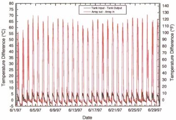
UFC 3-440-01
                                                                            14 June 2002

                                      FOREWORD

The Unified Facilities Criteria (UFC) system is prescribed by MIL-STD 3007 and
provides planning, design, construction, operations and maintenance criteria, and
applies to the Military Departs, the Defense Agencies, and the DoD Field Activities in
accordance with USD (AT&L) Memorandum dated 29 May 2002. UFC will be used for
all DoD projects and work for other customers where appropriate.

UFC are living documents and will be periodically reviewed, updated, and made
available to users as part of the Services’ responsibility for providing technical criteria
for military construction. Headquarters, U.S. Army Corps of Engineers (HQUSACE),
Naval Facilities Engineering Command (NAVFAC), and Air Force Civil Engineer
Support Agency (AFCESA) are responsible for administration of the UFC system.
Defense agencies should contact the preparing service for document interpretation and
improvements. Technical content of UFC is the responsibility of the cognizant DoD
working group. Recommended changes with supporting rationale should be sent to the
respective service proponent office by the following electronic form: Criteria Change
Request (CCR). The form is also accessible from the Internet sites listed below.

UFC are effective upon issuance and are distributed only in electronic media from the
following sources:

•   Unified Facilities Criteria (UFC) Index http://65.204.17.188/report/doc_ufc.html
•   USACE TECHINFO Internet site http://www.hnd.usace.army.mil/techinfo/index.htm.
•   NAVFAC Engineering Innovation and Criteria Office Internet site
    http://criteria.navfac.navy.mil/.
•   Construction Criteria Base (CCB) system maintained by the National Institute of
    Building Sciences at Internet site http://www.nibs.org/ccb.
Hard copies of UFC printed from electronic media should be checked against the
current electronic version prior to use to assure that they are current.

AUTHORIZED BY:

__________________________________             __________________________________
Dwight A. Beranek, P.E.                        Dr. James W. Wright, P.E.
Chief, Engineering and Construction Division   Chief Engineer and
U.S. Army Corps of Engineers                   Naval Facilities Engineering Command

__________________________________             __________________________________
Kathleen I. Ferguson, P.E.                     Frank Lane
The Deputy Civil Engineer                      Director of Analysis & Investment
DCS/Installations & Logistics                  Deputy Under Secretary of Defense
Department of the Air Force                       for Installations and Environment
                                               Department of Defense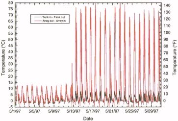
UFC 3-440-01
                                                                                             14 June 2002

                                           CONTENTS

                                                                                                          Page
INTRODUCTION
            1-1    PURPOSE AND SCOPE ........................................................... 1-1
Paragraph   1-2    APPLICABILITY. ....................................................................... 1-1
            1-3    REFERENCES ..........................................................................1-1
            1-4    ADDITIONAL RESOURCES .....................................................1-1
REQUIREMENTS
            2-1 INTRODUCTION. ...................................................................... 2-1
            2-2 ECONOMIC EVALUATION ....................................................... 2-1
Paragraph   2-2.1 Screening Tool. ...................................................................... 2-1
            2-2.2 Detailed Analysis and Study ................................................... 2-1
            2-3 FEASIBILITY DISCUSSION...................................................... 2-2
            2-3.1 System Selection. ................................................................... 2-2
            2-3.2 Summary. ...............................................................................2-2
            2.4 FUNDING ...................................................................................2-2
SYSTEM SELECTION, PLANNING, AND COORDINATION
            3-1 INTRODUCTION. ...................................................................... 3-1
            3-2 STANDARD SYSTEM TYPES. ................................................. 3-1
            3-2.1 Closed-Loop System .............................................................. 3-1
Paragraph
            3-2.2 Direct Circulation System ....................................................... 3-3
            3-3 SYSTEM SELECTION. ............................................................. 3-4
            3-4 SYSTEM LAYOUT .................................................................... 3-4
            3-4.1 Collector Sub-System ............................................................. 3-4
            3-4.2 Storage Sub-System............................................................. 3-10
            3-4.3 Transport Sub-System.......................................................... 3-11
            3-4.4 Control Sub-System.............................................................. 3-11
            3-5 COORDINATION..................................................................... 3-12
            3-5.1 Architect................................................................................ 3-12
            3-5.2 Structural Engineer ............................................................... 3-13
SYSTEM DESIGN
            4-1 INTRODUCTION. ...................................................................... 4-1
            4-2 COLLECTOR SUB-SYSTEM .................................................... 4-1
            4-2.1 Collector Specification ............................................................ 4-1
Paragraph   4-2.2 Collector Sub-System Piping and Layout ............................... 4-3
            4-3 STORAGE SUB-SYSTEM....................................................... 4-13
            4-3.1 Storage Tank Construction ................................................... 4-13
            4-3.2 Storage Tank Sizing ............................................................. 4-14
            4-3.3 Storage Sub-System Flow Rate ........................................... 4-14
            4-4 TRANSPORT SUB-SYSTEM .................................................. 4-15
            4-4.1 Transport Sub-System Design.............................................. 4-15
            4-4.2 Transport Sub-System Checklist .......................................... 4-21

                                                   i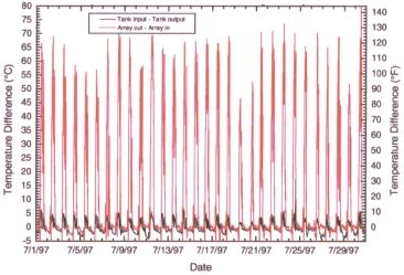
UFC 3-440-01
                                                                                                   14 June 2002

                    4-5 CONTROL SUB-SYSTEM....................................................... 4-22
                    4-5.1 Differential Temperature Control Unit (DTC) ........................ 4-22
                    4-5.2 Temperature Sensors and Locations ................................... 4-23
                    4-5.3 Monitoring Equipment...........................................................4-24
                    4-6 SAFETY FEATURES..............................................................4-25
                    4-6.1 Fall Protection .....................................................................4-25
                    4-6.2 Equipment Lockout and Disconnect ...................................4-25
                    4-7 CASE STUDY .........................................................................4-25

APPENDIX A REFERENCES .................................................................................. A-1

APPENDIX B HOT WATER LOAD ESTIMATIONS ................................................. B-1

APPENDIX C WATER QUALITY ANALYSIS........................................................... C-1

APPENDIX D EXAMPLE DESIGN CHECKLIST ...................................................... D-1

APPENDIX E EXAMPLE DRAWINGS CHECKLIST ................................................ E-1

APPENDIX F SOLAR ENERGY SYSTEM FUNDAMENTALS ..................................F-1

APPENDIX G SOLAR ENERGY CASE STUDY AT FORT HUACHUCA, AZ .......... G-1

                                                    FIGURES

Figure           Title

Figure 3-1. Closed-Loop Antifreeze System................................................................3-2
Figure 3-2. Direct Circulation System ..........................................................................3-3
Figure 3-3. System Selection Flowchart ......................................................................3-5
Figure 3-4. Flat-Plate Collector....................................................................................3-6
Figure 3-5. Minimum Collector Row Spacing ..............................................................3-8
Figure 3-6. Possible Array Configurations and Area .................................................3-10
Figure 4-1. Collector Manifold Types...........................................................................4-2
Figure 4-2. Collector Array Terminology......................................................................4-4
Figure 4-3. Reverse-Return Versus Direct- Return Piping Strategies .........................4-6
Figure 4-4. Steps in Developing a Reverse Return Piping Layout...............................4-7
Figure 4-5. Examples of Reverse-Return Piping .........................................................4-8
Figure 4-6. Manifold Sizing Example .........................................................................4-11
Figure 4-7. Manifold Sizing Example (Metric)............................................................4-12
Figure 4-8. Thermal Expansion Versus Temperature Differential for Copper Pipe ...4-14

                                                          ii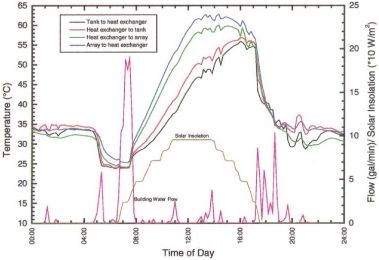
UFC 3-440-01
                                                                                                  14 June 2002

Figure 4-9. Calculation of Total Expansion Tank Volume .........................................4-19
Figure 4-10. Typical Pump and System Operation Curves ........................................4-22
Figure D-1. Manifold Sizing Worksheet ...................................................................... D-6
Figure F-1. Typical Solar Thermal Energy System......................................................F-1
Figure F-2. Typical Collector Efficiency Curve.............................................................F-6
Figure F-3. Typical Solar Collector Efficiency Plots.....................................................F-7
Figure F-4. Solar Fraction Versus Collector Area.......................................................F-13
Figure G-1. Photo of Collector Arrays ........................................................................ G-2
Figure G-2. Solar Hot Water System Piping Diagram ................................................ G-3
Figure G-3. Typical Array Layout................................................................................ G-4
Figure G-4. “Quad Rod” Double Wall Heat Exchanger .............................................. G-4
Figure G-5. Connection to the Existing Domestic System.......................................... G-5
Figure G-6. Equipment Housing ................................................................................. G-5
Figure G-7. Wiring Diagram........................................................................................ G-6
Figure G-8. Differential Temperature Controller ......................................................... G-6
Figure G-9. Solar Insolation Measured for May 1997................................................. G-9
Figure G-10. Solar Insolation Measured for June 1997............................................ G-10
Figure G-11. Solar Insolation Measured for July 1997 ............................................. G-10
Figure G-12. Hot Water Demand for May 1997........................................................ G-11
Figure G-13. Hot Water Demand for June 1997 ...................................................... G-11
Figure G-14. Hot Water Demand for July 1997 ........................................................ G-12
Figure G-15. Temperature Differences Across Heat Exchanger (May 1997) ........... G-12
Figure G-16. Temperature Differences Across Heat Exchanger (June 1997).......... G-13
Figure G-17. Temperature Differences Across Heat Exchanger (July 1997) ........... G-13
Figure G-18. Temperature Responses (8 May 1997)............................................... G-14
Figure G-19. Temperature Responses (17 June 1997)............................................ G-14
Figure G-20. Temperature Responses (15 July 1997) ............................................. G-15
Figure G-21. Supply and Return Temperature Differences (May 1997)................... G-15
Figure G-22. Supply and Return Temperature Differences (June 1997).................. G-16
Figure G-23. Supply and Return Temperature Differences (July 1997) ................... G-16
Figure G-24. Solar Array BTU’s Delivered and Hot Water Demand......................... G-17
Figure G-25. Solar Array Joule’s Delivered and Hot Water Demand ....................... G-17
Figure G-26. Solar Array BTU’s Delivered, Gas Usage and Hot Water Usage ........ G-18
Figure G-27. Solar Array Joule’s Delivered, Gas Usage and Hot Water Usage....... G-18

                                                     TABLES

Table        Title

4-1               Pressure Drop Corrections....................................................................4-10
B-1               Estimated Average Hot Water Loads for Various Facilities ................... B-1
C-1               Data for Calculating pH of Saturation (pHs) Calcium Carbonate ........... C-2
C-2               Prediction of Water Tendencies by the Ryznar Index ............................ C-2

                                                         iii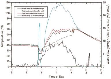
UFC 3-440-01
                                                                        14 June 2002

                                    CHAPTER 1

                                  INTRODUCTION

1-1    PURPOSE AND SCOPE. This manual provides guidance for the standard
design of active solar energy systems to preheat domestic and service water. The
systems treated by this manual are liquid based. Guidelines apply to the larger
commercial-scale applications that require an effort on the part of the designer, as
opposed to residential-sized "packaged" systems, which in the past have been
available from a number of manufacturers. The concepts developed in this document
are targeted for new construction, although most are also appropriate for retrofit
applications.

1-2   APPLICABILITY. This UFC applies to all service elements and contractors
developing active solar preheat systems.

1-3  REFERENCES. APPENDIX A contains a list of references used in this
document.

1-4     ADDITIONAL RESOURCES. For additional resources on solar water heating
applications, refer to the Whole Building Design Guide (WBDG) Internet site
http://www.wbdg.org/.

                                         1-1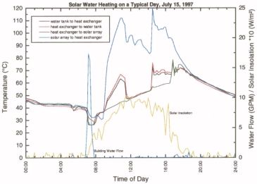
UFC 3-440-01
                                                                            14 June 2002

                                       CHAPTER 2

                                    REQUIREMENTS

2-1    INTRODUCTION. In view of a history of fluctuating energy costs and uncertain
availability of fossil fuels, the economic feasibility study of any energy-related project
becomes the foundation of the design process. For the case of renewable energy, Title
10 of the U.S. Code (10 USC) requires that an economic feasibility analysis be
performed for all new military construction to determine whether the use of renewable
forms of energy will result in a net monetary savings to the government. The
methodologies and parameters required for federal energy project feasibility studies are
mandated by federal law (10 CFR 436). Furthermore, installation of a renewable
energy system is required if it is deemed economically feasible. This chapter provides
the tools necessary to perform a feasibility study in accordance with these required
procedures.

2-2    ECONOMIC EVALUATION

2-2.1     Screening Tool. To evaluate the feasibility of designing and installing an
active solar preheat system, the first step will be to use the Solar Payback screening
tool developed by the Construction Engineering Research Laboratory (CERL). The tool
is a Microsoft Excel spreadsheet that contains screening criteria developed by the
National Renewable Energy Laboratory (NREL). The program is a quick,
straightforward tool that requires minimal input (general site location as well as starting
point energy costs and system costs) to calculate numerous payback periods for the
two most common solar hot water technologies (flat-plate and evacuated tube
collectors) when used to displace either electricity or natural gas energy costs. The tool
is available for download from http://www.cecer.army.mil/swp/swp.html.

2-2.2      Detailed Analysis and Study. If the results of the Solar Payback screening
tool indicate that an active solar hot water system should be considered further, then
the next step will be to perform a detailed life-cycle cost analysis (LCCA) to determine
the most effective design alternative to develop. LCCA calculations and reports will be
performed in accordance with a service’s economic analysis manual, such as TM 5-
802-1. Computer calculations will be performed using a service’s economic analysis
program, such as the Life Cycle Cost In Design (LCCID) computer program.
Information defined in this UFC document will be used in the development of the LCCA
calculations. For additional guidance in the development of the LCCA calculations,
refer to the American Society of Heating, Refrigerating, and Air-Conditioning Engineers
(ASHRAE) publication “Active Solar Heating Systems Design Manual”. The manual
was developed by ASHRAE, the Solar Energy Industries Association (SEIA), the
American Consulting Engineers Council (ACEC), and the Department of Energy (DOE)
contractors and is intended to give solar designers an effective means to use the
collective knowledge of government and industry to better select options for improving
the quality and energy efficiency of solar systems.

                                           2-1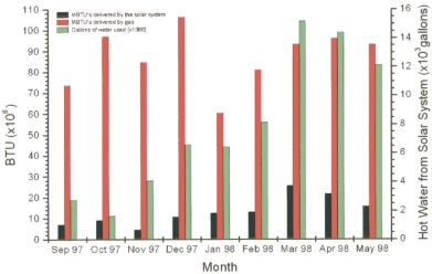
UFC 3-440-01
                                                                             14 June 2002

2-3    FEASIBILITY DISCUSSION

2-3.1     System Selection. If one or more systems show a positive LCC savings, the
system with the highest LCC savings must be designed. In the case of two systems
LCC savings having approximately equal values, the system with the highest savings-
to-investment ratio (SIR) should be chosen for detailed design. If no system shows a
positive LCC savings, an active solar energy system is not to be considered for the
project.

2-3.2    Summary. Examination of many feasibility studies shows that the service
water preheating application is typically the most cost-effective alternative. Space
heating by use of solar energy is best accomplished by passive solar building design.
Solar cooling of any form is seldom cost-effective, largely due to prohibitive equipment
and M&R costs.

2-4     FUNDING. One of the biggest obstacles to using solar hot water technologies is
often the inability to obtain the funding for the initial capital costs, even though a life-
cycle cost analysis might show that the investment would pay for itself several times
over. Funding for energy projects in general, and renewable energy projects in
particular, has been consistently reduced over the last several years. There are still
opportunities for funding these projects through the Department of Energy’s (DOE)
Federal Energy Management Program (FEMP), the US Army Engineering Center,
Huntsville’s Energy Savings Performance Contracting (ESPC) program, or the
Department of Defense’s (DOD) Model Utility Agreement. With the last two funding
mechanisms, a third party contractor or the local utility company provides the funding
for installing the solar hot water systems, and is paid back the investment through the
energy savings, over the term of the contract agreement.

                                            2-2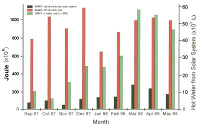
UFC 3-440-01
                                                                            14 June 2002

                                       CHAPTER 3

              SYSTEM SELECTION, PLANNING, AND COORDINATION

3-1    INTRODUCTION. This chapter provides criteria for selection of a specific type
and configuration of solar energy system, and discusses special issues that must be
considered. Once the system type is selected, coordination with the architect and
structural engineer is critical for determining estimates of roof area, roof and collector
support, and equipment space requirements. It should be noted that this manual
applies to the design of systems for the northern hemisphere. Appropriate corrections
should be made for the design of these systems in the southern hemisphere.

3-2     STANDARD SYSTEM TYPES. To meet the Services' goal of standardizing solar
energy installations, the following system types have been selected for use on all active
solar installations.

3-2.1     Closed-Loop System. The closed-loop solar energy system has proven to
be very reliable when designed and maintained properly, largely due to its ability to
successfully withstand freezing temperatures. Freeze protection is provided by
circulating a solution of propylene glycol and water through a closed collector loop.
Figure 3-1 is a schematic of the closed-loop system.

3-2.1.1    System Operation

3.2.1.1.1     Solar Loop. The differential temperature controller activates the solar
loop pump in the collector loop when the temperature difference between the collector
and storage is large enough for energy to be collected. The propylene glycol solution
circulates in a pressurized closed-loop through the solar collector to an external heat
exchanger. An expansion tank is provided to account for thermal expansion of the fluid
in the collector loop, stagnation, and over-pressure protection. Refer to APPENDIX F
for a discussion of stagnation conditions in solar systems.

3.2.1.1.2 Storage Loop. The control system activates the storage loop pump
simultaneously with the collector loop pump. Water in the storage loop is heated by the
solution in the heat exchanger and passed to the solar storage tank. When there is a
hot water demand, cold water is drawn into the solar storage (preheat) tank and solar
heated water is sent to an auxiliary water heater where it is heated further (if necessary)
and sent to the load.

3-2.1.2     Design Precautions. While the closed-loop solar energy system can
provide reliable service in any climate, certain design precautions must be taken.

                                            3-1
UFC 3-440-01
14 June 2002
Figure 3-1. Closed-Loop Antifreeze System
3.2.1.2.1 Collector Loop Check Valve. The check valve shown in the collector
loop is required to prevent "reverse thermosiphoning". This phenomenon can occur on
cold nights when the collector loop is not active. Warm solution from the lower part of
the loop (usually located indoors) becomes buoyant and rises toward the top of the loop
where it becomes colder. This cold, denser solution then drops to the bottom of the
loop, often passing through the heat exchanger and removing energy from the storage
loop. Extreme cases have resulted in frozen heat exchangers. Care should be taken to
locate the check valves so that the fluid in the collector loop can be drained if
necessary.
3.2.1.2.2 Piping and Component Protection. Fluid problems and associated
corrosion and maintenance issues are a common cause of closed-loop system failure.
However, results from the testing of degraded, uninhibited propylene glycol indicate that
with proper design, a closed-loop system may run without fluid maintenance for up to
20 years. Designers should ensure that non-ferrous piping and components are used
whenever possible, that no air is allowed to be drawn into or contained within the
system, and that the expansion tank and pressure relief valves are correctly sized to
prevent loss of solution and opening of the collector loop in the event of high pressure
stagnation.
3.2.1.2.3 Collector Loop Air Vent. The manual air vent shown at the top of the
collector loop allows air that has been released from solution to be purged. Propylene
glycol has a strong affinity for air, and dissolved oxygen in solution can greatly impair
system performance by contributing to corrosion.
3.2.1.2.4 Mixing Valves. Mixing valves are typically used to provide a high
3-2UFC 3-440-01
14 June 2002
temperature limit to the load or to supply the load with a specific hot water temperature.
It is important to ensure that the cold-water leg between the mixing valve and the cold
water supply to the solar storage tank is not used for connection to any other fixture.
Experience has shown that backflow through the storage tank can occur which sends
solar heated water to a cold water user. Although a check valve can be used in the
cold water supply to prohibit back flow, it is best to avoid this situation whenever
possible.
3-2.2 Direct Circulation System. The direct circulation system is the most basic
active solar energy system recommended for adoption by the Services. It should be
limited to use in locations where there are no freezing days, and where the water supply
is of sufficiently high quality (i.e., not highly scaling). The entire system operates at
existing water supply pressure and circulates potable water through the collectors
directly to storage. Figure 3-2 is a schematic of a direct circulation system.
Figure 3-2. Direct Circulation System
3-2.2.1 System Operation
3.2.2.1.1 Collector Loop. The collector loop pump is activated when the collector
temperature is large enough for energy to be collected and transferred to the solar
storage tank.
3.2.2.1.2 Storage Loop. The solar storage tank is used as a preheater for a
conventional water-heating unit, which is placed in series between the solar storage
tank and the load. When a demand for hot water occurs, cold water is drawn into the
3-3UFC 3-440-01
14 June 2002
solar storage tank where it then passes through the collector array (if activated) or on to
the conventional water heater.
3-2.2.2 Water Supply. Due to their inability to withstand freezing temperatures,
there is a relatively small market for direct circulation systems within the military.
However, because of their simplicity and straightforward operation, they have proven
superior when used at the proper location. An overwhelming consideration for the
success of these systems is the quality of the local water supply. Water is circulated
directly through the collectors, so that corrosion and scale buildup can be a major cause
of failure in these systems. In many regions where the water supply is of poor quality, it
is necessary to treat the incoming water supply so that it is within the prescribed quality
limits.
3-3 SYSTEM SELECTION. The standard systems described represent proven
designs that are both simple and reliable. System selection is largely based on the site
location, with the number of freezing days being the critical factor. Also important are
the estimated load size and the water quality at the site. Use APPENDIX B to estimate
average hot water loads for various facilities. Use APPENDIX C to evaluate the water
quality for various locations and water sources. Figure 3-3 is a flowchart to facilitate the
system selection process. This figure allows only service water preheating applications
to be chosen.
3-4 SYSTEM LAYOUT. The system layout phase identifies the solar energy system
requirements that will impose certain constraints on the building design. The architect
and structural engineer must be notified of these requirements early in the design stage
of the project. These requirements include proper orientation of the building,
identification of available roof area and structural criteria, and proper design and
location of the equipment room. Once these requirements are met and the necessary
building parameters are fixed, the solar system design can be completed.
3-4.1 Collector Sub-System
3-4.1.1 Representative Solar Collectors. Many flat-plate solar collector (refer to
2
Figure 3-4) sizes are available. Typical collectors range in size from about 16 to 47 ft
2
(1.5 to 4.4 m ) of net aperture area, with corresponding gross dimensions of 3 by 6 ft
(914 by 1829 mm), to 4 by 13 ft (1219 by 3962 mm). Two standard sizes are
2 2
considered to be about 30 and 40 ft (2.8 and 3.7 m ), with gross dimensions of 4 by 8
ft (1219 by 2348 mm) and 4 by 10 ft (1219 by 3048 mm), respectively. Single-glazed
collectors filled with liquid weigh approximately 4 to 5 lbs/ ft2 (192 to 239 Pa).
Recommended flow rates vary over a wide range, but most fall between 0.01 to 0.05
gals/min-ft2 (0.007 to 0.034 L/sec-m2).
3-4UFC 3-440-01
14 June 2002
Figure 3-3. System Selection Flowchart
Figure 3-3 Notes: Notes keyed into the flowchart are listed below by corresponding number.
1. For small loads on the order of a residential-sized service water heating system, the design effort and expense can be
avoided by purchasing a pre-designed "packaged" system from a reliable manufacturer. These systems are sold in a variety of
configurations, including drainback and closed-loop.
2. The number of freezing days at the site should be determined, based on recorded historical data. To meet the "no
freezing day" criterion, there should be no evidence of freezing temperatures for a period approximately equal to the expected
lifetime of the system. Existing data shows that no location in the continental U.S. can meet this criterion. Historical weather
data can be obtained from the Air Force Engineering Weather Data web site (http://www.afccc.af.mil/) or from local National
Weather Bureau stations or from the Environmental Data Service, a branch of the U.S. Department of Commerce.
3. Water quality should be determined using APPENDIX C.
4. Systems larger than 3,000 ft2 (279 m2) will require very large piping (4-inch (100 mm) diameter or larger) and roof
area, and are not recommended. If this situation occurs, the designer should consider installing two separate systems.
Although this approach is somewhat more costly, it improves the ease of construction and allows solar energy to be collected
in the event of one system being down due to maintenance or repair. The decision to use separate system depends on
specific project parameters and is left to the designer
5. Both the Fahrenheit (F) and Celsius (C) based versions of heating degree days are presented (the Celsius based
number is in parentheses). Heating degree days are based on the mean annual number of degree days using a base of 65
degrees F (18 degrees C). Only 30 to 50 percent volume propylene glycol/water solutions can be used in closed-loop systems.
Locations requiring a closed-loop system that have less than 4,000 (2222) heating degree-days per year may use the 30
percent solution; those having more heating degree days should use a 50 percent solution. This heating day criteria is
provided as a suggested guideline only. It is up to the designer to take into account each location's particular climate and
freezing-day characteristics when determining whether a 30 or 50 percent solution should be used.
3-5UFC 3-440-01
14 June 2002
Figure 3-4. Flat-Plate Collector
3-4.1.2 Array Size. The first step in the system layout is to estimate collector array
size (the actual array size cannot be determined until a specific collector is chosen for
the detailed design).
3-4.1.3 Array Tilt Angle. The collector array tilt angle is defined to be the angle
between the collector and the horizontal, with 0 degrees being horizontal and 90
degrees being vertical. The proper tilt angle is a function of the time of year when the
load occurs. For annual loads, such as service and process water heating, the widely
accepted practice is to tilt the collectors to the value of the local latitude. If the load
tends to have a seasonal variation, the tilt can be varied to favor the season. Examples
include seasonal hot water requirements, space heating, and space cooling. If the
collectors are tilted to the latitude angle plus 10 degrees, the energy output will be more
evenly distributed over the entire year, although winter losses will tend to increase, due
to lower outdoor temperatures. Tilting the array to the latitude minus 10 degrees favors
summer energy output. It is not generally recommended to tilt the array any more than
3-6UFC 3-440-01
14 June 2002
plus or minus 10 degrees from the site latitude. It should be noted that as the tilt angle
increases, the minimum spacing between rows due to shading increases and larger
roof area is required.
3-4.1.4 Array Azimuth Angle. The array azimuth angle is defined to be the angle
between the projection of the normal to the surface on a horizontal plane and the local
meridian (north-south line). Zero degrees is defined as due south, a due west facing
array is defined as plus 90 degrees, and a due east facing array is defined as minus 90
degrees (in the northern hemisphere). The optimal orientation requires the azimuth
angle to be 0 degrees (due south) whenever possible, although deviations of plus or
minus 20 degrees off of due south have a minimal effect on flat-plate system
performance.
3-4.1.5 Collector Grouping. Internal-manifold collectors should be grouped into
banks ranging from four to seven collectors each, with each bank containing the same
number of collectors. Proper sizing of the collector banks is essential to maintaining
uniform flow throughout the collector array. The maximum number of collectors that
can be banked together is a function of the maximum flow rate allowed in the plumbing,
internal manifold and riser diameters, thermal expansion characteristics of the collector
piping and absorber plate assembly, and the recommended flow rate of the particular
collector chosen (usually given in gallons per minute (liters per second) per collector or
gallons per minute per square feet (liters per second per square meter) of collector
area). Thermal expansion problems are minimized by keeping the bank size less than
eight collectors.
3-4.1.6 Minimum Array Row Spacing. The minimum row spacing must be
calculated for multi-row arrays. A general routine for north-south spacing of collector
banks can be devised, based on a "no shading" criterion for a particular time of year.
The guidance presented assumes no shading of the array on the "worst" solar day of
the year (21 December, when the sun is lowest in the sky in the northern hemisphere)
for the designated time period of 10 a.m. to 2 p.m. solar time. Most large-scale military
solar systems are installed on low-slope flat roofs, and there are two possible cases to
consider. The first is for a flat roof with enough space to locate the collector array at
one elevation. The second case is for a flat roof with too little space for the collector
array. This requires the collector banks to be "stepped", that is, each succeeding row of
collectors must be elevated. This arrangement is necessary if the collector roof area
required is larger than that available or if roof area costs are more expensive than
elevated rack costs. The equations developed for minimum collector row spacing are
presented graphically in Figure 3-5.
3-7UFC 3-440-01
14 June 2002
Figure 3-5. Minimum Collector Row Spacing
3.4.1.6.1 Azimuth Orientations. The curves shown in Figure 3-5 are for collector
azimuth orientations of plus or minus 20 degrees. For the due south orientation (0
degrees), the deviation from these results is less than 10 percent. Use of Figure 3-5 for
due south orientations is thus slightly conservative. The effect of elevating the rear
collector row (larger C/L values) shows a marked decrease in the minimum spacing
(S/L). The flat roof, no elevation collector case is represented by the curves where C/L
= 0.
3.4.1.6.2 Roof Pitch. Collectors can also be mounted on pitched roofs. Often,
when a solar energy system is to be added to a building, the roof is pitched and
constructed such that the collectors could be mounted on the roof surface. This
practice does not necessarily impose unreasonable constraints in the roof design, since
there is some flexibility in the choice of collector tilt angle. If the roof cannot be pitched
to allow flush mounting of the collectors, or if the tilt angle must be fixed, then the
collectors can be raised at one end to give them the proper tilt. Figure 3-5 can be used
to determine the spacing by including the appropriate roof pitch with the height C.
3.4.1.6.3 Array Layouts and Estimated Roof Area Options. Collector array
layouts and estimated roof area requirements for the system can be determined by
using the estimated array size. For example, assume that 818 ft2 (76 m2) of collector
area is required for a project located at 40 degrees N latitude. The number of collectors
to install can be determined by dividing the calculated array area by the net aperture
area of the collector. If a 4 by 8 foot (1219 by 2438 mm) collector with 31 ft2 (2.9 m2) of
net aperture area is to be used, the calculation results in 26.4 collectors. Since 26
collectors cannot be divided evenly into banks of four, five, six, or seven, the designer
must deviate from the calculated value by rounding to the next highest possibility result
(i.e., 28 collectors). These units can be grouped into four banks of seven collectors or
3-8UFC 3-440-01
14 June 2002
seven banks of four collectors each. The length required for the collector banks is the
width of the collectors plus connective piping. It is conservative to estimate 6 inches
(152 mm) of connective piping between collectors, 3 ft (914 mm) between banks in the
lateral dimension, and 4 ft (1219 mm) around the banks for personnel clearance. The
bank widths are then estimated to be 31 ft (9449 mm) for the seven-collector bank and
17.5 ft (5334 mm) for the four-collector bank. The distance required between collector
rows can be found from Figure 3-5. For example, an 8 ft (2438 mm) collector at 40
degrees N latitude requires row spacing of about 2.5 times 8 ft (2438 mm), or 20 ft
(6096 mm). The array layout should be determined by keeping in mind that the piping
length should be minimized while geometric symmetry is maintained. This guidance
results in a tendency for the banks to contain as many collectors as possible, and for
the array layout to be rectangular in area with an even number of banks installed in
multiple rows. Therefore, the case of four banks with seven collectors each is the most
preferred. A number of roof area dimensions should be proposed so the architect has
some flexibility in determining the building orientation and dimensions. Figure 3-6
shows three possible collector array layouts for the 28-collector array. Similar
consideration can be given to the use of a 4 by 10 ft (1219 by 3048 mm) collector. The
result would be 21 collectors (possibly rounded to 24 or 20), 25 ft (7620 mm) row
spacing (if needed), and banks of seven, six, or five collectors respectively.
3-4.1.7 Array Support Structure. The support structure must transmit the various
loads incident upon the array to the building roof structure without overstressing it. The
design must meet all code requirements and should be coordinated with, or reviewed
by, a qualified structural engineer. At the system layout stage, the structural engineer
or architect should have an idea about the building and roof type before the support
structure is planned. Although steel has often been used for array structures, all
systems designed under this guidance will be made from aluminum, to avoid the cost of
applying and maintaining a protective finish. Although it is difficult to generalize,
experience has yielded some useful estimates about the weight and cost of large
collector support structures. As a rough guideline for rack-type structures, the weight of
the structure should be less than 5 lbs/ ft2 (239 Pa) of collector area. The cost of the
support structure typically represents less than 15 to 20 percent of the total solar
system cost. Any support structures falling outside of these guidelines could be
considered inefficient from a cost versus performance view. It is expected that the
support structure may be heavier and more costly in areas where design loads are
higher or where stepped collector rows are required. Further, stepped arrays require
elevated walkways for maintenance a personnel, which results in higher material and
design costs.
3-9UFC 3-440-01
14 June 2002
Figure 3-6. Possible Array Configurations and Area
3-4.2 Storage Sub-System
3-4.2.1 Storage Tank Size. At the system layout stage, the storage tank volume
and dimensions have a major impact on the design and location of the equipment room.
Selection or specification of the storage tank requires first determining the appropriate
volume of the tank. The widely accepted practice for service water heating applications
is to provide a storage tank volume of 1.5 to 2 gals per square foot (61.1 to 81.5 L per
square meter) of collector area. Storage systems larger than this do not significantly
increase the performance of the solar system, and the additional costs associated with
larger storage are not justified. Storage systems smaller than this size can decrease
system performance. The lower performance is due to relatively high storage
temperatures, resulting in lower solar collector efficiencies. Within these guidelines, the
exact size of the storage tank is not critical to system performance and should be based
upon available standard sizes. To provide proper stratification and to meet space
requirements, vertical storage tanks are preferred. As tank size increases, space
considerations and floor area become increasingly critical. When it becomes apparent
that a single vertical tank is not possible, a horizontal tank or a series of vertical tanks
will be necessary.
3-10UFC 3-440-01
14 June 2002
3-4.2.2 Storage Tank Location
3.4.2.2.1 Indoor Versus Outdoor. As with conventional energy systems, a solar
system requires an equipment room to contain the heat exchanger, pumps, control
system, and associated plumbing. If possible, the equipment room should be designed
to house the solar storage tank. For retrofit situations where existing space does not
permit the required tank volume, an outdoor location may be chosen. However, many
factors discourage the location of storage tanks outside the building, such as a higher
annual standby energy loss (in most climates) and adverse environmental effects on
the tank (including ultraviolet and moisture-based degradation). Solar storage tanks are
not to be located underground. Underground tanks have had numerous problems,
including leakage due to tank and ground shifting and thermal stresses; corrosion due
to the lack of cathodic protection; tanks surfacing due to buoyant forces while empty;
and difficulty in retrieving and repairing sensors and instruments.
3.4.2.2.2 Tank Support and Floor Loads. Reinforced concrete pads and footings
are often required to ensure that the weight of the tank does not endanger the structural
integrity of the building. The design load calculation should take into account the
estimated weight of the empty tank, the water to be stored in the tank, the insulation,
and the tank support structure. The design load for the footing is also dependent on
the type of tank support used.
3-4.2.3 Legionnaire’s Disease. If a direct circulating system is supplying water for
domestic use, ensure that water in the storage tank is heated to a minimum of 140
degrees F (60 degrees C) in order to avoid any potential source of Legionnaire’s
disease. For additional information on Legionnaire’s disease refer to
http://www.efdlant.navfac.navy.mil/criteria.
3-4.3 Transport Sub-System. To ensure that the transport sub-system is properly
accounted for in the building design, space must be provided in the equipment room for
the heat exchanger, expansion tank, pumps, and system plumbing, in addition to the
storage tank and control system. Pipe chases are also required between the
equipment room and the space on the roof where the system will be located.
3-4.4 Control Sub-System
3-4.4.1 Control Strategy. For the control strategy, the designer must specify
operating modes and freeze/over-temperature protection methods. It should be noted
that the control strategy presented for the standard closed-loop system is intended to
be simple, reliable, and built with off-the-shelf components.
3.4.4.1.1 Pump Activation. Using the differential temperature controller, the
collector and storage loop pumps should be energized whenever the difference
between the absorber plate and storage tank temperatures is greater than some high
setpoint differential temperature TH, typically 15 to 25 degrees F (8 to 14 degrees C).
The pumps should stay on until that temperature difference is less than some low
setpoint differential temperature TL, usually between 5 to 8 degrees F (3 to 4 degrees
3-11UFC 3-440-01
14 June 2002
C).
3.4.4.1.2 Freeze Protection. The propylene glycol mixture used in the closed-loop
system provides freeze protection. Direct circulation is used only in non-freezing
climates. Because the direct circulation system is more or less a special type of closed-
loop system, its control strategy is the same.
3.4.4.1.3 Over-Temperature Protection. Over-temperature protection of the
collector loop in the event of stagnation is provided through expansion tank sizing (refer
to Chapter 4). The pressure-temperature relief valve located on the storage tank
supplies over-temperature protection of the storage loop. If a direct circulating system
is supplying water for domestic use, it is required that users be protected against the
possibility of live steam being issued from taps or showerheads. This protection is
provided through the proper use of relief and mixing valves.
3.4.4.1.4 Auxiliary Pump Switches. The use of auxiliary high- and low-
temperature switches that will trip the pumps as a backup to the differential controller
are not recommended. These switches are as prone to failure as the controller, and
have been the cause of many solar system failures.
3-4.4.2 Location of Controls. Whenever possible, electronic displays and visual
pressure and temperature gauges should be panel-mounted together in the mechanical
room. Temperature sensors, which are located on the collector manifolds and on the
storage tank, should be easily accessible for calibration and servicing. A common
problem is sources of electromagnetic interference with the sensor wiring. This
problem can be avoided by making the sensor wiring path as short as possible and by
using conduit separate from AC power wiring. It may be desirable to include extra
conductors for future expansion or maintenance needs.
3-5 COORDINATION. The system designer is responsible for ensuring that all
essential information is provided to the architect and structural engineer, so that the
building plan can accommodate the solar system requirements.
3-5.1 Architect
3-5.1.1 Roof Requirements. The most important requirement for the architect, with
regard to the solar energy system, is to provide adequate unshaded roof area and
proper orientation for the system. Other architectural requirements for roof design
include providing roof penetrations near the array for collector supply and return lines;
designing the array support structure; allowing adequate access to the array for
maintenance; including access to the roof for personnel (and equipment); including
walkways around the array; and locating the collector array above or near an area that
can be used for pipe chases.
3-5.1.2 Equipment Room
3.5.1.2.1 Location. The equipment room for the solar energy system hardware will
3-12UFC 3-440-01
14 June 2002
be configured to allow easy access by operation and maintenance (O&M) personnel.
The designer will minimize piping distances, both to the array and to the load.
3.5.1.2.2 Design. Whenever possible, the solar system equipment room will house
solar storage tank, heat exchanger, expansion tank, pumps, control system, and related
plumbing. The backup heating system will also be located in the equipment room. The
room will be sized to allow O&M personnel to move about freely and replace equipment
as necessary. A floor drain will be provided near the storage tank relief valve. Control
panels will be installed in easily accessible areas and will be clearly visible.
3-5.2 Structural Engineer
3-5.2.1 Array Support System. The structural engineer (or project designer, if
qualified) is responsible for the design of the array support structure once the architect
has decided on a roof type. This step includes deciding if a flush roof-mounted or
elevated rack-type support will be used and the type of materials and finish to be
considered for the structure.
3-5.2.2 Roof Loading. The roof loads due to the array are point loads, and depend
on the collector array layout and the type of array support structure used. By knowing
the array layout (the width, length, and approximate spacing of the array) and the
proposed roof design and array support structure, the structural engineer and architect
can determine the best proposed roof support mechanism.
3-13UFC 3-440-01
14 June 2002
CHAPTER 4
SYSTEM DESIGN
4-1 INTRODUCTION. This chapter presents the information required to complete
the solar energy system design.
4-2 COLLECTOR SUB-SYSTEM
4-2.1 Collector Specification
4-2.1.1 Collector Construction
4.2.1.1.1 Absorber Construction and Components. The solar collector absorber
surface normally has two separate components: the absorber plate and fluid
passageways. Many types of absorber designs have been used, such as parallel or
serpentine tubes bonded to the absorber plate and double plates rolled together and
bonded with hydrostatically expanded fluid passages. The method for bonding the
tubes, the circuit flow path, and the absorber surface properties are each critically
important to collector performance. The flow path geometry, cross-sectional area, and
flow rate determine the fluid pressure drop across the collector. This pressure drop
affects the flow distribution throughout the array. Methods used to bond the flow tubes
to the absorber plate include mechanical bonds (soldered, brazed, or welded),
adhesives, and mechanical encirclement. Flow tubes that have separated from the
absorber plates are a leading cause of poor performance for flat-plate collectors. It is
imperative that the bond be able to withstand the expected stagnation temperature of
the collector and the daily temperature variations to which the collectors are exposed.
Serpentine flow tubes and roll-bonded absorber plates can trap the heat transfer fluid in
the collector, which can freeze and burst the tubes or absorber plate. Some roll-
bonded absorbers have also been found to separate with time and cause flow problems
or short-circuiting within the fluid passageway.
4.2.1.1.2 Absorber Surface. The absorber plate surface is also an important factor
in the performance of the collector. There are two basic surface finishes, selective and
non-selective. Selective surfaces are typically finished with black chrome or black
nickel deposited film. Non-selective surfaces are usually finished with flat black paint
and can have as large a value of emissivity as they do absorptivity. Selective surfaces
have the advantage of absorbing the same amount of energy as the painted surface,
but they emit much less radiation back to the cover. Non-selective painted surfaces
have had numerous problems with fading, peeling, and outgassing. In contrast,
deposited metallic surface coatings have an excellent history for retaining their
properties with time. The most common absorber plate materials are copper, although
aluminum absorbers can still be found. Copper has shown the best success due to the
lack of thermal expansion problems with the attached copper flow tubes.
4.2.1.1.3 Collector Manifold. The collector manifold is the piping that branches
4-1UFC 3-440-01
14 June 2002
from the array supply to each of the individual collectors. There are two main types of
collector manifolds: external and internal. External-manifold collectors have small
diameter inlets and outlets that are meant to carry the flow for only one collector. The
manifold piping to each inlet and from each outlet remains external to the collector.
Today, external-manifold collectors are being replaced by those with internal manifolds.
Internal-manifold collectors have larger manifolds designed to carry the flow for many
collectors connected together, with the manifolds built into the collector unit. Figure 4-1
shows an example of both types of manifold collectors. The internal-manifold collector
has many advantages, particularly when used in large systems. Benefits include
reduced costs for piping materials, pipe supports, insulation, and labor; more effective
flow balancing, which improves thermal performance; and the reduced heat losses to
ambient air. Use internally manifolded collectors for all new design projects (externally
manifolded collectors will not be used).
Figure 4-1. Collector Manifold Types
4.2.1.1.4 Collector Glazings. Collector covers, or glazings, are required to let
radiant energy from the sun through to the absorber and to prevent convection from the
hot absorber plate to the ambient air. Some properties to consider when choosing
glazings are structural integrity and strength, durability, performance and safety.
4-2UFC 3-440-01
14 June 2002
Tempered, low-iron glass is by far the most common glazing used because of its
excellent optical properties and durability. Clear plastics, such as acrylics and
polycarbonates, have a history of problems with clarity over time due to ultraviolet
degradation and are not recommended. Double-glazing reduces the thermal losses
from the collector, but also decreases optical efficiency and increases weight and cost.
This fact can be seen on a collector efficiency plot as a decrease in the FR value and a
decrease in the slope FRUL. (Refer to APPENDIX F for additional discussion.) For
certain higher temperature applications, the increase in efficiency at larger values of (Ti-
Ta)/I may warrant the extra expense of double glazing, but for service water heating
applications, single-glaze collectors will suffice.
4.2.1.1.5 Insulation. An insulating material is required behind the absorber plate
and on the sides of the collector to reduce conduction losses. Insulation types currently
in use include fibrous glass, mineral insulation, and insulating foams. The primary
considerations of the insulating materials are their thermal conductivity, ability to
withstand stagnation temperatures and moisture, dimensional stability, flammability,
and outgassing characteristics. Fibrous glass, closed cell polyisocyanurate foam, and
polyurethane foams are currently used in most solar systems. Polyurethane foam is
especially well suited because of its ability to retain its shape and to resist moisture that
may be present from condensation. Often, a layer of fibrous glass will be sandwiched
between polyisocyanurate insulation and the absorber plate, since this material is better
suited to withstand the high stagnation temperatures, which can exceed 350 degrees F
(177 degrees C) in that part of the collector.
4-2.1.2 Collector Selection. Required information on the chosen collector includes
the net aperture area (Ac); overall dimensions of length or height (L) and width (W); the
manufacturer's recommended collector flow rates (CFR) and the pressure drop across
the collector at that flow rate; the internal manifold tube diameter; and the collector
weight when filled. The designer should note whether the manufacturer recommends a
maximum number of collectors per bank less than seven. Of special importance are
2
the values for Ac and CFR. While collector areas range from approximately 16 to 47 ft
(1.5 to 4.4 m2), it is recommended that collectors with net areas of 28 ft2 (2.6 m2) or
more be specified whenever possible. For large commercially-sized arrays, smaller
collectors result in higher installation costs due to increased materials and labor
required to achieve a given array area. The pressure drop is often reported in units of
"ft of water". The following range of values could apply to typical flat-plate collectors: Ac
= 28 to 40 ft2 (2.6 to 3.7 m2), Length = 8 to 10 ft (2438 to 3048 mm), Width = 4 to 5 ft
2 2
(1219 to 1524 mm), CFR = 0.01 to 0.05 gals/min-ft (0.007 to 0.034 L/sec-m ), pressure
drop = 0.1 to 0.5 psi (690 to 3447 Pa), internal manifold diameter = 1 to 1.5 inches (25
to 38 mm), and collector filled weight = 100 to 160 lbs (45 to 73 kg). When the designer
has this information, the final array layout can be completed.
4-2.2 Collector Sub-System Piping and Layout
4-2.2.1 Layout and Terminology. Figure 4-2 provides an example of a collector
array layout with the appropriate terminology.
4-3UFC 3-440-01
14 June 2002
Figure 4-2. Collector Array Terminology
4.2.2.1.1 Collector Array. The collector is one internal-manifold, flat-plate collector
unit. The collector array is the entire set of collectors necessary to satisfy the collector
area specified by the thermal analysis. These collectors are often connected together
into smaller sub-arrays, or banks. These banks can be arranged in different ways (rows
and columns) to provide the required area, allowing the roof shape to vary depending
on the building plan. "Supply" piping provides unheated fluid to the array and "return"
piping carries heated fluid away from the array.
4.2.2.1.2 Manifolds. The piping used to carry the heat transfer fluid through the
array can act as either manifold (also called header) piping or riser piping. Simply
stated, the pipes that act as risers branch off of a main supply pipe, or manifold.
Manifold piping typically serves two functions, as an array manifold (supply or return) or
as a bank manifold (supply or return). As the name implies, the array supply manifold
is the supply for the entire array, whereas a bank supply manifold is the pipe run
consisting of all of the collector internal manifolds, after the bank is connected together.
The bank manifold acts as a riser off of the array manifold. For the case of a small
system that has only one bank, the array supply manifold is the same as the bank
manifold. When more than one bank exists, the array supply manifold branches to
4-4You can also read