Optical grinder: sorting of trapped particles by orbital angular momentum
←
→
Page content transcription
If your browser does not render page correctly, please read the page content below
Research Article                                        Vol. 29, No. 9 / 26 April 2021 / Optics Express 12967

Optical grinder: sorting of trapped particles by
orbital angular momentum
VALERIIA B OBKOVA , * J AN S TEGEMANN , R AMON D ROOP, E ILEEN
O TTE , AND C ORNELIA D ENZ
Institute of Applied Physics, University of Muenster, Corrensstr. 2/4, D- 48149 Muenster, Germany
* bobkova@uni-muenster.de

Abstract: We customize a transversely structured, tunable light landscape on the basis of orbital
angular momentum (OAM)-carrying beams for the purpose of advanced optical manipulation.
Combining Laguerre-Gaussian (LG) modes with helical phase fronts of opposite OAM handedness,
counter-rotating transfer of OAM is enabled in a concentric intensity structure, creating a dynamic
"grinding" scenario on dielectric microparticles. We demonstrate the ability to trap and rotate
silica spheres of various sizes and exploit the light fields’ feature to spatially separate trapped
objects by their size. We show the adaptability of the light field depending on the chosen LG
mode indices, allowing on-demand tuning of the trapping potential and sorting criteria. The
versatility of our approach for biomedical application is examined by spatial discriminating yeast
cells and silica spheres of distinct diameter.

Published by The Optical Society under the terms of the Creative Commons Attribution 4.0 License. Further
distribution of this work must maintain attribution to the author(s) and the published article’s title, journal
citation, and DOI.

1.   Introduction
More than 50 years ago Arthur Ashkin first observed acceleration and trapping of dielectric
particles caused by radiation pressure of two counter-propagating laser beams, paving the way to
the single-beam gradient trap – today known as optical tweezers [1]. Nowadays optical tweezers
cover a bright field of applications in various branches of natural sciences, namely biology [2],
microrheology [3], force measurement techniques [4], and others. Employing optical methods
for aforementioned purposes has the advantage of natural access to the size scales, comparable
to the light wavelength. For instance, optical means enable size-selective micro- and even
nano-manipulation [5–8], such as separation of particles and cells, which is of major significance
for biological and medical diagnostic procedures [9].
   The most straightforward way of optical-tweezers-based separation of objects is the individual
spatial manipulation of respective objects by a single-beam tweezers. In this case, each object is
trapped and moved separately, representing a time-consuming procedure. If sorting is desired,
additional discrimination of the objects by eye or detection algorithms are required as it is
realized, for example, in flow cytometry [10]. Advancing optical manipulation beyond this
simple approach enables simultaneous handling and, in particular, sorting of multiple micro- and
nano-objects at a time. This can be obtained either in a static way by diffractive optical elements
[11] or in a dynamic way by computer-generated holograms [12], what grants simultaneous
access to a high number of independent, discrete optical traps. For instance, holographic lenses
and gratings can be shaped by a phase-only liquid crystal spatial light modulator (SLM) [13] in
the conjugated trapping plane, allowing the formation of multiple discrete and independent single
traps within the trapping volume [12]. By digitally tuning these computer-generated holograms,
the position of the light focus and, thus, the trapped object, can be spatially and temporally
adapted. This dynamic, three-dimensional manipulation in space by holographic optical tweezers
(HOT) opened new opportunities for particle sorting processes [5,14].

#419876                                                                    https://doi.org/10.1364/OE.419876
Journal © 2021       Received 22 Jan 2021; revised 11 Mar 2021; accepted 11 Mar 2021; published 13 Apr 2021
Research Article                                                              Vol. 29, No. 9 / 26 April 2021 / Optics Express 12968

   Though single or multiple spot HOT allows to transport particles on predefined trajectories in
space, the introduction of spatially structured light [15] into optical manipulation has opened a
number of versatile approaches to general optical trapping. For instance, continuous amplitude
and phase distributions allow handling multiple particles at once in a single, but complex
light structure [16]. Furthermore, phase structured light can reveal another additional feature
for advance manipulation: orbital angular momentum (OAM), transferable to trapped objects
[17–19]. OAM-carrying light fields include a helical phase front structure and, consequently, a
phase singularity in the center. This phase structure is described by exp(ilφ) (φ: polar angle) and
is, among others, embedded in helical Laguerre-Gaussian (LG) modes. In this case, each photon
carries an OAM of lℏ per photon in addition to its linear momentum (radiation pressure). Here,
l ∈ Z is the topological charge, which characterizes the azimuthal (transverse) change of phase in
the helical structure. If a light landscape embeds a phase gradient, trapped objects move along
the intensity structure in the direction of increasing phase [20]. Light-matter interactions induced
by the transfer of OAM were intensively investigated within the last decades both theoretically
[21,22] and experimentally and find applications in such fields as metrology [23], microparticles
chirality [24], microbiology [25], and many more [26]. A review on the role of OAM for optical
trapping can be found in [27].
   Due to its customizable properties, structured light fields are nowadays a key tool for advanced
optical trapping and manipulation [28]. However, these light fields bear the not yet fully exploited
potential of automized particle sorting by establishing a connection between discrimination
criterion and the inscribed light field properties. Since OAM enables particle movement per
se within a complex light field without the need of adapting the respective field, the further
customization of OAM by adapting the topological charge and multiplexing OAM-bearing beams
by HOT may pave the way to innovative trapping potentials, allowing optical manipulation,
including self-driven sorting. In our approach, we exploit this potential of structured light and
design a sophisticated light field configuration based on the combination of helical LG modes of
counter-rotating OAM in a joint trapping volume. By our approach, we enable autonomously
sorting of particles by size in a single continuous light landscape, revealing a connection between
LG mode indices and particle diameter. Further, we demonstrate the customization of our
proposed method for biological applications by trapping and sorting living yeast cells from silica
microspheres.

2.   Customization of light for realizing an OAM-based optical grinder
For the design of a continuous OAM-bearing trapping potential, imparting the self-driven sorting
feature by particle size, we transfer the principle of a mechanical grinder mill into optics: to
obtain an optical, dynamic "milling" scenario we combine two LG beams of different radii
and opposite OAM in a joint trapping landscape. From the variety of OAM-carrying beams,
we choose LG modes for the realization of the optical grinder although other beams can also
be considered. The self-similarity of LG modes after Fourier transformation is an attractive
advantage for their implementation of a concentric double ring structure in HOT.
   The light field distribution of a LG beam in polar coordinates (ρ, ϕ, z) is then given by [22]
                                                            )︃ l
                                               √      ρ                          ρ2
                                          (︃                             (︃           )︃
          E   LG
                   (ρ, ϕ, z) = E (ρ, z)
                                G
                                                   2               Lpl        2          exp (−i(2p + l)ξ(z)) exp(ilϕ),              (1)
                                                     ω(z)                       ω(z)2

where EG (ρ, z) is a paraxial representation  )︂of a Gaussian beam, ω(z) is the radius of the beam at
                                          ρ2
                                       (︂
distance z from the beam waist, Lp 2 ω(z)2 is the LG polynomial, ξ is the Gouy phase. Integer
                                     l

mode indices l and p determine the spatial distribution of the LG beam: p is the number of nodes
along the radial direction and l is the topological charge being related to the beam’s helical phase
front, described by the term exp(ilϕ). For the realization of the proposed geometry, we choose
Research Article                                     Vol. 29, No. 9 / 26 April 2021 / Optics Express 12969

two LG beams that show only a single annulus of intensity each, i.e. p = 0 for both beams. The
resulting concentric intensity rings have different radii and carry OAM of opposite handedness
to enhance the sorting process. An illustrative example of such a light field distribution with
topological charges (l1 = −2 and l2 = 11) is shown in Fig. 1(a). In general, the chosen light
landscape and its features are customizable by the choice of topological charges l1,2 , which
determines the radii r1,2 per embedded LG beam.√︁From Eq. (1) radius of a LG mode with
p = 0 depends on the topological charge as rl = ω l/2 [29]. Thus, the choice of topological
charge values for each LG mode is the key for the realization of the named potential landscape
properties. For the experimental realisation of a "grinding" scenario, we choose high values of
the topological charges in the range of l = 40 to l = 110 resulting in a strong value of OAM per
photon in each LG beam.

       Fig. 1. (a) Example of an optical grinding unit, which consists of two counter-rotating
       LG beams with p = 0 and l1 = 2 and l2 = −11 and r1,2 (l1,2 ) respectively (simulation). (b)
       Sketch of the experimental holographic optical trapping system in an inverted microscope.
       L: lens, SLM: spatial light modulator, FF: Fourier filtering, QWP: quarter wave plate, DM:
       dichroic mirror, MO: microscope objective, IS: white light illumination system

   Note that, if an independent adaption of annulus radius and topological charge is desired,
perfect optical vortex beams [30] could be implemented. However, for close located intensity
rings, this approach leads to an undesirable strong intensity modulation, that might affect trapping
stiffness.
   For experimental implementation of the optical trapping light fields we use a holographic beam
shaping approach based on a phase-only SLM [31]. Figure 1(b) illustrates the basic concept of
the setup. A collimated laser beam with a transverse Gaussian intensity distribution is structured
in amplitude and phase by a pure phase mask displayed on the reflective SLM. Amplitude
modulation is achieved by implementing a weighted blazed grating approach [32]. We filter
the first diffraction order, carrying the encoded amplitude and phase information, within a 4f
imaging system. After that, the spatially tailored light is focused by the high numerical aperture
microscope objective into the trapping plane. To observe the sample, we use the white light
illumination of the microscope, while visualization of the light fields is facilitated by replacing
the sample by a mirror.
   The intensity and phase of an exemplary, experimentally realized light field, which was
afterwards employed for sorting, its theoretical counterpart, as well as the according information
encoded on the SLM are illustrated in Fig. 2. We design the SLM hologram aiming to get
a trapping landscape of two close located intensity rings with high topological charges and
adjustable "gap" between them. Since Fourier transformed coherent superposition of the two
LG modes does not obtain continuous radial phase gradient structure, we spatially separate
the two LG modes on the SLM hologram by a circular cut, similar to the method described in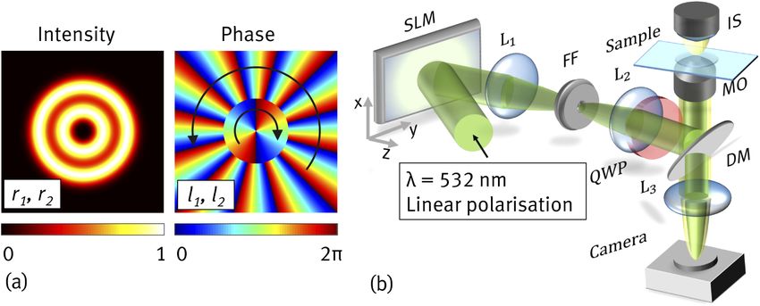
Research Article                                     Vol. 29, No. 9 / 26 April 2021 / Optics Express 12970

[33]. Intensity and phase distributions of the tailored light field are shown in Fig. 2 (a) and (b)
respectively. This approach results in a trapping landscape, consisting of two intensity rings.
Each of these rings obtains a high intensity gradient, which is important feature for optical
trapping and will be described in details in the following subsection. The outer ring obtains an
additional intensity modulation (see Fig. 2 (c) and (e)), which is caused by interference on the
phase jumps on the circular edge, splitting phase structures of two LG modes. This behavior was
investigated in more details in [33]. However, note that, due to presence of the strong continuous
phase gradient in the outer ring (see Fig. 2 (d) and (f)), the desired optical trapping and guiding
behavior within this ring is not significantly affected [20]. The presented experimental phase
distribution was obtained from the transverse intensity pattern formed by off-axis interference of
the tailored light field and a reference beam (plane wave) of the same polarization [34].

        Fig. 2. Spatial distributions of intensity, x-cut along the white dashed line, and phase ad-
        dressed to the SLM (a,b), numerically simulated in the sample plane (c,d) and experimentally
        measured (e,f) for LG beams with p1,2 = 0 , l1 = 40 and l2 = −70.

3.     Experimental sorting by the optical grinder
3.1.    Particle manipulation and size-selective criteria
In our experiment (Section 3.2), we use silica microspheres suspended in water as probes to be
trapped within our light landscape. We investigate the motion of silica particles (1 µm to 1.5
µm diameter) and, subsequently, yeast cells (3 to 5 µm diameter) in a light field of wavelength λ
= 532 nm. The motion of particles in a light landscape is influenced by the radiation pressure
of light and can be described in terms of linear and angular momentum transfer to a particle
[35]. Two forces originate from linear momentum transfer from light to a particle: scattering
force, co-directed with the energy flux and proportional to the light intensity, and gradient force,
proportional to the gradient of the light intensity. The gradient force drags particles (refractive
index nparticle > nmedium ) to regions of highest intensity. Dielectric particles are optically trapped
Research Article Vol. 29, No. 9 / 26 April 2021 / Optics Express 12971
in an equilibrium position of before mentioned forces. To enable the equilibrium, tight focusing
(i.e. high-NA) of the trapping beam is necessary, so that gradient forces can balance strong
scattering forces. In the case of our optical grinder, this means, particles can be trapped in the
local maxima of a focused LG intensity ring. Note that the z-position of the trapping plane within
the sample volume varies depending on the parameters of the beam (details see below) [21].
Additionally, the optical fields of helical phase front transfer OAM to a trapped particle, inducing
orbiting along a defined ring trajectory. Here, a torque of lℏ per photon is transferred to a silica
sphere interacting with a LG beam, inducing its orbiting along the intensity ring structure.
We need to consider that, for the optical grinder, the simultaneous influence of both LG modes
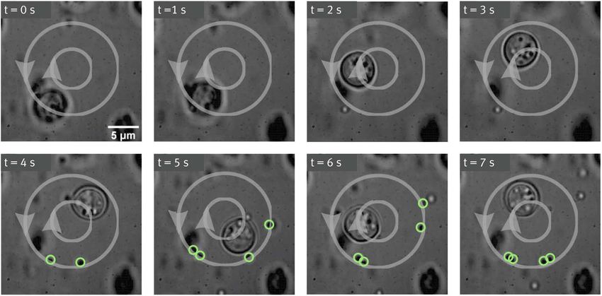
onto trapped particles has to be taken into account. Figure 3(a) shows a graphical representation
of how forces will act on particles of different sizes, trapped in the outer intensity ring. We
present a transverse cut of the intensity landscape (black dashed line) and the respective intensity
gradient profile (blue solid line). A grey area highlights the spatial range in which gradient forces
are acting onto an exemplary particles of two various sizes. Both spheres are initially trapped
in the outer intensity ring; particles are centered at the intensity maximum where the intensity
gradient is zero. Taking the spatial extent of particles into account, the graph reveals that smaller
1 µm particles (shown on the right side) only experiences gradient forces originating from the
outer ring. In contrast, a larger 1.5 µm sphere (shown on the left side) experiences gradient
force from the inner intensity ring in addition to the ones from the outer ring due to its larger
size. Since the intensity of the inner ring is higher and the gradient stronger than the one of the
outer ring, the particle will be pulled into the inner ring. By adjusting the distance d of the two
rings’ intensity peaks, we are able to select particles of which size will experience forces of only
one or both rings and, therefore, will be trapped in the outer or inner ring, respectively. This
size-selective property is a key feature for the grinder’s particle sorting process.
Fig. 3. (a) The following profiles are shown on the graph: intensity cut of the light
trapping landscape (black dashed line), gradient of intensity ∇I (blue solid line), and the
range of gradient forces, acting to a particle, depending on its size (gray area with red
borders). (b) Timelapse of the particle movement in the optical trap and their discrimination
according to the size. Trapped transparent dielectric silica spheres have the sizes of 1 and
1.5 µm (diameter). The exemplary trajectories of two 1.5 µm particles are shown in colour.
Topological charge of the inner ring is chosen to be l1 = 40, for the outer ring l2 = −70,
giving a distance d between the maxima of the rings of 1.3 µm.
Moreover, it was shown that, for LG beams, the z-position of the trapping plane in relation
to the beam waist plane depends on the sphere size and the parameters of the beam, namely its
topological charge [21]. Specifically, the smaller the topological charge value, the further is
the beam waist from the equilibrium trapping plane for a fixed particle size. Thus, the particle
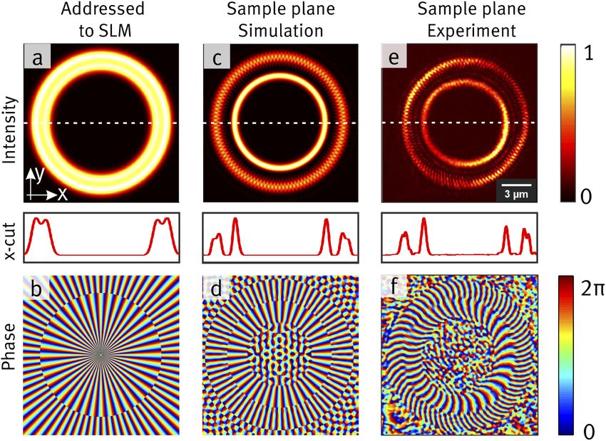
once being trapped in the inner ring of lower topological charge cannot escape to the outer ring,Research Article Vol. 29, No. 9 / 26 April 2021 / Optics Express 12972 located closer to the beam waist plane, due to the scattering force being co-directed with the beam propagation. Hence, once the bigger particles perform the transition to the inner ring, they keep orbiting there without disturbance. 3.2. Size-selective particle sorting For the experimental demonstration of size-selective particle sorting by our tailored light landscape, we choose dielectric silica particles of 1 µm and 1.5 µm diameter, suspended in water. To discriminate between sizes, lager, i.e., 1.5 µm particles shall move to the inner ring, whereas smaller, i.e., 1 µm particles shall be trapped in the outer ring. For this purpose, we set the parameters of the grinder’s LG modes to l1 = 40 and l2 = −70 (cf. Section 2., Fig. 2 (e) and (f)), such that the transverse distance of the intensity maxima of the rings in the trapping volume is given by d = 1.3 µm. To avoid azimuthal intensity asymmetry after focusing [36] within the experimental holographic trapping setup (Fig. 1(b)), the polarization of the beam is set circular using a quarter wave plate (QWP) before entering the high-NA microscope objective (MO). The beam is focused by a 100x, 1.4 NA oil immersion MO creating the tailored light field within the solution of silica microparticles in water. After around 3 seconds we observe all bigger particles being concentrated in the inner ring of the trap. Figure 3(b) shows an exemplary time lapse of this observation. Trajectories of two 1.5 µm silica spheres are shown in red and blue for better visibility. The time lapse clearly reveals the customized sorting behavior of our grinder as outlined in Sec.3.1. Visualization 1 additionally demonstrates the described sorting action. 3.3. Discriminating yeast cells from silica spheres in the optical grinder To demonstrate the potential of our sorting method for biological applications as well as its adaptability for various object sizes, we examine the optical grinding scenario employing yeast cells and 1 µm silica spheres mixed in water. To collect yeast cells in the inner ring, whereas the silica beads orbit in the outer ring, we adjust the distance d between the rings’ intensity peaks by changing topological charges of the LG modes. Since the mean yeast cell diameter is approximately 5 µm, we increase d up to 4.8 µm by setting l1 = 40 and l2 = −110. The time lapse in Fig. 4 shows that sorting takes again place within 3 seconds such that the yeast cell orbits in the inner ring, whereas 1 µm silica spheres are trapped in the outer intensity ring. This scenario clearly visualizes our methods’ adaptability and potential for future applications, which we also discuss in the following section. 3.4. Discussion To evaluate the presented results with respect to the implementation of the described method for the analysis of objects’ size deviation, we focus on some particular experimental cases. For instance, the initial location of particles of different sizes relative to the geometry of "optical grinder" is crucial for the results analysis. When the trap is first activated, due to their primary location, some of the particles smaller than the critical radius might be trapped in the inner ring, even though based on the chosen discrimination parameters only larger particles shall be located there. Hence, the initial distribution of particles in the trap should be taken into account when carefully interpreting the results on the qualitative analysis of size variation. Furthermore, a suspension might consist of more than two particle sizes or the scales are not predefined. In this case, we can take the advantage of the HOT setup to dynamically adjust the light landscape and thereby the discrimination parameter. Only particles with the radius bigger than a critical one would be dragged into the inner ring, such that the dynamic tuning of the light landscape can be used to estimate the particle size distribution in the sample. For solutions of particles with more than two different sizes, we could even implement additional discrimination rules by including multiple concentric rings with a predefined distance between them. In this case, particles will
Research Article                                       Vol. 29, No. 9 / 26 April 2021 / Optics Express 12973

       Fig. 4. Time lapse shows discrimination of yeast cells (approx. 5 µm diameter) from 1
       µm silica spheres in the tailored light landscape, specifically adapted for this purpose. The
       topological charge is chosen to be l1 = 40 and l2 = −110 for the inner and the outer ring
       respectively. The resulting distance between two rings is 4.8 µm. For the better visibility,
       silica microparticles are marked with green rings.

assemble in different rings depending on their radius. These examples highlight the adaptability
of the proposed method, which will also be beneficial for biological applications.
   A standard biological sorting process is typically realized in two steps: first, cells discriminating
from each other based on predefined criteria and, subsequently, spatial splitting into two or more
groups. The proposed "grinding" scenario discriminates the cells by their size and spatially trap
them within a single process. Further, as presented by the introduced setup (Fig. 1(b)), sorting by
the optical grinder is realized in the sample plane of an inverted microscope. Thus, the rapidly
evolving microscopy and microfluidics methods, often based on this kind of microscopes, can
easily be complemented by our sorting technique. Our technique allows obtaining the qualitative
analysis of the objects’ size deviation within the sample solution. Further development would be
required to additionally provide reservoir separation of various sized objects, however, compared
to existing cytometry-based cells sorting methods [37] we highlight the following advantages of
the proposed technique: First, the preparation of the sample is very simple, namely, no prelabeling
of the cells is required and if initially the solution is kept in a chamber with thin glass walls,
no segregation of it into a specific device is needed, what significantly simplifies the operation.
Second, the proposed method enables investigation of solutions with a very limited volume or
samples with toxic fluids. Additionally, the adjustment of discrimination parameter in a HOT
setup facilitates the dynamic analysis of the sample solution.

4.   Conclusion
In this paper we combine well-known OAM carrying LG beams in a versatile complex 3D
light landscape – the optical grinder – such that it allows not only optical trapping but also
self-driven size-dependent particle sorting. We employ closely neighbored concentric intensity
structures with opposite handedness of OAM, enabling a dynamic "grinding" scenario. Using
a phase-only SLM for shaping the according light field, we are able to dynamically adapt the
LG beam parameters by which we simultaneously set the size limit for particles to be trapped
in the inner and the outer ring. Finally, we spatially separate yeast cells from silica spheres
by adopting the trap parameters. By this proof-of-principle experiment we demonstrate our
Research Article Vol. 29, No. 9 / 26 April 2021 / Optics Express 12974
method’s capabilities and give insights into its future potential for size discriminating tasks in
medicine or microbiology.
Funding. Horizon 2020 Framework Programme (ColOpt ITN 721465); Deutsche Forschungsgemeinschaft (DE
486/23-1).
Disclosures. The authors declare no conflicts of interest.
Data availability. Data underlying the results presented in this paper are not publicly available at this time but may
be obtained from the authors upon reasonable request.
References
1. A. Ashkin, “Acceleration and trapping of particles by radiation pressure,” Phys. Rev. Lett. 24(4), 156–159 (1970).
2. A. Ashkin, “History of optical trapping and manipulation of small-neutral particle, atoms, and molecules,” IEEE J.
Sel. Top. Quantum Electron. 6(6), 841–856 (2000).
3. D. Velegol and F. Lanni, “Cell traction forces on soft biomaterials. i. microrheology of type i collagen gels,” Biophys.
J. 81(3), 1786–1792 (2001).
4. R. Meissner, N. Oliver, and C. Denz, “Optical force sensing with cylindrical microcontainers,” Part. Part. Syst.
Charact. 35(6), 1800062 (2018).
5. S. C. Chapin, V. Germain, and E. R. Dufresne, “Automated trapping, assembly, and sorting with holographic optical
tweezers,” Opt. Express 14(26), 13095–13100 (2006).
6. G. Sinclair, P. Jordan, J. Courtial, M. Padgett, J. Cooper, and Z. J. Laczik, “Assembly of 3-dimensional structures
using programmable holographic optical tweezers,” Opt. Express 12(22), 5475–5480 (2004).
7. H. Zhang and K.-K. Liu, “Optical tweezers for single cells,” J. R. Soc., Interface 5(24), 671–690 (2008).
8. A. Jonáš and P. Zemanek, “Light at work: The use of optical forces for particle manipulation, sorting, and analysis,”
Electrophoresis 29(24), 4813–4851 (2008).
9. H. C. Hunt and J. S. Wilkinson, “Optofluidic integration for microanalysis,” Microfluid. Nanofluid. 4(1-2), 53–79
(2008).
10. A. Tzur, J. K. Moore, P. Jorgensen, H. M. Shapiro, and M. W. Kirschner, “Optimizing optical flow cytometry for cell
volume-based sorting and analysis,” PLoS One 6(1), e16053 (2011).
11. E. R. Dufresne and D. G. Grier, “Optical tweezer arrays and optical substrates created with diffractive optics,” Rev.
Sci. Instrum. 69(5), 1974–1977 (1998).
12. J. Liesener, M. Reicherter, T. Haist, and H. J. Tiziani, “Multi-functional optical tweezers using computer-generated
holograms,” Opt. Commun. 185(1-3), 77–82 (2000).
13. M. Reicherter, T. Haist, E. Wagemann, and H. J. Tiziani, “Optical particle trapping with computer-generated
holograms written on a liquid-crystal display,” Opt. Lett. 24(9), 608–610 (1999).
14. D. G. Grier and Y. Roichman, “Holographic optical trapping,” Appl. Opt. 45(5), 880–887 (2006).
15. H. Rubinsztein-Dunlop, A. Forbes, M. V. Berry, M. R. Dennis, D. L. Andrews, M. Mansuripur, C. Denz, C. Alpmann,
P. Banzer, and T. Bauer, “Roadmap on structured light,” J. Opt. 19(1), 013001 (2017).
16. M. Woerdemann, Structured Light Fields: Applications in Optical Trapping, Manipulation, and Organisation
(Springer Science & Business Media, 2012).
17. H. He, M. E. J. Friese, N. R. Heckenberg, and H. Rubinsztein-Dunlop, “Direct observation of transfer of angular
momentum to absorptive particles from a laser beam with a phase singularity,” Phys. Rev. Lett. 75(5), 826–829
(1995).
18. N. Simpson, L. Allen, and M. Padgett, “Optical tweezers and optical spanners with laguerre–gaussian modes,” J.
Mod. Opt. 43(12), 2485–2491 (1996).
19. K. Gahagan and G. Swartzlander, “Optical vortex trapping of particles,” Opt. Lett. 21(11), 827–829 (1996).
20. J. A. Rodrigo and T. Alieva, “Freestyle 3d laser traps: tools for studying light-driven particle dynamics and beyond,”
Optica 2(9), 812–815 (2015).
21. S. H. Simpson and S. Hanna, “Orbital motion of optically trapped particles in laguerre–gaussian beams,” J. Opt. Soc.
Am. A 27(9), 2061–2071 (2010).
22. L. Allen, M. W. Beijersbergen, R. Spreeuw, and J. Woerdman, “Orbital angular momentum of light and the
transformation of laguerre-gaussian laser modes,” Phys. Rev. A 45(11), 8185–8189 (1992).
23. B. C. Das, D. Bhattacharyya, and S. De, “Narrowing of doppler and hyperfine line shapes of rb–d2 transition using a
vortex beam,” Chem. Phys. Lett. 644, 212–218 (2016).
24. G. Tkachenko and E. Brasselet, “Helicity-dependent three-dimensional optical trapping of chiral microparticles,”
Nat. Commun. 5(1), 4491–4498 (2014).
25. R. Dasgupta, S. Ahlawat, R. S. Verma, and P. K. Gupta, “Optical orientation and rotation of trapped red blood cells
with laguerre-gaussian mode,” Opt. Express 19(8), 7680–7688 (2011).
26. M. Padgett and R. Bowman, “Tweezers with a twist,” Nat. Photonics 5(6), 343–348 (2011).
27. E. Otte and C. Denz, “Optical trapping gets structure: Structured light pioneers advanced optical manipulation,”
Appl. Phys. Rev. 0, 00321 (2020).
28. K. Dholakia and W. Lee, “Optical trapping takes shape: the use of structured light fields,” Adv. At., Mol., Opt. Phys.
56, 261–337 (2008).Research Article Vol. 29, No. 9 / 26 April 2021 / Optics Express 12975
29. M. Padgett and L. Allen, “The poynting vector in laguerre-gaussian laser modes,” Opt. Commun. 121(1-3), 36–40
(1995).
30. Y. Liang, S. Yan, M. He, M. Li, Y. Cai, Z. Wang, M. Lei, and B. Yao, “Generation of a double-ring perfect optical
vortex by the fourier transform of azimuthally polarized bessel beams,” Opt. Lett. 44(6), 1504–1507 (2019).
31. J. E. Curtis, B. A. Koss, and D. G. Grier, “Dynamic holographic optical tweezers,” Opt. Commun. 207(1-6), 169–175
(2002).
32. J. A. Davis, D. M. Cottrell, J. Campos, M. J. Yzuel, and I. Moreno, “Encoding amplitude information onto phase-only
filters,” Appl. Opt. 38(23), 5004–5013 (1999).
33. C.-S. Guo, X. Liu, J.-L. He, and H.-T. Wang, “Optimal annulus structures of optical vortices,” Opt. Express 12(19),
4625–4634 (2004).
34. A. Zannotti, Caustic Light in Nonlinear Photonic Media (Springer Nature, 2019).
35. T. A. Nieminen, N. du Preez-Wilkinson, A. B. Stilgoe, V. L. Loke, A. A. Bui, and H. Rubinsztein-Dunlop, “Optical
tweezers: Theory and modelling,” J. Quant. Spectrosc. Radiat. Transfer 146, 59–80 (2014).
36. R. Dorn, S. Quabis, and G. Leuchs, “The focus of light-linear polarization breaks the rotational symmetry of the
focal spot,” J. Mod. Opt. 50(12), 1917–1926 (2003).
37. C. W. Shields IV, C. D. Reyes, and G. P. López, “Microfluidic cell sorting: a review of the advances in the separation
of cells from debulking to rare cell isolation,” Lab Chip 15(5), 1230–1249 (2015).You can also read