Orientation Aid for the Start of the Season
AmaTron 4
←
→
Page content transcription
If your browser does not render page correctly, please read the page content below

Orientation Aid for the Start of the Season AmaTron 4

Service Training

Table of Contents

1. General information
2. Preparing the AmaTron 4
3. Quick-start menu
4. Main view with App carousel
5. Configuring the status bar
6. Geometry and sensors
7. Preparation for operation
8. Job data import / export
9. GPS switch
10. GPS switch settings
11. Procedure during operation

2021 / Status 01                           Page 2
Service Training

1. General instructions
•    Use of this document requires that the operating manuals
     for the implement and the software have been read and
     understood. The corresponding documents are shown on
     the left side.
•    For this reason, it is necessary to take additional information
     from the operating manual. The operating manual must
     always be available when performing the orientation aid for
     the start of the season with the AmaTron 4.
•    The Orientation Aid for the Start of the Season - AmaTron
     4 document serves as a guideline for the user to check the
     implement for the new season and to put it back into
     operation. This document is based on software version
     NW216-F and is also only valid for this version.

2021 / Status 01                                                                 Page 3
Service Training

2. Preparing the AmaTron 4
Assembly:
                                                                                                   1
• Install the AmaTron 4 (1) on the bracket (6).
• Using the connection cable (3) to connect the CAN connection of the
                                                                                                                     4
   AmaTron 4 with the InCab socket of the tractor.
• Optionally, an AUX-N control element (4) can be connected in between.
                                                                                                           3
• When using a GPS antenna (2), connect it to the GPS connection of the
   AmaTron 4.                                                                             2
• Connect the ISOBUS plug of the mounted implement (5) to the ISOBUS
                                                                                                       6
   socket of the tractor.

                                                                                                  5 5

Button assignment and connections:                                                        1
(1) USB connection (at the top on the side beside the manu buttons)
(2) On / off button (press and hold AmaTron 4 on/off)
(3) ISB button (ISOBUS shortcut button)
(4) Menu buttons:
•    Main menu                                                               11                                              4
•    GPS switch
•    Universal Terminal                                                                       6
(5) Selection buttons (implement control buttons)                                 3
(6) Touch display (navigation in the display, change views, change counter
     readings, swiping function)
(7) Connection for GPS source                                                     2                    5
(8) ISOBUS connection
(9) Connection for sensor signals
(10) Camera port
(11) USB connection (on the rear of the housing)                                      7   8   9   10

2021 / Status 01                                                                                                         Page 4
Service Training
3. Quick-start menu
Functions in the quick-start menu:
(1) Swipe from the top edge of the display towards the middle.
1
(2) The quick-start menu will be opened.
(3) Select the desired function.
(4) To close the quick-start menu, touch the display underneath the quick-start
menu.
4
Tip:
By actuating the button, tips for using touch operation can be shown (5).
2
3
Button Application Function
Diagnosis CAN trace
AUX-N AUX-N assignmt
ISO-XML Import ISO-XML file
5
ISO-XML Export ISO-XML file
Day / night Background bright / dark
Help Tips see (5)
PDF export Export field job
2021 / Status 01 Page 5
Service Training

4. Configuring the status bar
                                                                       1
The status bar is shown in all of the applications. The
information in the status bar can be configured.

(1)    Touch the status bar for 2 seconds.
(2)    All of the information will be shown in an overview.
(3)    To add or remove information to/from the status bar, drag the
       desired information to the desired position with your finger.
(4)    To finish the configuration, touch the display underneath the
       information overview.

The following table shows all of the available functions:

a)     Status of the automatic part-width section control
b)     speed
c)     GPS reception                                                                     a
d)     Time
e)     Field name                                                                        b
                                                                       2
f)     Worked area of the selected field
                                                                                         c
g)     Unworked area of the selected field
h)     Track line deviation
                                                                                         d
                                                                       3
                                                                                         e

                                                                                         f

                                                                       4                 g

                                                                                         h

2021 / Status 01                                                                     Page 6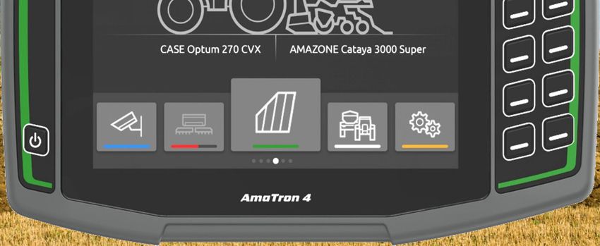
Service Training

5. Main view with app carousel
Functions of the app carousel:                                                                                        1
(1) Message bar
(2) Display of the active implement and the active tractor. Please note: check whether the
    geometry data and the source for the speed signal are suitable for the current tractor.
(3) In the Main menu, scroll through the application carousel by swiping to the left or right.      2
(4) The application carousel contains the following applications, as shown at the bottom left and
    right. If the representation is only faintly visible, the activation is missing.
                                                                                                                  3

  4     Button              Application          Function

                            Universal Terminal      Show implement controls for the connected
                                                                  implement

                            AUX-N assignmt       Configure connected AUX-N input device
                   (10)

                            Setup menu           Configure AmaTron 4

                            Tractors and         Configure tractors and implements
                            implements

                            Map View             Open map view

                            Camera               Showing the camera image

2021 / Status 01                                                                                                  Page 7
Service Training

  6. Geometry and sensors
  Create new tractor: Select Main menu > Tractors and implements.
  2. Create a new tractor (1).                                                               1
  3. Enter the tractor name (2).
  4. Confirm the name.                                                               2

  With the tractor geometry data (3), the position of the GPS receiver relative to
  the longitudinal axis, rear axle and to the attachment point on the tractor are
  specified. The geometry data is needed to correctly display the map view and                       3
  for proper functioning of part-width section control.

                                                                                                     2
  Select the tractor's speed signal: select Main menu > Tractor and
                                                                                                 3
  implements.                                                                                                          4
  1. Select the desired tractor under "Tractors" (1).                                                                  5
  2. Select "Sensors" (2).                                                               1
  3. Select "Wheel" (3).
                                                                                                                       6
  4. If the wheel sensor signal should be used, activate "Send signal" (4).
  5. If the wheel sensor signal from the GPS signal should be simulated, select
     "GPS receiver" under "Source", or if the wheel sensor signal comes from
     a wheel sensor, select "Signal socket" under "Source" (5).
  6. Teach in the pulses (6).

2021 / Status 01                                                                                                   Page 8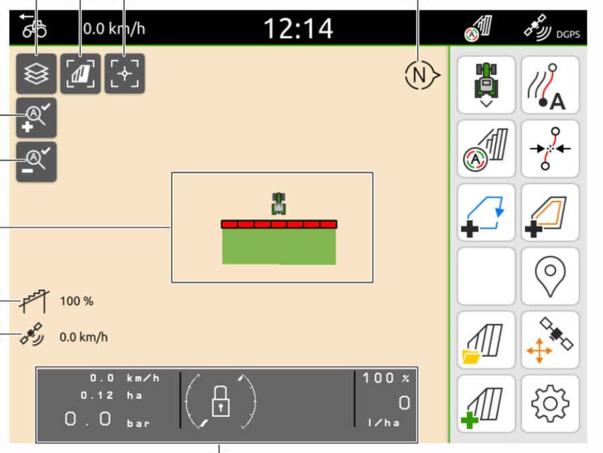
Service Training

7. Two-terminal solution
Changing the universal terminal: change from where the
implement is currently signed in; in some cases, this can
also be the tractor terminal. The selection of the UT
(universal terminal) and TC (Task Controller) number is
                                                              1
explained as an example in the UT of the AmaTron 4.
Example: operation of the implement on the tractor terminal                        3
and Section Control on the AmaTron 4. Implement software      2
> Profile / User menu > ISOBUS
(1) Terminal for implement operation on 1.                        4
(2) Terminal for documentation and Section Control on 2.
(3) Confirm the changes.                                              5   6
(4) Then confirm the settings.

To ensure a clear assignment between the universal
terminals (UT) and the implement, the UT and TC numbers
can also be configured manually on the AmaTron 4.

Example for changing the UT number:
(5) Change to the setup menu.
(6) Press the "ISOBUS" button.
(7) Press the "UT number" button.
(8) Change the UT number (most UTs have the UT                        7   8
     number set to No.1 ex factory, so simply select 2) to
     enable clear identification.
(9) Confirm the entry.
                                                                      v
(10) The AmaTron 4 must then be restarted!

                                                                                         9

2021 / Status 01                                                                        Page 9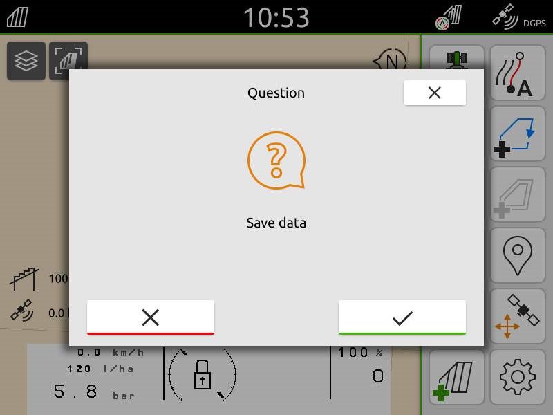
Service Training

8. Job data import / export
Importing ISO-XML job data:
ISO-XML job data must be saved as an ISO-XML file with the
                                                                        3
name "TASKDATA" in the "TASKDATA" folder in the main
folder of the USB flash drive.                                      2
(1) Insert a USB flash drive
(2) Open the quick-start menu.                                  1
(3) Select "Import ISO-XML". The AmaTron 4 imports the job
                                                                                          4
    data from the USB flash drive.
(4) Press the "Field menu" button.
(5) Select and actuate the desired field with the application
    map.
(6) Pull down the scroll bar
(7) The loaded application map can be seen in the preview.
(8) The selected job must be activated.                                 5
(9) Confirm the job.
                                                                                              6

Recorded job data can be exported as ISO-XML job data
and saved to a USB flash drive.
(10) Open the quick-start menu.
(11) Select "Export ISO-XML".
                                                                                8

                                             10
                                                     11                     7

                                                                                      9

2021 / Status 01                                                                              Page 10
Service Training
8. Job data import / export
Importing shape application maps:
1 3
(1) Insert the prepared USB flash drive with the application map 4
shape file into the USB port of the AmaTron 4.
(2) Press the "Open field menu" button.
(3) Actuate the "+" button to create a new field. Give the field an
2
unambiguous name. Confirm the entry.
(4) "Actuate" the newly created field.
(5) Press the "Shape import" button.
(6) The application maps and the attributes of the application
map(s) on the USB flash drive will be shown. Mark the
desired attributes.
(7) Press the "Unit" button. 6 7
(8) Select the corresponding units for the utilised implement.
(9) Confirm the settings.
(10) There is the option of editing the target rates on the map. You
can change all of the rates by a desired percent value. Press 5
the "Scale values" button.
(11) Confirm the settings.
8
Exporting job data as a PDF: 10
(12) Open the quick-start menu.
(13) Select "Export as PDF". 12 9
11
13
2021 / Status 01 Page 11Service Training
9. GPS switch
2 3 4
By actuating one of the buttons, the "GPS 1
switch" map view is opened.
5
6
(1) Selecting map layers
(2) Activate bird's-eye view 7
(3) Focus on the tractor and implement
(4) Compass 8
(5) Define the maximum zoom level 9
(6) Define the minimum zoom level
(7) Symbols for tractor and implement
(8) Degree of overlap
(9) GPS speed
(10) Implement information 10
(11) Invert direction of travel
(12) Create track line
(13) Activating automatic part-width section control 11 12
(14) Shifting the track lines
13
(15) Create a field boundary 14
(16) Virtual headlands
(17) No function 15 16
(18) Create marking
(19) Open the field menu 17 18
(20) GPS drift correction
(21) Generate new field 19 20
(22) GPS switch settings
21 22
2021 / Status 01 Page 12Service Training
10. GPS switch settings
To go to the settings for the GPS switch, actuate the
"Settings" button (1). By actuating the "Overlap" button (2),
the settings for the overlap are shown.
2
(3) Overlap in the direction of travel: here, the switch-on
and -off point in the direction of travel can be configured.
A positive overlap causes the implement to switch on
earlier or switch off earlier. A negative overlap causes the
part-width sections to switch on later or switch off later.
1
(4) Degree of overlap: the degree of overlap defines the
coverage at which individual part-width sections should
be switched off when reaching an area that was already
worked. The setting depends on whether complete
treatment is required or if double treatment should be 7
3
avoided (7).
4
(5) Overlap tolerance: the overlap tolerance defines the
tolerance with which the two outer part-width sections 5
(right and left) react to overlaps. The maximum value is 6
half the working width of the outer part-width sections.
The overlap tolerance prevents the outer part-width
sections from constantly switching on and off when there
is minimal overlap.
(6) Overlap tolerance at the field boundary: for safety
reasons, 0% degree of overlap must always be set at
the field boundary. The overlap tolerance can be
separately set for the field boundary at one's own risk.
2021 / Status 01 Page 13Service Training
11. Procedure during operation
Creating a new field:
(1) If you want to work without Task Controller documentation and
the internal implement documentation is sufficient, you only have
to press the "Create new field" button when starting a new job.
(2) When asked if you want to save the data, say no.
(3) If you want to work with the Task Controller, you must confirm
the question as to whether you want to save the data. 2 3
(4) Then create a new job and start it.
1
For previously created ISO-XML files and shape files, look at pages
10 and 11.
6
Activating automatic part-width section control:
(5) Press the "Activate automatic part-width section control" button. 5
(6) On the status line, the status to the automatic part-width section
control can be seen. 7
Status of the automatic part-width sections (7):
Grey and flashing: the implement is not in working position (check
4
requirements).
Red: the part-width sections are switched off or overridden by the
user.
Green: the part-width sections are switched on.
Yellow: the part-width section status (0/1) does not match with the
implement.
Orange: the part-width sections are switched off by Section Control.
2021 / Status 01 Page 14SmartLearning app Info Portal
The AMAZONE SmartLearning app offers Our Info Portal provides a wide variety of
video training courses for the operation of documents for viewing and downloading at
Amazone implements. The video training no charge. These can be technical and
courses can be downloaded onto your promotional printed material as an
smartphone if necessary, and are therefore electronic version or also videos, Internet
available offline. Simply select the desired links and contact data. Information can be
implement for which you want to watch a obtained by mail and subscriptions to new
video training course. published documents from different
categories are available.
www.info.amazone.de/
AMAZONEN WERKE H. Dreyer GmbH & Co. KG
Postfach 51 ꞏ D-49202 Hasbergen-Gaste
Tel. +49 (0)5405 501-0 ꞏ Fax: +49 (0)5405 501-147
www.amazone.de ꞏ www.amazone.at ꞏ email: amazone@amazone.de MG7186You can also read