OWNER'S MANUAL FOR DRY VACUUM PUMP MODEL: 2019
←
→
Page content transcription
If your browser does not render page correctly, please read the page content below
OWNER’S MANUAL FOR
DRY VACUUM PUMP
MODEL: 2019
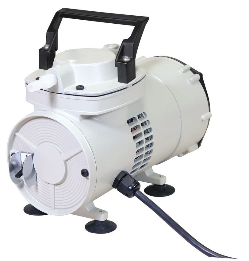
Model 2019B Model2019C
WARNING
Be sure to properly identify intake and exhaust before using the pump See
Section 3.15
CAUTION
Do not pump liquids with the pump. Pumping liquids will cause the pump to stop
working
Part No. 642913
Printed in USA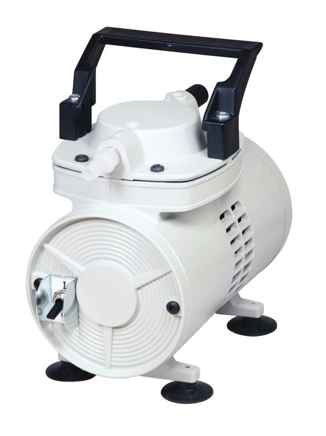
INSTRUCTION
                             WARNING AND CAUTION
                         PLEASE READ BEFORE OPERATION

            While reading your manual, please pay close attention to areas labeled:

                                   WARNING AND CAUTION.

                             The description of each is found below.

                                          WARNING
         Warnings are given where failure to observe instruction could result in injury or
                                        death to people

                                           CAUTION
            Cautions are found where failure to observe the instruction could result in
                 damage to the equipment, associated equipment and process

          These units conform to the SI International system of units of measurement.

The following symbols (with recommendation of IEC 61010 ) of warning will be found on the pump.

                             Caution - Refer to accompanying documents

                             Caution - Risk of electrical shock

                             Caution - Hot surface

                                            WARNING
        Motor includes a self resetting thermal cutout and the pump could restart without
                                 actuation under fault condition

                                                2
TABLE OF CONTENTS
Section Page
Section 01 - Safety Information
1.10 Caution: to prevent injury 4
1.20 Caution: to reduce risk of electrical shock 4
1.30 Warning: to reduce risk of electrocution 5
1.40 Warning: to reduce risk of explosion or fire 5
Section 02 - Optional Accessories
2.10 Optional Accessories 5
Section 03 - Installation
3.10 Environmental conditions 6
3.11 Introduction 6
3.12 Unpacking 6
3.13 Pump mounting 6
3.14 Pump location 6
3.15 Discharge provisions 7
3.16 Electrical power 7
3.17 Traps 8
3.18 When to Use a liquid Trap 8
3.19 When to Use a cold Trap 8
3.20 The care of a liquid trap 8
3.21 The care of a cold trap 8
Section 04 - Operation
4.10 Starting a Welch DRY Vacuum Pump 9
4.11 Cleanliness 9
4.12 Leak detection 9
4.13 Operating pressure range 9
4.14 The effects of unwanted vapor 9
4.15 Shutdown procedure 9
Section 05 - Maintenance
5.10 General maintenance 10
5.11 Diaphragm replacement 10
Section 06 - Specifications
6.10 Specification 11
Section 07 - Drawing
7.10 Exploded view and kits 12
Section 08 - Warranty
8.10 Warranty 13
3Section 1: SAFETY INFORMATION
1.10 Caution: To Prevent Injury...
1.11 Never operate this product if it has a damaged cord or plug. If it is not working properly, has been
dropped, damaged or has fallen into water, please return the product to a Welch service center for
examination and repair.
1.12 Keep the cord away from heated surfaces. All electrical products generate heat. To avoid serious
burns never touch unit during or immediately after operation.
1.13 Never block any air openings or place it on a soft surface where the openings may be blocked. To
ensure proper ventilation, keep unit a minimum of one inch from any wall or obstruction. The air
openings are for ventilation of the motor inside the housing.
1.14 Model 2019 is thermally protected and can automatically restart when the protector resets. Always
disconnect power source before servicing.
1.15 Never drop or insert fingers or any other object into any openings.
1.16 Do not operate this product where oxygen is being administered.
1.17 Wear safety glasses and goggles when operating this product.
1.18 Use only in well ventilated areas. The motor on all pumps are totally enclosed fan cooled
WARNING
Do not operate the pumps in an atmosphere containing flammable or explosive
gases/vapors
1.19 Be sure to properly identify intake and discharge before using pump. Models 2019 has one exhaust
port on the pump. See Section 3.15.
WARNING
Remove plug from Exhaust Port before using
1.20 Caution: To Reduce Risk Of Electrical Shock.
1.21 Do not disassemble. Disassembly or attempted repairs if accomplished incorrectly can create
electrical shock hazard. Refer servicing to qualified service agencies only.
1.22 Unit is supplied with a three pronged plug. Be sure to connect pump to a properly grounded outlet
only.
41.30 Warning: To Reduce Risk of Electrocution.
1.31 Do not use this product in or near area where it can fall or be pulled into water or other liquids.
1.32 Do not reach for this product if it has fallen into liquid. Unplug immediately.
1.33 Never operate this product outdoors in the rain or in a wet area.
1.40 Danger: To Reduce Risk of Explosion or Fire.
1.41 Do not use this pump in or near explosive atmospheres or where aerosol (spray) products are being
used.
1.42 Do not use this product near flames.
WARNING
Failure to observe the above safety precautions could result in Severe bodily
injury, including death in some cases
Section 2: OPTIONAL ACCESSORIES
Model 2019 Accessories
Catalog Number Description
1423B Inlet / Exhaust separator jar
331030-5 5 feet of thick walled rubber vacuum hose
1475K-21 Hydrophobic in-line filter, 10 pack, 0.2 micron
1412D Exhaust silencer
See website www.welchvacuum.com for ordering.
5Section 3: INSTALLATION
3.10 Environmental Conditions
The Pump is rated for indoor use only. Maximum altitude 2000 meters. Operating temperature
range 100C to 400C. Maximum relative humidity of 80% for temperatures up to 310C decreasing to
50% at 400C. Rated for +/-10% of supply voltage. Pollution Degree 2, Installation Category II.
3.11 Introduction
This manual has been compiled not only for the care and maintenance of the Welch Vacuum pump
now in your possession, but as a helpful reference and guide to prevent many problems which can
occur if used improperly.
3.12 Unpacking
Carefully remove the Vacuum pump from the shipping case. Preserve all paperwork for future
reference. If damage has occurred from shipment a claim must be filed with the carrier immediately;
preserve the shipping carton for inspection by the carrier. If you are required to communicate with
your dealer or Welch Vacuum be sure to include your order numbers for quick identification. Do not
return the pump to the factory without obtaining returned goods authorization.
*See “Service & Support” on www.welchvacuum.com.
3.13 Pump Mounting
Rubber feet are attached to the pump casing.
3.14 Pump Location
WARNING
Don’t operate this pump in an atmosphere containing flammable or explosive gas
WARNING
The motor is thermally protected and will automatically restart unexpectedly
when the overload device resets
The Vacuum pump should be located preferably in a clean, dry and well ventilated area. Please be
sure not to block the ventilation ports located on the motor housing. The pump should be placed
where the surrounding temperature remains between 100C and 400C (500F and 1040F). Always
check to insure the location chosen is protected from direct or indirect moisture contact. The pump
should be located as closely to its system in order to utilize it most efficiently.
3.15 Discharge Provisions
Vacuum Pump Model 2019 comes with two hose barbs, one Intake and one Exhaust. All hose barbs
and mufflers are supplied loose with the pump. The hose barb used on all models accepts 3/8” I.D.
hose. By threading the hose barb in the exhaust port of the pump, a vent line can be attached which
allows gases and vapors pumped through the pump to be piped from the work area into a hood.
Vent lines will muffle noise coming from the vacuum pump.
6WARNING
Never block the discharge port. If the exhaust is blocked, pressure will build-up
in the pump which can lead to the pump head bursting creating the potential of
serious injury. Remove plug from exhaust port
WARNING
Remove plug from exhaust port before operating
Properly identify the intake and exhaust of the pump
Exhaust - Muffler p/n 1412D
Intake - Hose barb fitting,
1/4” NPT x 3/8 ID hose
3.16 Electrical Power
3.16.1 Power Source Review
Review the power source and the motor rating to be sure they agree in voltage, phase and
frequency. Serious damage may occur to the motor if it is connected to an improper voltage. All
Welch pumps must be grounded. Grounding reduces the risk of electric shock in the event of an
electrical short circuit. The plug must be plugged into an outlet properly grounded. Consult your
local electrical codes if you have doubts.
Identification Symbols: Power On Power Off
73.17 Traps
3.18 When to Use a Liquid Trap
When pumping gases or low vapor loads, a trap is not necessary unless you want to capture
vapors evolved from the process. When a heavy load of water or organic vapor is evolved from
the vacuum process, condensation of vapor in the pump mechanism may occur. The reason is the
pump is compressing the vapor as it passes through the pump. If the vapor is dense enough, the
compression will cause condensation of the vapor in the pump mechanism. The valve system in the
pump mechanism is designed to pass the small quantity of liquefied vapor formed when pumping
heavy vapor loads. The liquid formed will be ejected from the exhaust port. The ejected liquid
from the exhaust port can either be collected in a liquid trap attached to the exhaust port or the
vapor trapped in a cold trap placed in-line between the pump and the vacuum chamber. A simple,
inexpensive liquid trap can be made from a filtering flask. The filtering flask is connected by 3/8”ID
hose to the exhaust port by using the loose hose barb provided.
3.19 When to Use a Cold Trap
The use of a cold trap when pumping heavy vapor loads will eliminate the need for a liquid trap
attached to the exhaust port. The cold trap is installed between the pump and the vacuum chamber.
The water or organic vapors evolved from the vacuum process will upon entering the cold trap will
come in contact with the surfaces of the trap and condense. Commonly used refrigerants are liquid
nitrogen or dry ice with alcohol slurry. Dry ice provides sufficient cooling to freeze out most heavy
water vapor loads. A variety of cold traps are available from Welch. Please call our customer service
department. For additional information at (847) 676-8800.
3.20 The Care of a Liquid Trap
A liquid trap needs no refrigerant. The key maintenance issue when pumping high vapor loads is to
regularly drain the trap of liquid ejected from the dry vacuum pump.
3.21 The Care of a Cold Trap
When using a cold trap the refrigerant should be maintained at a high level in the flask to keep
the trap at a uniformly low temperature. If the trap is rewarmed it may allow re-evaporation of the
condensate. The refrigerant add tube on the liquid nitrogen trap should not be obstructed as the
refrigerant boil-off can produce dangerously high pressures. If the trap becomes saturated it should
be disconnected from the system, drained and cleaned. An increase in pressure in the vacuum
system will normally indicate that the trap has become saturated. To clean the trap, remove the trap
from the system and allow the trap to warm up and rinse off the condensate with a suitable solvent
in a fume hood. Thoroughly clean and dry the trap before reinstalling into the system. If a liquid
nitrogen trap is used, the refrigerant add tube on the liquid nitrogen trap should not be obstructed as
the refrigerant boil-off can produce dangerously high pressures.
8Section 4: OPERATION
4.10 Starting a Welch Dry Vacuum Pump
Before attaching the pump to a system it is well to familiarize yourself with the function and action of
the pressure vacuum pump which you have acquired. Review the power requirements as described
in Section 3.16. Welch recommends running the pump for a few minutes to warm it up before use.
The warm-up improves the pumps ability to pass water and organic vapor. A warm pump will handle
more vapor without liquefying it than a cold pump.
4.11 Cleanliness
Take every precaution to prevent foreign particulates or liquid from entering the pump. Particulates
will damage the pump’s performance. If you find that particulates or liquid will come off during
the process of evacuation, a simple liquid trap can be made out of readily available material for
protecting the pump. The trap would consist of a filtering flask placed between the pump and the
vacuum chamber.
4.12 Leak Detection
Eliminating all leaks in a vacuum system is a key to obtaining maximum vacuum. The pump must
remove this added volume of leaked gas to maintain the desired vacuum. Leaks can be located by
slightly pressuring the system and painting the suspected area with a thick soap solution. Escaping
air will produce soap bubbles.
4.13 Operating Pressure Range
Vacuum pumps are designed to be run from slightly below atmospheric to their maximum vacuum
level on the intake side. Consult the Specification Table in the back of this manual for the ratings for
your specific model.
4.14 The Effects of Unwanted Vapor
Systems which contain undesirable vapors cause difficulty both from the standpoint of attaining
desirable ultimate pressures. A vapor is defined as the gaseous form of any substance which is
usually a liquid or a solid. Water, oil, and mercury vapors are three of the more common vapors
encountered in typical vacuum systems. When such vapors exist in a system, the vapors or
mixtures of gas and vapors are subject to condensation within the pump; the precipitated liquid may
thus ultimately solidify on the heads and diaphragm causing corrosion.
4.15 Shutdown Procedures
After use, Welch recommends the pump be run for about 2 minutes disconnected from the
vacuum process. The air pumped through the mechanism will purge out water vapor or droplets of
condensate that may have formed on the inside of the pump. This purge of the pump mechanism
helps prevent build up of solute crystals inside of the pump head. Over time, these crystals will
shorten pump lifetime.
9Section 5: MAINTENANCE
5.10 General Maintenance
Welch Vacuum units are 100% oil-free. All bearings are sealed and permanently lubricated.
Lubrication should not be attempted. The units are built for duty operation just like a water aspirator,
but with the quietness, performance and durability of a diaphragm.
5.11 Diaphragm Replacement
WARNING
Do not remove the diaphragm unless you are wearing hand protection. The steel
disc inside the diaphragm may cause harmful injury
Component parts required
1. Diaphragm & diaphragm liner.
2. Four screws for intake valve plate.
Head screw
Disassembling the diaphragm & liner
1. Disconnect power. Valve plate screw
2. Disconnect air lines and remove pump from enclosure.
3. Observe the position of the air intake and exhaust Valve plate
ports before disassembly.
4. Remove six screws (1) from head, remove head, set Diaphragm
head with screws aside for assembly.
5. Remove four screws (2) from valve plate. Remove Connecting Rod Top
valve plate and set aside for reassembly.
6. Remove diaphragm & liner and discard.
Reassembling the diaphragm & liner
1. Wipe top of connecting rod clean with a soft clean
cloth.
2. Place new diaphragm & liner on top of connecting rod.
Line up the holes in the diaphragm & liner with the
screw holes in connecting rod. Replace valve plate
and line up holes.
3. Torque valve plate screws to 20 inch-pounds using
crisscross pattern.
Caution: To prevent damage to the pump, never
apply any sealant or lubrication to the gasket.
Gasket
Head valve plate replacement
1. Wipe inside of head clean. Install new gasket if
Head valve plate
needed, be sure to remove any excess gasket.
2. Replace valve plate in head. Chamfer side of valve
Valve plate screw
plate should face you. Insert four new screws. Torque
valve plate screws to 22 inch-pounds.
10Reassembling the pump.
1. Place the head assembly on the housing, observing the
position of the air intake and exhaust ports.
Note: Make sure the diaphragm is seated properly in the well
of the housing and head. Do not pinch the diaphragm or liner.
2. Insert the head screws and tighten each screw until it is snug
in a criss cross pattern. Do not completely tighten the screws
yet.
3. Using a torque wrench with the T-25 Hex attachment, tighten
each head screw to 45 inch-pounds, in a criss cross pattern.
Caution: To avoid property damage or personal injury,
always try rotating the fan by HAND, prior to connecting the
unit to the power source. Check for suction at the air inlet
port by placing your finger over the port as you turn the fan.
You should feel a slight suction with each rotation of the
fan. If you don’t feel suction, or if you feel or hear a thump
as you turn the fan, DO NOT CONNECT THE UNIT TO
A POWER SOURCE; review the assembly procedure for
possible error.
Section 6: SPECIFICATIONS
6.10 Specification
Welch Model 2019B-01 2019C-02
Free air Displacement
CFM (L/min) @ 60Hz 1.3 (36) 1.3 (36)
CFM (L/min) @ 50Hz 1.1 (30) 1.1 (30)
Maximum Vacuum InHg 24 24
Ultimate Pressure Torr (mbar) 150 (200) 150 (200)
Maximum Continuous Pressure PSIG 18 18
Tubing needed, I.D., inches 1/4 1/4
Weight, Ibs (kg) 10.2 (4.6) 11.2 (5.1)
Cord North American 115V Plug European Schuko Plug
Motor H.P. 1/15 1/15
Motor Voltage & Frequency 115V, 60Hz, 1 Phase 230V, 50Hz, 1 Phase
Motor Amps 3.5 1.7
Overall Pump Dimensions 8.75 x 5.0 x 8.75 10.4 x 5.0 x 8.75
L x W x H inches (cm) (22.2 x 12.7 x 22.2) (26.4 x 12.7 x 22.2)
Carton Dimensions 15.31 x 12.31 x 12.69 15.31 x 12.31 x 12.69
L x W x H inches (cm) (38.9 x 31.3 x 32.2) (38.9 x 31.3 x 32.2)
Shipping Weight, pounds (kg) 12.4 (5.6) 13.4 (6.1)
11Section 7 - DRAWING
7.10 Exploded view and kits.
Diaphragm replacement kit 2019K-01. Pump head and rebuild kit 2019K-03.
8
7
5
6
4
9 10
3
2
1
11
Item Description 2019K-01 2019K-03 2500K-04
1 Diaphragm, Buna N 1 1 -
2 Diaphragm liner, PTFE 1 1 -
3 Diaphragm Hold Down Plate - 1 -
4 Valve Plate Assembly - * -
5 O-Ring Gasket, Head 1 * -
6 *Pump Head Assembly Includes item 4 and 5 - 1 -
7 Head Screws - 4 -
8 Handle Screws - 2 -
9 Diaphragm Hold Down Screws 4 4 -
10 Hose Barb PVDF 1/8” NPT x 1/4” ID Hose - 2 -
11 Rubber Suction Cup Feet - - 4
12Section 8: WARRANTY
8.10 Warranty
UNPACKING
Inspect the pump carefully. If any damage has occurred, file claim with the carrier immediately. Save the
shipping container for carrier to inspect.
OPERATING PUMP
Refer to the enclosed Instruction/Operation Manual for all information to properly operate and maintain
the pump.
WARRANTY
This Welch Vacuum product is warranted to be free from defects in material and workmanship. The
liability of Welch-Ilmvac under this warranty is limited to servicing, adjusting, repairing or replacing any
unit or component part which in the judgment of Welch-Ilmvac has not been misused, abused or altered
in any way causing impaired performance or rendering it inoperative. No other warranties are expressed
or implied. The method of executing this warranty: servicing, adjusting, repairing or replacing shall be at
the discretion of Welch-Ilmvac. Vacuum pumps that have been used for any period, however short, will
be repaired under this warranty rather than replaced.
The warranty is effective for one year from the date of original purchase when:
1. The warranty card has been completed and returned.
2. The product is returned to the factory or other designated service centers, freight prepaid.
3. The product in our judgment is defective through no action or fault of the user.
If the product has become defective through misuse, abuse, or alteration, repairs will be billed regardless
of the age of the product. In this event, an estimate of the repair costs will be submitted and authorization
of these charges will be required before the product is repaired and returned.
To obtain a return authorization number, please fill in the on-line request form on
www.welchvacuum.com. Products without a return authorization number will be refused by our receiving
department. Before shipping, properly pack the pump, insure it against loss or damage, and on the
outside of the pump packaging and the packing slip write in the return authorization number. Pumps
damaged due to improper packaging are the customer’s responsibility.
13Welch by Gardner Denver
1601 Feehanville Drive, Ste 550
Mount Prospect, IL 60056
Phone: (847) 676-8800 (Technical Support)
Fax: (847) 677-8606
E-Mail: gdwelchvacuum@gardnerdenver.com
Web-Page: www.welchvacuum.com
Copyright© 1997-2007 Gardner Denver Welch Vacuum Technology, Inc.
Welch is registered trademarks of Gardner DenverYou can also read