Packers and Liner Hangers - Basic Overview Applications and Selections of Packers Setting Criteria and procedures
←
→
Page content transcription
If your browser does not render page correctly, please read the page content below
Packers and Liner Hangers
• Basic Overview
• Applications and Selections of Packers
• Setting Criteria and procedures
What is a Packer?
• A packer is a tool used to form an annular seal
  between two concentric strings of pipe or between
  the pipe and the wall of the open hole.

• A packer is usually set just above the producing
  zone to isolate the producing interval from the
  casing annulus or from producing zones elsewhere
  in the wellbore.

• Separates fluid types (or ownership), protects
  against pressures and corrosion.

Why are packers used?
• Tubing and packer used to isolate zone of interest
  - can be removed for repair.
• Packers act as downhole valve for press control.
• Packer can be a temporary plug to seal off the
  zone while work is done up the hole.
• Subsurface safety valves used with packers for
  downhole shut-in.
• Focus flow
• Isolate between zones
Packer Cutaway Drawing
           As the packer sets, the inner mandrel moves up,
           driving the cone underneath the slips, pushing them
           into the casing wall. The sealing element is
           compressed & extruded to the casing wall.

             Lock Ring and Mandrel
             Slips
             Cone
              Seal
              Inner Mandrel
             Ability to effectively set a packer depends on
             having a clean, non corroded set point and
             reaching the set point without fouling the slips or
             failing other components.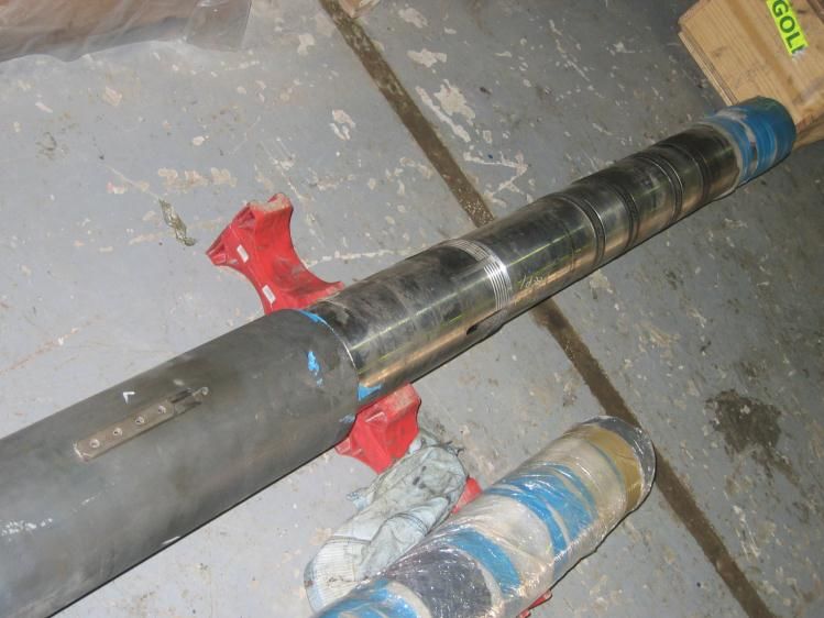
Packers and Liner
Hangers
Mechanical isolation methods

Two examples:
1. An external casing packer (ECP)
   set to seal the annulus between the
   surface or protection string and the
   inner, production string
2. A conventional packer set near the
   end of the tubing, that isolates the
   inner annulus from the tubing.
Packer Considerations
 • Force on an area
Remember, it’s a
force balance.           Area down =
                         casing ID - tube OD

                         Area up =
                         tube x-section +
                         casing ID - tube OD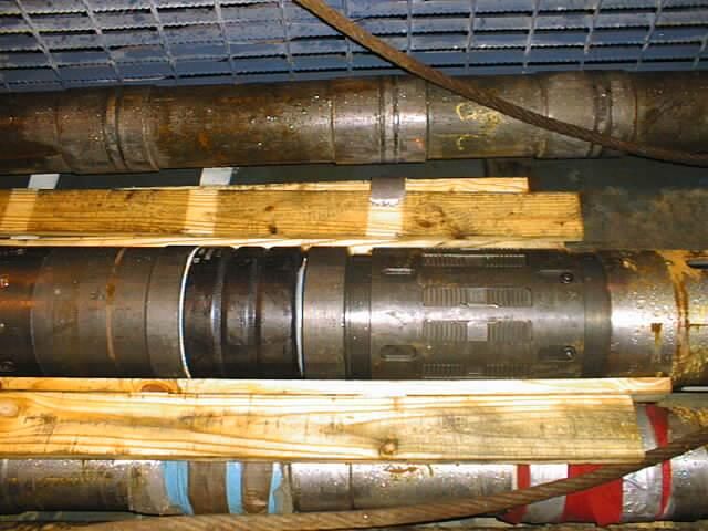
Packer Types & Selection
                          Production Packers

Retrievable                                      Permanent
               Wireline Set
 Sealbore                                             Hydraulic Set
               Hydraulic Set

               Hydrostatic Set        Single          Wireline Set
Hydraulic
               Differential Set       Dual

Mechanical      Single Grip
                                  Mech. Slips
               Double Grip
                                  Hyd. Slips
 Multiport     RMC

               ESP
                                                Schlumberger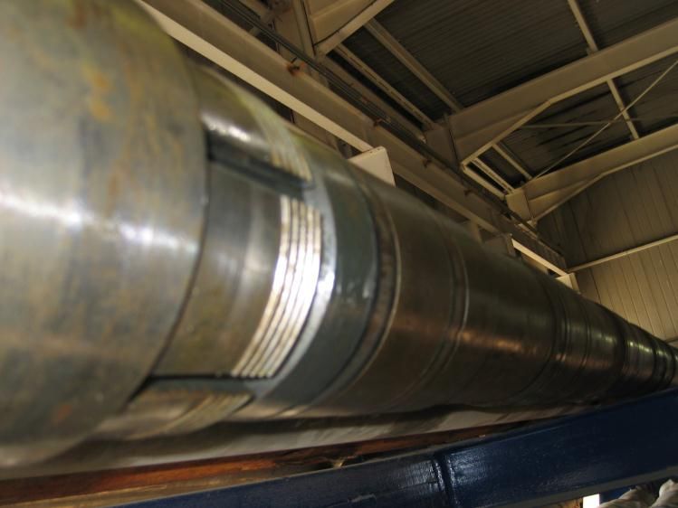
Specific Packer Examples
• Packer Examples
  –   Retrievables
  –   Seal bores
  –   Inflatables
  –   Wash Tools
Retrievable Packers
•   Expected to be retrieved
•   More prone to leaks
•   Need an equalizing port
•   Release mechanism must be possible with
    well design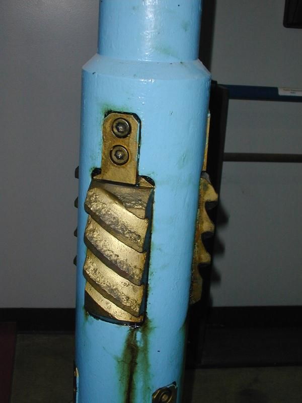
Retrievable Packers

                  Tension Set - Economical packer used in
              production, injection, zone isolation applications

              • Compact
              • Simple J slot control for set and release
              • Shear ring secondary release
              • Right-hand safety joint emergency release
              • Rocker type slips
              • Can be set shallow
Weatherford
Retrievable Production Packers
Mechanical - Used in production, injection,
fracturing, zone isolation and remedial applicatuions
• Rotation set and release
• Can be set with tension or compression
• Tubing can be landed in tension, compression or neutral
• Models rated up to 10,000 psi
• Pressure equalization needed prior to upper slip release
• Secondary shear release required
WeatherfordRetrievable Production Packers
Mechanical Used in production, stimulation and
testing
• Compression set
• RH rotation required to set, (LH option usually
available)
• Available with or without Hydraulic hold down
buttons for differential pressure from below
• By-pass needed for equalization of pressure, and for
running and retrieval without surging/swabbing the
well.
WeatherfordRetrievable Packers
Wireline set - Used in production, injection,
fracturing, zone isolation and remedial applications
where wireline setting is preferred
• Can act as a bridge plug prior to production
• Connect to tubing via On/Off Tool with blanking plug
• Tubing can be landed in tension, compression or neutral
• Slips above and below the elements
• Triple element pack off system
• Pressures to 10,000 psi
• Fluid bypass needed for pressure equalization
• Retrieved on tubing
• Secondary shear release needed
WeatherfordSeal Bore Packers
• Allow tubing movement; however:
– Too much contraction can pull seals out of PBR
– Seals can “bond” to the seal bore over long
time at higher temperatures
– Debris on top of packer can stick assemblyUnprotected seals below the packer may allow seal swelling by gas and fluids, causing seals to roll off if the stinger is pulled out.
Deep Completions
• Most typical is permanent packer with a
  PBR (arrangement depends on personal
  preferences, individual well configurations
  and intended operations).
• Seal assembly length dependent not only on
  normal operations, but also fracturing, kill
  and expected workovers.
Seal Bore Packers

              • High pressure & temperature ratings available
              • Multiple packing elements available
              • Short units are desirable for use in tight doglegs (>5o) and high
                (>8o/100ft) departure angles
              • Ability to set on wireline or with a hydraulic setting tool
              • Rotationally locked units needed for mill-ability
              • Share Seal Assemblies with permanent seal bore packers
              • Critical metallurgical and seals (O-rings, etc) should be isolated
                from wellbore fluids by main elements.

Weatherford
Retrievable Seal Bore Packer
One-trip applications
• Hydraulic set version retrievable seal bore
packer available for one-trip installations
• Seal assembly is run in place for one trip
installation
• Available with large upper seal bore to
maximize ID
• Rotationally locked components
WeatherfordPermanent Seal Bore Packers
Used in one trip production applications
• Seals run in place for one trip setting
• A metal back-up system can be specified to
casing ID to prevent element extrusion
• Elastomer and materials available for
hostile environments
WeatherfordPacker Considerations • Select seals for full range of expected temperatures, pressures, and fluids. • A back-up system is need around the main seal to prevent seal extrusion at high temps and pressure. • Examine slip design to help avoid premature setting during movement through viscous fluids, doglegs and rough treatment
Seal Bore
                                  Packers

               Nitrile Seal or
               Viton Seal        Molded Seals:
               Steel spacer      • Recommended in medium pressure
                                   applications where seal movement out
         MOLDED SEAL
                                   of the seal bore is anticipated.
         SINGLE UNIT

                                    Chevron Seals:
                                                               End spacer
                 Used for higher pressure and
                                                                Seal spacer
                   temperature applications.
                                                                Middle spacer
                                       CHEVRON SEAL
                                        SINGLE UNIT             Nitrile Seal or
                                                                Viton Seal
Weatherford
Seal Bore Packer
Accessories
• Tubing Anchor and Locator Assemblies
• Seal Units and Spacer Tubes
• Seal Bore and Mill-Out Extensions
• Packer Couplings and Bottoms
• Pump-out, Screw-out, and Knock-out Bottoms
WeatherfordInflatable Packers and Plugs
• Reasons to run and inflatable.
– Need to set beneath a restriction.
– Need to set in open hole.
– In non-standard casing.
– Setting in multiple sizes of pipe on same run.
– Where larger run-in and retrieval clearances are
needed.
– Large diameter applications.Inflatable Setting Considerations
The inflatable packer offers a way to
set a seal in a larger area below a
restriction.
The quality of the seal depends on
how much the packer must expand
over initial diameter, the length of
the slide (placement run), the
Holding ability of the inflatable differential pressure it must hold,
is always suspect since it does what fluid is used for inflation and
not have conventional slips. the conditions in the area in which it
is set.
When deflating an inflatable packer, allow time (1 hr?) for relaxation of the elements. The
elements never shrink back to initial diameter – allow about 30% increase in diameter for
retrieval.Inflatables rely on expansion of an inner rubber bag that pushes
steel cables or slats against the wall of the pipe or the open hole.
The only gripping ability is generated by the friction of the steel
against the pipe or open hole. This is critically dependent on the
inflation pressure and the exterior slat or cable design. For a
permanent seal, place several bailers of cement on top of the
inflatable.
BakerPerforation Wash Tool
Used for selective acidizing of perforated
intervals
• Heavy Duty reinforced casing cups
• Spacing between cups adjustable from 12” to
any length by addition of standard tubing pup
joints
• Large internal bypass
• Cup wear from casing burrs can be significant
and may reduce seal, especially in long zones.
• The number of successful resets depends on
casing conditions, pressures, slide length
(running), temperature and deviation.
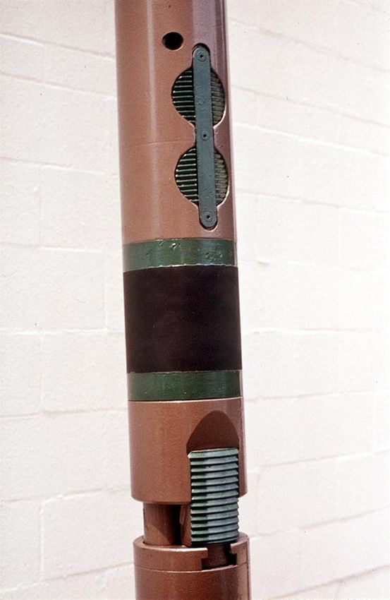
Weatherford Successful resets run from about 5 to over 20.Packer Seals Packer Slips
Lawrence Ramnath - TrinidadA hydraulic set packer. Note the lower slips set by movement of the mandrel and upper slips set by piston action.
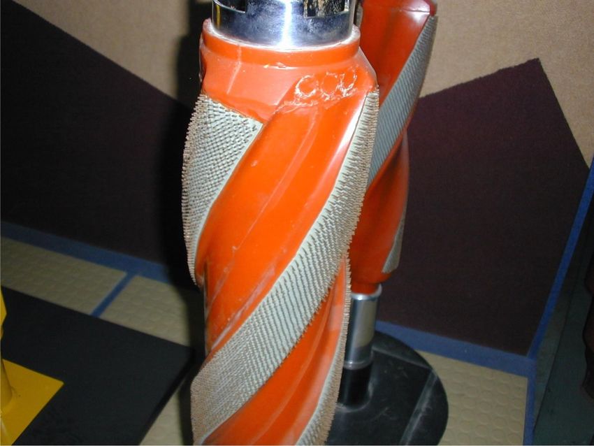
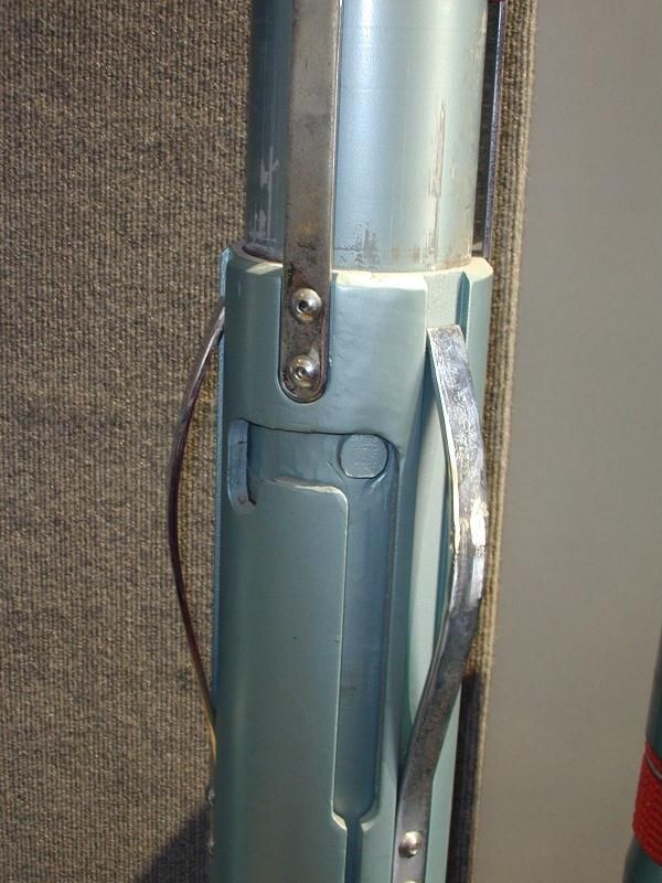
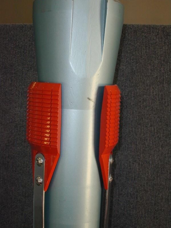
Slips – Liner hanger
J-Slot on a liner hanger.
Packer Comparisons - from Weatherford
                                     Weatherford Completion Systems                                                 HES                    Schlumberger
           Packer Type               (Bold Items are Preferred Products)            Baker                                                    (Camco)
                                                                                                     Halliburton           Guiberson
  Solid head, Tension Set,          PAD-1, PADL-1                           AD-1               RB                         Uni-Packer I     SA-3
  Mechanical, Single Grip                                                   AL                 R-4                                         T Series
  Compression Set, Mechanical,      PR-3 Single Grip                        R-3 Single Grip                               Uni-Packer IV    SR-2
  Single Grip                                                               Model G            R-4                        Uni-Packer II    U-3
                                                                                                                          G-4              CA-3, C Series
  Compression Set, Double Grip      PR-3                                    R-3 Double Grip    MHS                        Uni-Packer V     SR-1
  Packer                                                                                       MH-2
  Neutral Set, Double Grip Packer   QDG, QDH, Arrowset I-X (&10K), Ultra-   Lockset, Max       WPL                        Uni-Packer VI    SOT-1
                                    Lok, Double Grip                        J-Lok, MS          Perma-Lach                 G-6, G-16        KH
  Hydraulic Set Retrievable         HRP, Hydrow-I, PFH                      FH, FHL, FHS       RH                         Uni-Packer VII   Hydro-5
                                                                            Hydra-Pak          PHL                        G-77             HRP
                                                                            HS, HS-S           AHR                        RHS
  Dual Hydraulic Set Retrievable    Hydrow IIA                              A-5                RDH                        Uni-XXVII        Hydro-10
                                                                            T-2                BHD                        RHD              HSD
                                                                            GT
  Wireline Set Permanent            Arrowdrill B                            Model D            AWB                        G, GT            Model S
                                                                            F-1                BWB                        H, HT
                                                                                               AWS
  Wireline Set Permanent Double     Arrowdrill DB                           DA, DAB            AWR                        G-1, GT-1
  Bore                                                                      FA, FAB                                       H-1, HT-1
  Hydraulic Set Permanent           Arrowdrill BH                           SB-3               MHR                        PG               Model HS
                                                                                                                          PH
  Hydraulic Set Permanent Double    Arrowdrill DBH                          SAB-3              MHR                        PG-1             Model HSB
  Bore                                                                                                                    PH-1
  Retrievable Seal Bore             Arrow-Pak                               Retrieva-D, DB     VTL (Versa-Trieve)         G-10             M Omegatrieve
                                                                            WS, WSB                                                        Quantum
                                                                            SC-1, SC-2
  Hydraulic Set Retrievable Seal    Hydrow-Pak                              SC-2PAH            VHR (Versa-Trieve)         RSB
  Bore
  HPHT Hydraulic Set Retrievable    Hydrow-Pak                              HP-1AH, SC-2PAH    HPHT (Versa-Trieve
                                                                            HP/HT              Retrievable)
  Compression Set Service Packer    CST, C5, H/D, MSG                       EA Retrievamatic   RTTS                       HDCH-V           Omegamatic
                                                                                               Champ III, IV
  Compression Set Storm Packer      CSTH, DLT
  Tension Set Service Packer        32A, Fullbore Tension                   C Fullbore         BV Tension Packer                           R-104

  Tubing Set Retrievable Bridge     QDH w/ EQV, TSU                         G Lock-Set         3L                         RBP-VI           P-1
  Plug
  Wireline Set Retrievable Bridge   WRP, CE, CE2
  Plugs
  Permanent Bridge Plugs/Cement     PCR, Plugwell, PBP                      Mercury N, K-1     EZSV, EZ Drill             Type A           Quik-Drill
  Retainer                                                                                     EZ Drill SVB
                                                                                               Fas-Drill, HCS
Packer specifics from Baker
Casing Design Options – think about running and setting packers.

                      Mixed             Mixed              Monobore:
                      weights,          grades             mixed
                      same              and                grades,
                      grade             weights            same
                                                           weight

Small
diameters at
the top of the
well may
prevent entry
by some
packers.
Production Packers • Purposes – Casing protection from fluids or pressures – Separation of zones – Subsurface pressure and fluid control – Artificial lift support equipment
Packer Considerations
• Seal stability
  – pressure, temperature, fluid reaction
• Force balance and direction
  – slip direction
     • resists upward motion, downward or both ways)
     • tension, compression, mechanical or hydraulic set
Allowing Tubular Movement • Usually incorporate a PBR - polished bore receptacle, for a “stinger” or seal assembly to slide through. • Shoulder out on the PBR - if it can move, it will eventually leak. • Seals must match operating extremes as well as general conditions.
Seal Bore Packer to Tubing Connections

Seal Bore
Extensions
(SBE)                                Tubing
                                     Sealbore
                                     Receptacle
                                     (TSR)
Polished
Bore
Receptacle
(PBR)
Seal Assembly Locator Types
Locator Anchor
Latch
Snap LatchA “stinger” or seal assembly that is run on the end of tubing and “stings” into the polished bore receptacle (PBR) of the packer.
Stinger Seal Materials
• Single or mixture of elastomers
• seal design variance
• seals usually protect the slips from
  corrosive fluids.
Tubing Seal Stability
Seal Material         oil    brine     H2S   CO2
Butyl Rubber          4       1       1      2
Flurocarbon            1      1       4      2
Nitrile                1      1       4      1
Fluro-silicone         2      1       3      2

1=good, 2=fair, 3=doubtful, 4= unsatisfactory
Much larger data base available online.
Halliburton Energy Services                                                                                                                                     (1)

                         General Guidelines For Seals
  Compound                    PEEK(2), (4)       Ryton(2), (4)       Fluorel(3)           Aflas(3)          Chemraz(3)               Viton(3)             Neoprene(3)          Nitrile(3)      Kalrez(3)       Teflon(3)
                                                                      Filled              Unfilled           Unfilled           Filled Unfilled             Filled              Filled          Filled     Filled Unfilled
  Service °F                                                            350                  350                 450             350         325                 300              275            450         400         325
          (°C)                                                         (177)                (177)               (232)           (177)       (163)               (149)            (135)          (232)       (204)       (163)

              (2), (4)                                                                                                          Above       Below
  Pressure           psi                                              15,000               10,000              15,000            5000        5000              5000              3000          15,000      15,000       5000
                    (MPa)                                              (103)               (68.9)              (103)            (34.4)      (34.4)            (34.4)            (20.7)          (103)       (103)      (34.4)

  Environments
  H2S                             A                 A                    A                    A                   A                B           B                NR                NR              A           A           A

  CO2                             A                 A                    B                    B                   A                B           B                 C                 A              A           A           A
  CH4 (Methane)                   A                 A                    A                    A                   A                A           A                 B                B               A           A           A
  Hydrocarbons
  (Sweet Crude)                   A                 A                    A                    A                   A                A           A            B           C          A              A           A           A
  Xylene                          A                 A                    A                    C                   A                A           A                NR                NR              A           A           A
  Alcohols                        A                 A                    C                    B                   A                C           C                 B                 A              A           A           A
  Zinc Bromide                    A                 A                    A                    A                   A                A           A                NR                NR              A           A           A
  Inhibitors                      A                 A                   NR                    A                   A               NR          NR                NR                 B              A           A           A
  Salt Water                      A                 A                    A                    A                   A                A           A                 C                 A              B           A           A

  Steam                           A                 A                   NR                    A                   A               NR          NR                NR                NR             NR           B           B
  Diesel                          A                                       A                                       A                A                                                              A
                                                    A                                        NR                                                A                 B                 B                          A           A

    A-Satisfactory                           B - Little or no effect                         C - Swells                           D - Attacks                           NR - Not recommended                             NT - Not tested

NOTE: (1)     This information provides general guidelines for the selection of seal materials and is provided for informational purposes only. Seal Specialists with Halliburton Energy Services should be consulted for the actual selection of seals
              for use in specific applications. Halliburton Energy Services will not be liable for any damage resulting from the use of this information without consultation with Halliburton Seal Specialists.
        (2)   Contact Technical Services at Halliburton Energy Services - Dallas for service temperature and pressure.
        (3)   Back-Up Rings must be used.
        (4)   There could be a slight variation in both temperature and pressure rating depending on specific equipment and seal designs.
Halliburton Energy Services (1) General Guidelines For V-Packing
Halliburton Energy Services  (1)

General Guidelines For V-Packing
(1)
Packer Element Selection
START
STEAM/THERMAL
N
APPLICATION W/NO
HYDROCARBON FLUIDS
Chart PERMANENT
N Y
PACKER DESIGN
N
PACKER IN OIL BASE MUD
OVER 24 HOURS BEFORE
PACKER
IN BROMIDE
N
COMPLETION FLUIDS MORE THAN 36
HOURS BEFORE
TEMP
40°F TO
325°F
Y
NITRILE ELEMENTS
W/STANDARD METAL BACKUPS
SET? SET?
Y N Y Y N
Y
TEMP NITRILE ELEMENTS W/TEFLON
40°F TO AND METAL BACKUPS
400°F
N
Y
TEMP AFLAS ELEMENTS
100°F TO W/STANDARD METAL BACKUPS
400°F
N
Y
TEMP
AFLAS ELEMENTS W/TEFLON AND
100°F TO
GRAFOIL WIREMESH AND METAL BACKUPS
450°F
N
TEMP CHECK WITH YOUR HALLIBURTON
GREATER THAN 450°F REPRESENTIVE FOR SPECIAL APPLICATIONS
N Y
RETRIEVABLE PACKER TEMP
NITRILE ELEMENTS
PACKER EXPOSED TO 40°F TO
W/BONDED GARTER SPRINGS
DESIGN BROMIDES? 275°F
Y N
PACKER
N Y
ELEMENTS TEMP
EXPOSED TO AMINE
FLUOREL ELEMENTS
40°F TO W/BONDED GARTER SPRINGS
CORROSION
INHIBITORS? 400°F
Y N
Y
TEMP AFLAS ELEMENTS
100°F TO W/BONDED GARTER SPRINGS
400°F
N
CHECK WITH YOUR HALLIBURTON
TEMP REPRESENTIVE FOR SPECIAL
GREATER THAN 400°F APPLICATIONS
Y
TEMP EPDM ELEMENTS WITH BACKUPS
LESS THAN 550°F
NOTE: (1) This information provides general guidelines for the selection of seal materials and is provided for informational purposes only. Seal
Specialists with Halliburton Energy Services should be consulted for the actual selection of seals for use in specific applications. N
Halliburton Energy Services will not be liable for any damage resulting from the use of this information without consultation with Halliburton
CHECK WITH YOUR HALLIBURTON
Seal Specialists. TEMP
REPRESENTIVE FOR SPECIAL
GREATER THAN 550°F
APPLICATIONSForces and Length Changes
• Temperature:
• Piston Effect:
• Ballooning
• Buckling:
A tubing movement calculator is the best method, but the difficulty is in
knowing accurate temperature changes and pressure changes.Is it Force or Length Change? • No packer - tube suspended and not touching well bottom - length change • Tube landed on packer - incr. force with increasing temp, shortening possible with cooling after downward force absorbed. • Latched tubing - no movement, only forces • Tube stung through - length changes unless locator is shouldered • If tube set in tension or compression, effects of temp depends on initial force and DT
Temperature, length change
DL = CLDT

Where:
 DL = length change
 C = expansion coeff. for steel = 6.9x10⁻⁶/oF
 L = length of tubing
 DT = average temp change, oF
Temperature, Force change
• F = 207 DTa As

• Where:
    F = temperature induced force
    DTa = change in average temp of tubing, oF
    As = cross sectional area of tubing
What Temperature is Average? • If no circulation - assume all tubing is same as injected fluid temperature. (worst case) • If circulation is allowed, all but top few joints will be unaffected by injected fluid temp. - no temp change. (v. slight effect) • Injected fluid temp? - source dependent! • In dual packer - treat each packer as a separate calculation. Bottom string first.
Temperatures in the Well?
             Circulating or High Rate Injection?
        30   40   50   60   70   80   90   100 110 120 130            30    40   50    60   70   80   90   100   110   120      130
    0                                                             0
                                                Tubing                                                            Undisturbed

                                                Tbg Fluid                                                         Tbg Fluid
 2000                                                          2000
                                                Casing 1                                                          Tubing

                                                Undisturbed                                                       Casing 1
 4000                                                          4000

 6000                                                          6000

 8000                                                          8000

10000                                                         10000

12000
                                            BHST= 122*F                                                      BHST= 125*F
                                                              12000

14000                                                         14000

                            BHCT= 98*F                                                BHTT= 86*F
16000                                                         16000

         Circulation pump rate = 8-BPM                                     Frac job pump rate = 35-BPM
18000                                                         18000
Problem
• Temperature Effect Only
– Is a 6 ft seal assembly (effective seal length)
enough to keep the tubing from unseating when
the average temperature falls from 210oF to
100oF during a Frac job? L = 8000 ft.
– Assume locator is shouldered but no downward
force is applied.Problem • Temperature Effect Only DL = 6.9 x 10-6 x 8000 x 110 DL = 6.1 ft unseats! What if 15,000 lb downward force were applied to the tubing before the temperature change?
How much temperature increase
  is spent lifting the 15,000 lb?
• F = 207 x DT2 x 2.59 in2
DT2 = 15000 / (207 x 2.59) = 28oF

Then: 110 - 28 = 82oF
DL = 6.9 x 10-6 x 8000 x 82 = 4.52 ft
What about those other factors?
• Buckling, Piston, Ballooning - Use a
  computer program - better yet, use a couple
  of them (different assumptions).
Temperature Extremes
• The extremes of temperature change (higher
  than normal) are usually seen in operations
  involving cyclic thermal processes.
• Lower than normal temperatures may be
  seen in permafrost, sea floor penetrating and
  CO2 operations.
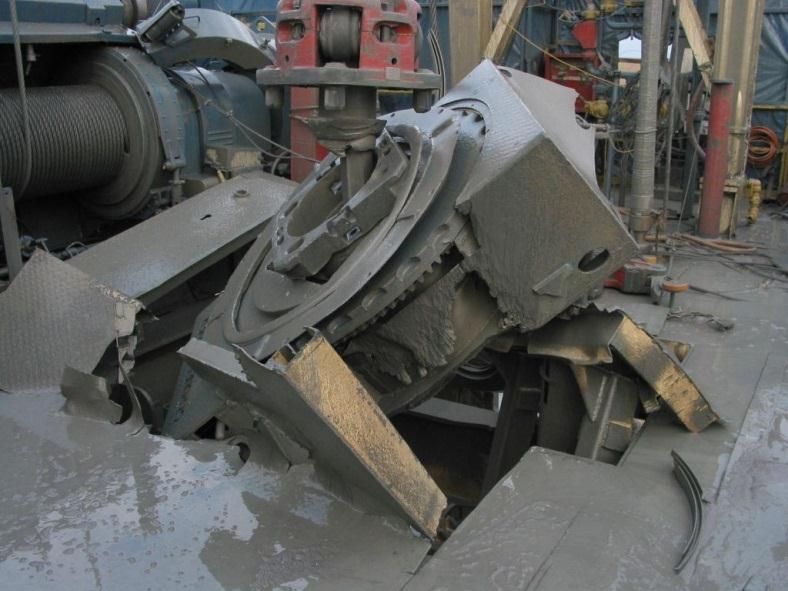
Setting the Packer
• Chances of setting packers go up sharply
  when a casing scraper is run. (Remember
  the burrs on the perforations?)

• The quantity of debris turned loose from the
  casing wall is often severe! (Tens of
  pounds worth!) Watch the formation
  damage.
Packer Set Point Requirements
•   Avoid setting packer in the      •   Remove burrs from pipe
    same joint where previous            above packer set point
    packers have been set.           •   Remove debris (dope, mill
•   Avoid doglegs, fault                 scale, mud, cement, etc.) on
    locations or high earth stress       casing wall (fills slip teeth)
    zones                            •   Well pressures are within
•   Adequate cement and bond             range of packer at set point
    required behind pipe at          •   Pipe alloy compatible with
    packer set point                     setting slips (hardness of
•   Caliper casing above and             casing relative to packer
    through the packer set point         slips)
•   Clearance between packer         •   Slip design & contact area
    and casing at set point is           acceptable for slip holding
    within rated range of packer     •   Weight applied to packer
•   Avoid zones of high                  can be transferred to
    corrosion, either internal or        formation
    external.
Information Required Before
Setting Packer or Plug
• Wellbore drawing with all diameters
• Last TD tag – rerun?
• Doglegs and deviations
• Viscosity of fluid in wellbore
– Calculate running speed vs. surge/swab.
• Copy of reference logs
• Where have other packers been set (avoid that joint)
• Set point requirements
• How can it be equalized if it has to be pulled?Job Checks • Measurements from CCL to a packer reference point. • Run in hole at about 100 fpm, slowing at ID restrictions. • Using CCL/GR, log up and correlate depths • Set packer – look for line weight reduction • Disconnect and log up a few collars (may be slightly off depth after disconnecting).
Job Checks
• Drop back and gently tag packer with
  setting tool to confirm depth.
• Log back up a few collars.
Packer Setting Guidelines
• Drift
• Scraping
• Casing Support
Drift the Casing
• Casing ID requirements above the set point
• Casing ID requirements below the set point
• Check the drift to deepest point with drift of
  diameter and length of packer.
Clean/Scrape The Casing?
• Removal of perforation burrs minimizes elastomer
  seal damage
• Removal of cement, mud, pipe dope and mill scale
  minimize debris that can fill the slips.
• Scraping casing can increase packer setting
  success
• Scraping casing can also produce some severe
  formation damage if perforations are not
  protected.
Casing Scraper – Designed to
knock off perforation burrs,
lips in tubing pins, cement
and mud sheaths, scale, etc.
It cleans the pipe before
setting a packer or plug.
The debris it turns loose from
the pipe may damage the
formation unless the pay is
protected by a LCM or plug.
One very detrimental action was running a scraper prior to packer
setting. The scraping and surging drives debris into unprotected
perfs.

                        Effect of Scraping or Milling Adjacent to Open
                                         Perforations

                  20    Perfs not protected by
                  10    LCM prior to scraping
                   0
 % Change in PI

                                      1                 Perfs protected
                                                                  2     by
                  -10
                                                        LCM
                  -20
                  -30
                                                 Short Term PI Change
                  -40
                                                 Long Term PI Change
                  -50
                  -60                                                    SPE 26042
Typical Completions • Single and Dual Zone Completion Types
Single Zone Completion
                    (Mechanical Packer)
                    Packer isolates casing from production
                    • Provides means of well control
                    • Protects casing above packer from corrosion
                    • Anchors tubing string
              On-Off Sealing Connector
                                         •   Tension Set
                                         •   Compression set
              Retrievable Packer         •   Wireline Set
                                         •   Large Variety of
                                             accessories available

Weatherford
Single Zone Completion
(Hydraulic Set Packer)
• Permits Packer setting without tubing
manipulation
–Common in offshore applications where SCSSV
control lines prevent tubing rotation
Flow Coupling
Sliding Sleeve
• Allows one-trip installation
Flow Coupling
• With sliding sleeve, allows packer fluid change-
Hydrostatic Retrievable Packer out after wellhead is flanged (sliding sleeve not
Flow Coupling
recommended in every case).
Seating Nipple
Spacer Tube
• Requires tubing plugging device to set packer
Ball Activated Pressure Sub –Wireline plug - preferred
Perforated Spacer Tube
No-Go Seating Nipple –Drop Ball Seat – debris problem?
Wireline Re-Entry Guide
WeatherfordSingle Zone Completion
(Seal Bore Packers)
• Dependable
• Low failure frequency
• Generally permit larger flow ID’s
Annulus Activated, Block and Kill Valve
• Available as Permanent or Retrievable
Sliding Sleeve
• Production string may be anchored or floating,
depending on tubing movement requirements
Seal Bore Packer (anchored or shouldered is highly recommended)
Mill-Out Extension
• Packer may be plugged, can be used as temporary
Crossover Sub
or permanent bridge plug
Flow Coupling
Seating Nipple
• Permanent packers removed by milling operations
Spacer Tube • Retrievable Seal Bore Packers are removed in
Flow Coupling
separate trip with retrieval tool – provided seals
No-Go Seating Nipple
Perforated Spacer Tube will release.
Crossover Sub
Seating Nipple
Wireline Re-Entry Guide
WeatherfordSingle Zone Completion
(Seal Bore Packers w/Locator Seal Assy.)
Sliding Sleeve
Flow Coupling
Locator Seal Assembly
• Locator unit atop Seal Bore Extension allows tubing
Seal Bore Packer movement from press and temp changes:
Seal Spacer Tube
– Frac or Acid Stimulation
Seal Bore Extension – Production extremes and shut-in
Tubing Seal Nipples
• Seals available to match environment:
Production Tube
– Temperature Range
Spacer Tube
– Pressure Conditions
Flow Coupling
Seating Nipple
– Fluid Environment
Perforated Spacer Tube
• Works well with tubing conveyed
No-Go Seating Nipple perforating (TCP)
WeatherfordSingle Zone Completion
(Polished Bore Receptacle (PBR))
• Seal Bore Packer with large upper
bore permits maximum flow area.
• PBR above packer accommodates
Locator Seal Assembly
tubing trip/movement
– Shear release locator allows one-trip
Retrievable Packer Bore Receptacle
installation with Hydraulic set packer
Anchor Tubing Seal Nipple
– Large ID suitable for Thru-Tubing
Hydraulic Set Seal Bore Packer
perforating
Mill-Out Extension
Crossover Sub
Shear-Out Ball Seat Sub
WeatherfordSingle Zone Completion
(Stacked Selective Completion)
Flow Coupling
Sliding Sleeve
• Permanent packers are stacked for
Seal Bore Packer
Seal Bore Extension
multiple zone completion
Tubing Seal Nipples
– Zones are selective flowed or shut-in by
Flow Coupling
Seating Nipple sliding sleeves or ported profiles and plugs
Blast Joint
Polished Nipple
– Tubing may be anchored or floating
Flow Coupling
Sliding Sleeve – Blast joints are placed across production
Seal Bore Packer
interval to reduce flow-cutting of
Seal Bore Extension production lines
Seal Spacer Tube
Tubing Seal Nipples
Spacer Tube • This type of completion design often has
No-Go Seating Nipple
Production Tube severe problems with leaking sleeves
Weatherford
and corroded/eroded tubing in the
straddled zone.Single Zone Completion
(Standard Dual Completion)
Flow Couplings
Seating Nipples
Flow Couplings
Flow Coupling
• Permits independent production of
Sliding Sleeve
Short String Seal Nipple
each zone
Dual Hydraulic Retrievable Packer
Flow Coupling
Seating Nipple
Flow Coupling
• Flanged-up completion for safety
Ball Activated Pressure Sub
Perforated Spacer Tube
No-Go Seating Nipple
Pinned Collar
• Fully retrievable completion (both
Seating Nipple
Blast Joint
packers) for remedial access
Polished Nipple
Sliding Sleeve
Hydraulic Retrievable Packer
• Or, the bottom packer may be a
Seating Nipple permanent packer which serves as
Ball Activated Pressure Sub
Perforated Spacer Tube
No-Go Seating Nipple
a locator for spacing out the
Wireline Re-Entry Guide
completion
WeatherfordYou can also read