PERFORMANCE EVALUATION OF A MOBILE MAPPING APPLICATION USING SMARTPHONES AND AUGMENTED REALITY FRAMEWORKS - ISPRS Annals of the Photogrammetry ...
←
→
Page content transcription
If your browser does not render page correctly, please read the page content below
ISPRS Annals of the Photogrammetry, Remote Sensing and Spatial Information Sciences, Volume V-2-2020, 2020
                                               XXIV ISPRS Congress (2020 edition)

      PERFORMANCE EVALUATION OF A MOBILE MAPPING APPLICATION USING
            SMARTPHONES AND AUGMENTED REALITY FRAMEWORKS

                                                    O. Hasler *, S. Blaser, S. Nebiker

        Institute of Geomatics Engineering, FHNW University of Applied Sciences and Arts Northwestern Switzerland, Muttenz,
                                 Switzerland – (oliver.hasler, stefan.blaser, stephan.nebiker)@fhnw.ch

                                                             Commission II

KEY WORDS: Augmented Reality, Outdoor, Smartphone, Mobile Mapping

ABSTRACT:

In this paper, we present a performance evaluation of our smartphone-based mobile mapping application based on an augmented
reality (AR) framework in demanding outdoor environments. The implementation runs on Android and iOS devices and
demonstrates the great potential of smartphone-based 3D mobile mapping. The application includes several functionalities such as
device tracking, coordinate, and distance measuring as well as capturing georeferenced imagery. We evaluated our prototype system
by comparing measured points from the tracked device with ground control points in an outdoor environment with four different
campaigns. The campaigns consisted of open and closed-loop trajectories and different ground surfaces such as grass, concrete and
gravel. Two campaigns passed a stairway in either direction. Our results show that the absolute 3D accuracy of device tracking with
state-of-the-art AR framework on a standard smartphone is around 1% of the travelled distance and that the local 3D accuracy
reaches sub-decimetre level.

                      1. INTRODUCTION                                  applications has been greatly simplified. These AR frameworks
                                                                       support device motion tracking and scene understanding.
The demand for capturing accurate 3D information is growing            Visually distinct features from the camera image – called
in a wide variety of indoor and outdoor disciplines such as BIM        feature points – combined with inertial measurements from the
(Building Information Modelling), facility management or               device’s IMU are used to calculate the device’s pose relative to
(indoor-) navigation. Until recently, environment mapping was          the environment. Clusters of feature points that lie on horizontal
a demanding task, requiring highly specialized multi-sensor            or vertical surfaces such as tables or walls are detected as planar
systems such as terrestrial or mobile laser scanners. Then, new        surfaces. Both ARCore and ARKit require mobile devices with
high quality portable mobile mapping systems (MMS) were                calibrated cameras and the generated point cloud is at world
introduced such as the BIMAGE backpack (Blaser et al., 2017).          scale.
With such a backpack, 3D point clouds and highly detailed 3D
image spaces (Nebiker et al., 2015) of construction sites,             At the Institute of Geomatics at the FHNW, we are developing a
tunnels, narrow streets or other areas inaccessible by a car-based     new AR mapping application, which shall combine the
MMS can be captured. However, when it comes to keeping the             advantages of the local tracking of an AR framework with
data up to date, using such high-end MMS would be too costly           referencing the device to a reference image dataset, which has
and the system would be restricted to a small group of experts.        been georeferenced in a geodetic reference system (Nebiker et
Hence, there should be a simple and cost-effective solution            al., 2015). As a first step, we developed an application, which is
allowing facility or infrastructure managers to keep the digital       able to motion track the device, measure points, localize itself to
twin of their site up to date.                                         a specific reference system and capture photographs with
                                                                       absolute orientation (Hasler et al., 2019). Once it is possible to
In recent years, the computing capacity of mobile devices has          align the captured photographs to a georeferenced image
rapidly increased, which is enabling more and more computing           database, this application is ready for various mapping tasks
intensive applications. A typical example is Augmented Reality         with high global accuracy. In our previous work we presented
(AR) applications, which are very demanding with respect to            our application and conducted accuracy experiments in indoor
scene tracking and augmentation in real-time – tasks which             environments. Now, we expand these accuracy experiments
were not possible on mobile devices a decade ago. Since                towards outdoor areas.
Niantic has released Pokémon Go in 2016, the number of AR
applications is rapidly increasing. Although Pokémon Go was a          Our paper is structured as follows: in chapter 2, we discuss the
geospatial AR application, the most common AR applications             related work. In chapter 3, we describe our development and
are placing virtual 3D objects in an arbitrary scene using either      architecture and in chapter 4 and 5, we outline our accuracy
a smartphone or AR glasses. These 3D objects can be as simple          experiments and their results. Finally, in chapter 6 we give a
as a toy figure or as complex as a scaled 3D city model. Most          conclusion and an outlook to future developments.
often, these AR applications are restricted to work only in a
single room or a small area.                                                               2. RELATED WORK

With the introduction of the AR frameworks ARCore (Google,             There are different types of mapping systems. On the one hand,
2019) and ARKit (Apple Developers, 2019), developing AR                there are static mapping systems like terrestrial laser scanners,

*   Corresponding author

           This contribution has been peer-reviewed. The double-blind peer-review was conducted on the basis of the full paper.
                       https://doi.org/10.5194/isprs-annals-V-2-2020-741-2020 | © Authors 2020. CC BY 4.0 License.                    741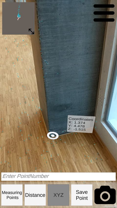
ISPRS Annals of the Photogrammetry, Remote Sensing and Spatial Information Sciences, Volume V-2-2020, 2020
                                             XXIV ISPRS Congress (2020 edition)

which scan the environment with high precision at the cost of a      outdoor environments and does not require ground control
time-consuming data collection process. On the other hand,           points. However, the success of this method depends on ideal
mobile mapping systems (MMS) are becoming more popular               conditions such as up-to-date reference images, same lighting,
since the data collection can be performed while driving or          seasonality and similar viewpoint. Since then, new and more
walking through the environment. Different MMS have been             robust methods have evolved. DenseSFM proposes a Structure
proposed, which can be categorized either by the platform type       from Motion (SfM) pipeline that uses dense CNN features with
or by the sensors used. Generally, there are backpack-based          keypoint relocalization (Widya et al., 2018). Sarlin et al. (2019)
systems, handheld systems and trolley-based systems. The             also use learned descriptors to improve localization robustness
Würzburg backpack (Lauterbach et al., 2015), for example,            across large variations of appearance. These approaches are
consists of a 2D laser profiler and a Riegl VZ-400 laser scanner.    more robust than using classical local features like SIFT and its
The BIMAGE research backpack system by FHNW (Blaser et               variants and have the potential to solve the absolute image
al., 2018) combines two Velodyne VLP-16 scanners with a              orientation problem. However, these approaches are
multi-head panorama camera. Among the commercially                   computationally heavy and at the time of writing, only a few
available backpacks is the Leica Pegasus:Backpack. It uses two       approaches are computing in real-time. Therefore, we have not
Velodyne VLP-16 scanners for the SLAM algorithm and has              yet implemented one of these approaches in our AR mapping
five divergent rear-facing cameras which are primarily used for      framework.
visualisation and digitising (Leica Geosystems AG, 2017). Such
high-end backpack systems generate accurate 3D information,                            3. OUR ACHITECTURE
but they are typically expensive and relatively heavy to carry.
Handheld LiDAR-based MMS like the Zebedee (Bosse et al.,             In this chapter we briefly describe our AR application. Further
2012), are easier to carry even in longer mapping campaigns.         information can be found in Hasler et al. (2019). The main goals
The Zebedee combines a lightweight laser scanner and an IMU          of our development included: a simple operation on a broad
to generate 3D point cloud. Numerous comparable commercial           range of devices, a compatibility with the two most prominent
products such as Zeb Revo from GeoSLAM or Stencil from               mobile operating systems Android and iOS, and a real-time
Kaarta (Zhang, Singh, 2017) are available. Kaarta’s Stencil uses     capability. The minimal functionality should include the
a Velodyne VLP-16 scanner together with an IMU for point             possibility to interactively localize the device in an absolute
cloud generation. Wheel-based MMS like the NavVis 3D                 reference frame using control points, to perform point and
Mapping Trolley has multiple cameras and four laser scanners         distance measurements and to capture georeferenced images.
(NavVis, 2019). Trolleys like this can be equipped with many
sensors but are restricted to flat and obstacle-free ground          3.1 Underlying Frameworks
surfaces. These type of MMS can generate dense and accurate
3D information but geo-referencing is either done in post            Our development is based on the widely used game engine
processing or by measuring ground control points (Lehtola et         Unity. Unity provides a large number of packages, which can be
al., 2017).                                                          included into a project. Unity-based applications can be
                                                                     deployed to various operating systems. Our project is developed
For measuring and mapping with consumer devices, there are
                                                                     with Unity’s AR Foundation package, which includes built-in
several AR mapping tools already available. Lenherr, Blaser
                                                                     multi-platform support for AR applications (Unity, 2018). This
(2020) evaluated some of them in terms of functionality and
                                                                     makes it possible to develop an application, which can run
accuracy. Smartphone applications such as CamToPlan or
                                                                     either Google’s ARCore or Apple’s ARKit depending on the
Magicplan (Magicplan, 2019) allow users to map and create
                                                                     user’s device and operating system.
floorplans. However, there are only a few AR applications
which support absolute geo-referencing. One approach to
                                                                     3.2 Implemented Functionality
overcome the absolute pose estimation problem is attaching a
highly accurate GNSS receiver to the smartphone. Schall et al.
(2009) combine a RTK receiver with an ultra-mobile PC and
sensor fuse it with inertial measurements and a visual
orientation tracker. One commercially available product is
Trimble SiteVision (Trimble, 2019). This system uses a GNSS-
receiver attached to a smartphone to receive centimetre-level
position accuracy. The orientation of the device is then
calculated from the travelled trajectory combined with a visual
tracking. Another way to solve the absolute geo-referencing
problem is presented by Christen et al. (2020). They compare a
local orthophoto produced by the mobile application with a
cadastral map or a global orthophoto as a reference. These
approaches rely either on a GNSS signal or on an available
orthophoto and therefore work only outdoors.
Precise automatic absolute geo-referencing, regardless of the
environment, is of great interest for numerous applications.
Visual Localization is a promising automatic geo-referencing
approach with intense research activity. Sattler et al. (2018)
distinguish the following visual localization categories: 3D
structure-based, 2D image-based, sequence-based and learning-        Figure 1. AR application: Measuring functionalities (left:
based localization. In our previous work, we introduced a            distance, right left: point measurement)
method for visual localization and pose estimation of a single
image to georeferenced RGB-D images (Nebiker et al., 2015;
Rettenmund et al., 2018). This method works in indoor and

         This contribution has been peer-reviewed. The double-blind peer-review was conducted on the basis of the full paper.
                     https://doi.org/10.5194/isprs-annals-V-2-2020-741-2020 | © Authors 2020. CC BY 4.0 License.                   742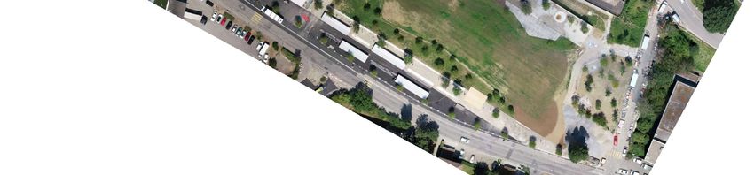
ISPRS Annals of the Photogrammetry, Remote Sensing and Spatial Information Sciences, Volume V-2-2020, 2020
XXIV ISPRS Congress (2020 edition)
3.2.3 Global Referencing: For absolute geo-referencing of
captured images and for conducting measurements in a global
reference frame, the device needs to be related to a reference
frame. For a first version, we realized a 6 degree of freedom
(6DoF) transformation using ground control points (GCPs) in
order to transfer the local scene into a global reference frame.
To start the referencing process, a list of GCPs can be imported
from file. After a successful import, at least three points need to
be measured with the AR app and referenced to a GCP by
choosing from a dropdown list. Again, measurements can be
directly conducted on feature points or on detected planar
surfaces. Then, the 6DoF transformation is calculated according
to Umeyama (1991) and the residuals are displayed (Figure 2
left). The transformation can easily be evaluated based on
residuals and dynamically adjusted by additional point
measurements or by the exclusion of points. Once the
transformation calculation is correct, any object in the global
reference system can be augmented in the camera feed of the
app. For verification purposes, the app overlays the GCPs into
Figure 2. AR application: Display of 6DoF transformation the camera feed.
residuals (left) and photo display with original pose (right,
captured photo in dashed rectangle) 3.2.4 Photo Capture with Pose: Finally, it is possible to
capture geo-referenced images. Every time a user takes a photo,
the app stores the local pose and if available the global pose
3.2.1 Device Tracking: The foundation of our application is (position and orientation). With the app, it is also possible to
the device tracking. The underlying AR frameworks support upload the photo with its pose to a web service. For verification
motion tracking by fusing multiple sensors such as purposes, the captured photograph can be displayed in the AR
accelerometer, gyroscope, magnetometer and camera. Visually scene at its real location and with its original pose (Figure 2
distinct feature points from the camera image combined with right).
inertial measurements are used to estimate the device’s relative
pose to the environment. Furthermore, the framework estimates 4. PERFORMANCE EVALUATION
horizontal and vertical planes with detected feature points,
which are mostly located on walls and on the floor. We carried out accuracy evaluations based on 3D point
measurements in order to determine the performance and
Once the AR app is started, device tracking starts immediately. stability of motion tracking and the subsequent measuring and
The origin of the local AR reference frame coincides with the mapping accuracy in outdoor environments.
location where the app was initialised – with the heading of the
device defining the direction of the forward axis, the up-axis In the following experiments, we investigate the deviations
pointing vertical and the right axis perpendicular to the right. along four trajectories in the park of the FHNW campus in
Muttenz near Basel (CMU). In the first case, the trajectory
Since either Google’s ARCore or Apple’s ARKit only run on forms a loop with identical start and destination points and in
calibrated devices and multiple sensors are fused, the AR the other three cases, the trajectory describes a route with
reference frame is automatically at world scale. different start and destination points. We then compare the
results with the achieved accuracies in the indoor environment.
3.2.2 Measurement Functionality: After the AR app has In all the following experiments, we used common high-end
been initialised, local measurements can be taken immediately. smartphones such as Google Pixel 2 and Samsung Galaxy S9.
The app supports two measurement modes: point and 3D
distance measurements (Figure 1). Other modes such as area, 4.1 Test Site
volumetric or slope measurements could additionally be
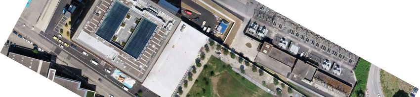
implemented. Both point and distance measurements can either Our test site is located in the park of the new FHNW Campus in
be made directly using individual feature points from the device Muttenz/Basel (Figure 3). The site has an extension of roughly
tracking or using the detected planar surfaces. Measuring on 70 x 150 meters and consists of different ground surfaces such
detected planar surfaces has the advantage that measurements as gravel, bitumen and grass. Most of the terrain is almost flat
can be carried out continuously, even when a surface is lacking and on the same altitude except for an embankment with a
visual features. stairway in the east of the park. The height difference of the
stairway is roughly 5 meters.
To execute a measurement, a single tap on the screen at the
desired location is required. Depending on the measuring mode, As a reference, we established 46 ground control points (GCPs)
a pop-up window with the local or global coordinates or the 3D which we measured with a GNSS rover Leica GS14 in RTK
distance appears. A 2D distance measurement mode (top down, mode. The overall accuracy of the reference system is < 3 cm.
floorplan) could be implemented additionally, if needed. The The GCPs are exactly defined natural points like manhole
coordinates of measured points can be saved to a text file with covers, traffic markings and intersections between different
local and if available global coordinates for further processing. ground surfaces.
This contribution has been peer-reviewed. The double-blind peer-review was conducted on the basis of the full paper.
https://doi.org/10.5194/isprs-annals-V-2-2020-741-2020 | © Authors 2020. CC BY 4.0 License. 743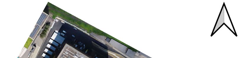
ISPRS Annals of the Photogrammetry, Remote Sensing and Spatial Information Sciences, Volume V-2-2020, 2020
                                             XXIV ISPRS Congress (2020 edition)

                                                                     the other campaigns, we measured the GCPs in the end at the
                                                                     bottom of the stairs.

                                                                     4.2.3 Stairs Up and Down: The third mapping experiment is
                                                                     similar to the second experiment but in reverse order. We
                                                                     started at the bottom of the stair, where we measured 13 GCPs.
                                                                     We then measured seven points along the stair and on top of the
                                                                     stair before descending again and measuring 10 additional
                                                                     points while heading towards the main building. This trajectory
                                                                     is in total 260 meters long with 30 measured points.

                                                                     4.2.4 Half loop: The last experiment starts at the same
                                                                     position as the first and ends at the bottom of the stairway. We
                                                                     measured 5 GCPs at the beginning and then 12 CPs along the
                                                                     220-meter trajectory.

                                                                                              5. RESULTS

Figure 3. Campus Muttenz with the main building (north-west)         In this chapter, we show and discuss the results of our four
       and its park (from the centre towards south-east)             trajectory investigations and compare them to our earlier indoor
                                                                     accuracy investigation (Hasler et al. 2019). First, we examined
4.2 Trajectories                                                     the tracking quality with statistical analyses from 3D
                                                                     measurements along the four different trajectories, one open and
On this site we conducted experiments with four different            the other three closed. Secondly, we compare the tracking
trajectories with lengths between 114 and 350 meters (Figure 4).     quality between outdoor and indoor environments.

                                                                     5.1 Trajectories

                                                                     The accuracy of the trajectories was assessed by comparing the
                                                                     measured check point coordinates along the mapping paths with
                                                                     their reference coordinates. Table 1 lists the RMSE values of all
                                                                     four trajectories for a) GCPs used for calculating the
                                                                     transformation only and b) CPs. Table 2 lists the maximum
                                                                     errors in respect to the travelled distance.

                                                                                             RMSE GCP [cm]         RMSE CP [cm]
                                                                      Trajectory             X    Y     Z          X   Y      Z
                                                                      1. Full loop           19     17      1     153     83    178
                                                                      2. Stairs down          7      2      1      81     12     16
            Figure 4. Different Trajectories at CMU                   3. Stairs up/down      15     15      4     228     54     53
4.2.1 Full loop: In the first of the four mapping experiments,        4. CMU->Stairs      21     14       2      274 173         78
we measured a trajectory, which forms a closed loop. In this                  Table 1. Residuals of the four trajectories
campaign, we measured 20 points in total. At the beginning, we
measured five GCPs and we additionally measured 15 check             The RMSE in both horizontal and vertical direction are
points (CP) along the loop. The trajectory length is about 350       surprisingly small considering the travelled distances in the
meters and first covers concrete surfaces and then gravel, grass,    range of 114 meters to 350 meters. Table 2 indicates the
and finally again concrete. The height difference of this track is   maximum error in each direction with respect to the travelled
less than 1 meter. The transformation parameters to the global       distance (both absolute in meters and relative to the total
reference frame were derived using the five GCP measurements         trajectory length). The maximum horizontal error of all
at the beginning of the trajectory. Once the transformation          campaigns is 3.9 meters after 258 meters along the trajectory in
parameters were estimated, all measured points were                  campaign number 3. The maximum vertical error is 2.2 meters
transformed into the global reference frame and the residuals to     after 282 meters in campaign number 1.
the GCPs were calculated.

4.2.2 Stairs Down: In the second mapping experiment, we
measured a 114-meter trajectory, which follows a stairway
downwards with different start and destination positions. After
measuring three points at the beginning, we measured four
points along the stairway (one at the top, two in the middle and
one at the bottom). We then measured eight additional points
below the stairs before finally measuring five GCPs. In total we
measured 20 points. We again used the GCPs to calculate the
transformation from the local to the global reference frame and
then transformed all points with these parameters. Finally, the
residuals were calculated for all measured points. In contrast to

         This contribution has been peer-reviewed. The double-blind peer-review was conducted on the basis of the full paper.
                     https://doi.org/10.5194/isprs-annals-V-2-2020-741-2020 | © Authors 2020. CC BY 4.0 License.                  744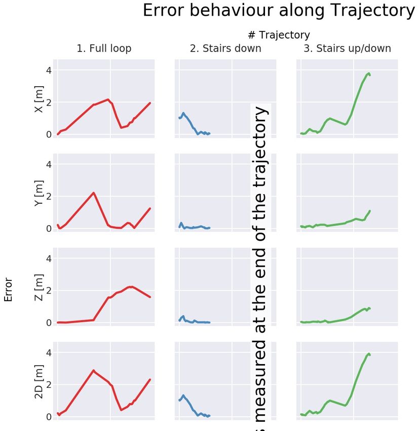
ISPRS Annals of the Photogrammetry, Remote Sensing and Spatial Information Sciences, Volume V-2-2020, 2020
                                              XXIV ISPRS Congress (2020 edition)

                                                                        however the GCPs of this trajectory are measured at the end and
             Max. error [cm] (travelled Distance [m] and in             therefore the errors decrease the closer the points are to the end
             % of total trajectory length)                              of the trajectory. In the third trajectory, the X component of the
Trajectory      X           Y          Z      2D         3D             position error starts to rapidly increase after roughly 180 meters.
              -217         222        223     289        289            This increase happened after the stairway was passed upward
1. Full       (191        (136       (282    (136       (136            and downwards and the device probably started to drift away in
loop           m,          m,         m,      m,         m,             the direction of walking.
             54 %)       39 %)      81 %)   39 %)      39 %)
                                                                        The vertical error in both the second and third trajectory is small
               133         35        - 40     133        139            regarding the vertical extent of both trajectories. The maximum
2. Stairs
             (15 m,      (7 m,     (15 m, (15 m, (15 m,                 vertical error of the second trajectory is only 40 cm and of the
down
             13 %)       6 %)       13 %)   13 %)      13 %)            third trajectory it is 90 cm at the very end but only 32 cm after
               380         110        91      393        403            going the stairway up and down again. The maximum vertical
3. Stairs     (258        (261       (258    (258       (258            error at the top of the stairway after going up was 18 cm
up/down        m,          m,         m,      m,         m,             (Trajectory 3).
             99 %) 100 %) 99 %)             99 %)      99 %)
              -391         244        143     420        444            The error in the X dimension of the fourth trajectory steadily
4. CMU-       (227        (160       (227    (227       (227            increases along the travelled path whereas the y-error remains
>Stairs        m,          m,         m,      m,         m,             low at the beginning and then starts to rapidly increase. The
             100 %) 71 %) 100 %) 100 %) 100 %)                          vertical error is again smaller than both errors in the horizontal
Table 2. Maximum errors with respect to the travelled distance          dimension.

                                                                        5.2 Comparison with indoor results

                                                                        When comparing our outdoor results to the indoor mapping
                                                                        campaign (Hasler et al., 2019), the 3D RMSE of the GCP
                                                                        measurements and of the overall measurements have increased
                                                                        (Table 3). Only the second outdoor campaign (stairway down)
                                                                        achieved similar accuracies. The maximum horizontal error in
                                                                        the indoor campaign was 1.6% of the total distance. In our
                                                                        outdoor experiments, we achieved a maximum horizontal error
                                                                        between 0.2% and 1.5% of the total distance.
                                                                        In contrast to the indoor mapping campaign, neither a rapid
                                                                        vertical shift nor a loop closure was detected during all four
                                                                        outdoor campaigns. In the first outdoor campaign, the AR
                                                                        device did not recognize its final location as the initial location
                                                                        and therefore did not perform a relocalization. The reason no
                                                                        rapid vertical shift happened is probably that there were no
                                                                        repetitive structures along the trajectory. Even the gravel
                                                                        surface provided enough unique features.

                                                                        Approach        3D error GCPs         3D error GCPs + CPs
                                                                                              [cm]                    [cm]
                                                                        Indoor 1              12.4                   107.8
                                                                        Indoor 2               4.9                    97.5
                                                                        Outdoor 1             25.5                   222.9
Figure 5. Behaviour of the absolute errors along the trajectories
                                                                        Outdoor 2              7.3                    71.9
As can be seen in Figure 5, drifts increase with the distance           Outdoor 3             21.6                   181.5
travelled from the start location. The 2D error of the first            Outdoor 4             25.3                   270.7
trajectory (full loop) first increases but after 136 meters starts to      Table 3. comparison of RMSE in GCP between indoor and
decrease again until around 240 meters and then starts to                                     outdoor campaigns
increase again. This phenomenon is only present in the first
trajectory. All errors of the second trajectory seem to decrease,

         This contribution has been peer-reviewed. The double-blind peer-review was conducted on the basis of the full paper.
                     https://doi.org/10.5194/isprs-annals-V-2-2020-741-2020 | © Authors 2020. CC BY 4.0 License.                       745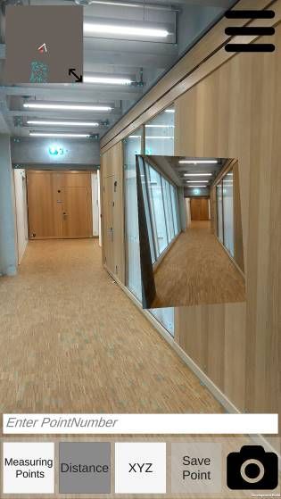
ISPRS Annals of the Photogrammetry, Remote Sensing and Spatial Information Sciences, Volume V-2-2020, 2020
                                             XXIV ISPRS Congress (2020 edition)

                                                       Figure 6. 2D and vertical error
             (top left: trajectory one, top right: trajectory two, bottom left: trajectory three, bottom right trajectory four)

            6. CONCLUSION AND OUTLOOK
                                                                        In the future, AR mapping apps could provide a low-cost front-
                                                                        end to an ecosystem of image-based mobile mapping and visual
We carried out performance investigations in a challenging              localization services. As demonstrated in this paper, consumer
outdoor environment without manmade structures with four                devices could be used for carrying out relatively accurate 3D
different campaigns. The four different trajectories covered            measurements and for updating existing image-based infra-
different surface types and even included vertical displacements        structure services, e.g. by providing accurately georeferenced
following a stairway. In our mapping test campaigns, we                 fault or change reports to facility managers.
showed that AR tools are surprisingly accurate with a max 3D
error of the full loop campaign of 2.89 m or 0.6% over a                Future work includes the combination of the high local accuracy
distance of 350 meters in a very demanding environment                  of an AR tool with GNSS or a visual positioning service as an
(Figure 5, left). The analysis of the difference vectors in Figure      absolute positioning system.
6 and the RMSE of the GCP measurements indicates that the
local accuracy is even higher. All this shows that AR tools have                           ACKNOWLEDGEMENTS
a huge potential in accurately tracking mobile devices in
outdoor environments without specific and expensive hardware.           The applied research project cloudIO (No. 32411.1 IP-ICT) was
                                                                        supported by Innosuisse, the Swiss Innovation Agency and by
In summary, we demonstrated that AR Frameworks are an                   our industry partner iNovitas AG.
interesting alternative to costly high-end mobile mapping
systems in certain application areas.

         This contribution has been peer-reviewed. The double-blind peer-review was conducted on the basis of the full paper.
                     https://doi.org/10.5194/isprs-annals-V-2-2020-741-2020 | © Authors 2020. CC BY 4.0 License.                   746
ISPRS Annals of the Photogrammetry, Remote Sensing and Spatial Information Sciences, Volume V-2-2020, 2020
                                            XXIV ISPRS Congress (2020 edition)

                      REFERENCES
                                                                    Rettenmund, D., Fehr, M., Cavegn, S., Nebiker, S., 2018.
Apple Developers, 2019. Augmented Reality – Apple Develop-          Accurate Visual Localization in Outdoor and Indoor Environ-
er. developer.apple.com/augmented-reality/ (16 October 2019)        ments Exploiting 3D Image Spaces as Spatial Reference. Int.
                                                                    Arch. Photogramm. Remote Sens. Spatial Inf. Sci., XLII-1, 355–
Blaser, S., Cavegn, S., Nebiker, S., 2018. Development of a         362. doi.org/10.5194/isprs-archives-XLII-1-355-2018
Portable High Performance Mobile Mapping System Using the
Robot Operating System. ISPRS Ann. Photogramm. Remote               Sarlin, P.-E., Cadena, C., Siegwart, R., Dymczyk, M., 2019.
Sens. Spatial Inf. Sci., IV-I, 13–20. doi.org/10.5194/isprs-        From Coarse to Fine: Robust Hierarchical Localization at Large
annals-IV-1-13-2018                                                 Scale. CoRR, abs/1812.03506. arxiv.org/abs/1812.03506

Blaser, S., Nebiker, S., Cavegn, S., 2017. System Design,           Sattler, T., Maddern, W., Toft, C., Torii, A., Hammarstrand, L.,
Calibration and Performance Analysis of a Novel 360° Stereo         Stenborg, E., Safari, D., Masatoshi, O., Pollefeys, M., Sivic, J.,
Panoramic Mobile Mapping System. ISPRS Ann. Photogramm.             Kahl, F., Pajdla, T., 2018. Benchmarking 6DOF Outdoor Visual
Remote Sens. Spatial Inf. Sci., IV-1/W1, 207–213.                   Localization in Changing Conditions. IEEE/CVF Conference on
doi.org/10.5194/isprs-annals-IV-1-W1-207-2017                       Computer Vision and Pattern Recognition (CVPR), Salt Lake
                                                                    City, UT, 2018, 8601–8610.
Bosse, M., Zlot, R., Flick, P., 2012. Zebedee: Design of a          doi.org/10.1109/CVPR.2018.00897
spring-mounted 3-D range sensor with application to mobile
mapping. IEEE Transactions on Robotics, 28(5), 1104–1119.           Schall, G., Wagner, D., Reitmayr, G., Taichmann, E., Wieser,
doi.org/10.1109/TRO.2012.2200990                                    M., Schmalstieg, D., Hofmann-Wellenhof, B., 2009. Global
                                                                    pose estimation using multi-sensor fusion for outdoor
Christen, M., Schmid, S., Gasparik, M., Clement, U., 2020.          Augmented Reality. Proceedings of the 8th IEEE 2009
Outdoor Augmented Reality for Underground Infrastructure of         International Symposium on Mixed and Augmented Reality
Urban Areas. Int. Arch. Photogramm. Remote Sens. Spatial Inf.       (ISMAR), 153–162. doi.org/10.1109/ISMAR.2009.5336489
Sci., Nice, France.
                                                                    Trimble, 2019. Trimble SiteVision – Outdoor Augmented
Google, 2019. ARCore – Google Developers.                           Reality System. sitevision.trimble.com (30 October 2019)
developers.google.com/ar (16 October 2019)
                                                                    Umeyama, S., 1991. Least-Squares Estimation of Transforma-
Hasler, O., Blaser, S., Nebiker, S., 2019. Implementation and       tion Parameters Between Two Point Patterns. IEEE Trans-
First Evaluation of an Indoor Mapping Application Using             actions on Pattern Analysis and Machine Intelligence, 13(4),
Smartphones and AR Frameworks. Int. Arch. Photogramm.               376–380. doi.org/10.1109/34.88573
Remote Sens. Spatial Inf. Sci., XLII-2/W17, 135–141.
doi.org/10.5194/isprs-archives-XLII-2-W17-135-2019                  Unity, 2018. About AR Foundation. docs.unity3d.com/
                                                                    Packages/com.unity.xr.arfoundation@2.2/manual/index.html
Lauterbach, H. A., Borrmann, D., Heß, R., Eck, D., Schilling,       (16 October 2019)
K., Nüchter, A., 2015. Evaluation of a Backpack-Mounted 3D
Mobile Scanning System. Remote Sensing, 7(10), 13753–               Widya, A. R., Torii, A., Okutomi, M., 2018. Structure-from-
13781. doi.org/10.3390/rs71013753                                   Motion using Dense CNN Features with Keypoint Relocaliza-
                                                                    tion. CoRR, abs/1805.03879. arxiv.org/abs/1805.01879
Lehtola, V. V., Kaartinen, H., Nüchter, A., Kaijaluoto, R.,
Kukko, A., Litkey, P., Honkavaara, E., Rosnell, T., Vaaja, M.       Zhang, J., Singh, S., 2017. Low-drift and real-time lidar
T., Virtanen, J-P., Kurkela, M., Issaoui, A. El, Zhu, L.,           odometry and mapping. Autonomous Robots, 41(2), 401–416.
Jaakkola, A., Hyyppä, J., 2017. Comparison of the Selected          doi.org/10.1007/s10514-016-9548-2
State-Of-The-Art 3D Indoor Scanning and Point Cloud
Generation    Methods.    Remote    Sensing,     9(8).   796.
doi.org/10.3390/rs9080796

Leica Geosystems AG., 2017. Leica Pegasus : Backpack Mobile
reality capture. leica-geosystems.com/products/mobile-sensor-
platforms/capture-platforms/leica-pegasus-backpack (30 April
2020)

Lenherr, P., Blaser, S., 2020. 3D-Vermessung mit Smartphone
Apps. Geomatik Schweiz, 1(4), 10–13.

Magicplan, 2019. Magicplan. The #1 Floor Plan App.
www.magicplan.app/en/ (30 October 2019)

NavVis, 2019. NavVis M6 Indoor Mobile Mapping System.
www.navvis.com/m6 (28 October 2019)

Nebiker, S., Cavegn, S., Loesch, B., 2015. Cloud-Based
Geospatial 3D Image Spaces—A Powerful Urban Model for the
Smart City. ISPRS Int. J. Geo-Information, 4(4), 2267–2291.
doi.org/10.3390/ijgi4042267

        This contribution has been peer-reviewed. The double-blind peer-review was conducted on the basis of the full paper.
                    https://doi.org/10.5194/isprs-annals-V-2-2020-741-2020 | © Authors 2020. CC BY 4.0 License.                   747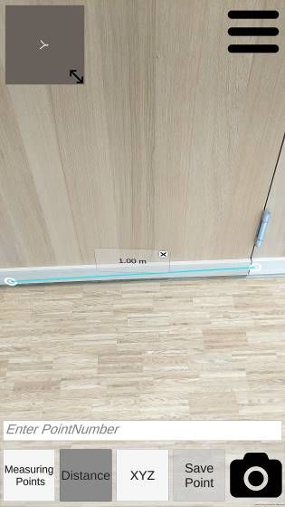
You can also read