Performance Validation of An Upper Limb Exoskeleton Using Joint ROM Signal
←
→
Page content transcription
If your browser does not render page correctly, please read the page content below

https://www.scientificarchives.com/journal/archives-of-orthopaedics

    Archives of Orthopaedics                                                                                     Research Article

Performance Validation of An Upper Limb Exoskeleton
Using Joint ROM Signal

Yousef Alshahrani1,4, Yang Zhou1, Chaoyang Chen1,2*, Hannah Joines2, Tangfei Tao3,
Guanghua Xu3, Stephen Lemos2
1
    Robotic Rehabilitation Laboratory, Department of Biomedical Engineering, Wayne State University, Detroit, Michigan, USA
2
    Department of Orthopaedic Surgery and Sports Medicine, Detroit Medical Center, Detroit, Michigan, USA
3
    The Scholl of Mechanical Engineering, Xian Jiaotong University, Xian, China
3
    Prosthetics and Orthotics Department, Taibah university, Saudi Arabia
*
    Correspondence should be addressed to Chaoyang Chen; cchen@wayne.edu
Received date: March 09, 2021, Accepted date: April 19, 2021

 Copyright: © 2021 Alshahrani Y, et al. This is an open-access article distributed under the terms of the Creative Commons
Attribution License, which permits unrestricted use, distribution, and reproduction in any medium, provided the original author
and source are credited.

Abstract
Exoskeleton systems are emerging for robotic assistive surgery and rehabilitation of neurologically impaired patients. A novel upper
extremity (UE) exoskeleton has been developed in our lab, potentially to be used for robotic assistive surgery and stroke rehabilitation
in our laboratory. The purpose of this study was to introduce the methodology of voluntary control of the UE exoskeleton by processing
the range of motion (ROM) of UE joints. Ipsilateral-to-ipsilateral synchronous (IIS) control and ipsilateral-to-contralateral mirror
(ICM) control mechanism were designed for UE exoskeleton movement control. A 3D simulation was performed to validate
mechanical designs for kinesiologic motion. The performance of the ROM-controlled UE exoskeleton was then validated among six
healthy subjects. The UE exoskeleton performed drawing movements in a 2D panel. The drawings created by the UE exoskeleton were
compared to the drawings created by a healthy subject to determine the accuracy of the drawing performance. Reliability statistical
analysis (Cronbach test) was performed to determine the inter-rater agreement between subject performance and UE exoskeleton
performance. Results showed an excellent agreement between the human drawings and exoskeleton drawings (Cronbach Alpha value
= 0.904, p
Alshahrani Y, Zhou Y, Chen C, Joines H, Tao T, Xu G, et al. Performance Validation of An Upper Limb Exoskeleton
Using Joint ROM Signal. Arch Orthop. 2021; 2(1): 20-30.

include consideration for routine tasks that are typically      the exoskeleton (Figure 1). Synchronous or mirror control
performed daily. Such tasks might involve synchronous           technique was used for precise movement control. A
or asynchronous movements; asynchronous movements               bilateral UE exoskeleton system was developed for this
could be bilateral or unilateral [7]. Bilateral training is     study. The joints of one exoskeleton arm were installed with
effective and involved in central nervous system (CNS)          angular decoders to detect the angles of the joints during
neuroplasticity. When movement is made with one limb,           motion. The obtained angular information was processed
the CNS activity that initiates that movement affects the       and encoded by a computer to control the movements
part of the CNS associated with the opposite limb [5].          of ipsilateral or contralateral exoskeleton movements.
Additionally, brain activity involved in the bilateral arm      This ipsilateral-for-contralateral mirror (ICM) control
and hand movements is not merely composed of the                technique was designed for stroke patients or orthopaedic
summation of the mechanisms of unilateral movements;            postoperative rehabilitation training, which uses healthy
specific neural control mechanisms that fire only during        arm joint motion information for affected arm motion
bimanual movements are engaged in the supplemental              control. While ipsilateral-to-ipsilateral synchronous (IIS)
motor cortex (SMA) and the primary motor cortex                 control technique can potentially be used for surgical
(M1) [8]. Making use of this concept is known as motor          robot movement control by surgeons.
control training. It has long been known in the field of
physiotherapy that training with bimanual movements is
beneficial for patients with hemiparesis. It is worth noting
that unilateral practice with the unaffected limb can be
effective in treating the affected limb, and for this reason,
this practice may be bilateral.

  Voluntary control of an upper arm exoskeleton involves
synchronous movements between the user and a robot at
user’s will. Researchers have developed newer upper limb
exoskeletons with promising outcomes for obtaining better
control accuracy for desired tasks. Several exoskeletons
with multiple degrees of freedom (DoF) of the human
arm have been developed, including the X-Arm 2 [9],
MGA Exoskeleton [10], ARMin [11], and VI-Bot [12].
However, the requirements for an assistive robotic system
for medical use are different from industrial applications.
A specialized approach in designing an exoskeleton for
rapid and precise positioning tasks is required. Current
limitations include range of motion, alignment, bulkiness,
weight, and cost.                                               Figure 1: Exoskeleton 3D Design.

  This paper presents a novel robot control mechanism,           The exoskeleton for the affected arm has motors in
which is named the mirror or synchronous motion control         addition to the encoders. User-initiated movements
strategy, along with strategies for fostering robotic systems   detected from the healthy arm were transferred to the
in clinical use. Ranges of motion (ROM) of multiple upper       exoskeleton for the affected arm motion control, resulting
arm joints are encoded and then decoded for the upper           in a synchronous movement of UE exoskeleton and healthy
arm exoskeleton movement control. The objective of the          subject arms. The encoders on the exoskeleton for the
study was to determine the effectiveness of processing          affected arm provided feedback on the angles to validate
ROM signals for exoskeleton control by evaluating the           that the angles between the two exoskeletons match.
performance of an exoskeleton based on 0peration
accuracy and precision of movements. The accuracy of             There were four-DoF motions of each arm exoskeleton.
the system performance was tested and validated among           Each DoF of motion was controlled by a stepper motor
healthy volunteers.                                             (Figures 1 and 2). Three stepper motors were used
                                                                by shoulder glenohumeral (GH) joint motion along
 Materials and Methods
                                                                horizontal (X), vertical (Y), and sagittal (Z) directions.
 Mechanical design                                              The elbow joint of the UE exoskeleton was designed with
                                                                one DoF of motion for flexion and extension. The motion
 Our upper arm system exoskeleton has four joints to            of exoskeleton shoulder joint at the Z axis was controlled
provide multiple degree of freedom (DoF) motions for            by Motor 1, which provides an actuation for adduction

Arch Orthop. 2021
Volume 2, Issue 1                                                                                                     21
Alshahrani Y, Zhou Y, Chen C, Joines H, Tao T, Xu G, et al. Performance Validation of An Upper Limb Exoskeleton
Using Joint ROM Signal. Arch Orthop. 2021; 2(1): 20-30.

Figure 2: Shows the UE exoskeleton with multiple DoF motions actuated by 4 stepper motors.

and abduction of the shoulder joint. Motor 2 provided             Control system
actuation for humerus internal and external rotations at
the Y axis. Motor 3 flexed and extended the exoskeleton           There are several actuation technologies reported
shoulder joint at the X axis. Motor 4 flexed and extended        previously [14], in our study, each joint of the exoskeleton
the elbow joint of the UE exoskeleton (Figure 2).                for the affected arm was installed a DC motor with a
                                                                 planetary gearbox having a gear ratio such as 263:1.
 Joint movement                                                  Position measurements were obtained using an encoder
                                                                 for closed-loop feedback of position information. This type
 Our UE exoskeleton is intended to assist in human               of encoder had high-resolution (600 pulses per revolution)
upper limb movements. There is a need for the axes of            with guaranteed high precision and a response frequency
the exoskeleton to be perfectly aligned to the human             of 20KHz (a period of 50 µs). Each motor is controlled by
joint axes [13]. There is a misalignment between the             a separate microprocessor (ARDUINO MEGA 2560 REV3,
joints of the exoskeleton and those of the human which           with a 16 MHz, 0.06 µs clock speed) and motor speed
can cause the generation of unwanted interaction forces          0.13sec/60 degree at 8.4V (Figure 3).
and mispositioning. To address this issue, the proposed
exoskeleton structure was designed to keep the shoulder           System validation and performance
and elbow joints aligned. Axis of motors 1, 2, and 3 (Figure
2) was aligned and met with the shoulder rotation center          Three dimensional (3D) simulations were used to
of rotation. The axis of motor 4 was aligned with the            determine any dynamic problems for different joint
elbow joint flexion/extension axis. The length of forearm        movements and to make necessary changes to mechanical
of the exoskeleton was adjustable during the motion thus         designs in simulations. Simulations were performed
avoiding the misalignment between the exoskeleton and            before the final mechanical design was set-up for the
user.                                                            prototype and human subject testing. The simulations

 Figure 3: Single joint control mechanism showing the flowchart of ROM signal processing for motor control.

Arch Orthop. 2021
Volume 2, Issue 1                                                                                                      22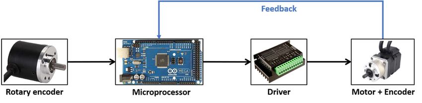
Alshahrani Y, Zhou Y, Chen C, Joines H, Tao T, Xu G, et al. Performance Validation of An Upper Limb Exoskeleton
Using Joint ROM Signal. Arch Orthop. 2021; 2(1): 20-30.

were done in SOLIDWORKS software using 3D human                dominant hand. The robot arm was placed in a parallel
models with moving joints to mimic the range of motion         position with the subject. The subject repeatedly drew a
in shoulder and elbow joints. The segments of the model        pattern, and the motorized exoskeleton performed the
were established based on lengths from the average male        same motion pattern (Figure 4). The results were analyzed
size. The software monitored whether the design could be       by tallying the distances between expected and actual
used to perform the full range of motion in the workspace.     locations drawn with motorized assistance.

 System validation and performance                                The drawing was performed on a vertical plane. The
                                                               pattern was a square-shape to allow for four different
 (1) Subject Requirement. This study was performed             movements [15]. The panel had four corners, each of which
in the Robotic Rehabilitation Lab, six healthy subjects        was 15 cm from the other point. The shoulder centers of
were recruited in study. They had no evidence or known         rotation of both the subject and the robot arm were aligned
history of skeletal or neurological disorders and displayed    with the centers of the square shapes. There was a pen
a normal range of motion and muscle upper-limb strength.       affixed to the hand of the subject and another to the robot
The study has been approved by the ethics committee            arm. The subject proceeded to draw from Corner 1 to each
(Institutional Review Board) of Wayne State University.        of the four targets, which included the movements from
                                                               Corner 1 to 2, 2 to 3, and 3 to 4. The subject drew from one
 (2) Study objectives and design. The exoskeleton mounted      target to the next until all four targets had been reached (1,
with ROM signal decoders was placed on the arm of the          2, 3, 4). The test was repeated three times (Figure 5).

 Figure 4: One subject performed two trails. The results were then compared using CA, MSE and SSIM methods.

Arch Orthop. 2021
Volume 2, Issue 1                                                                                                      23
Alshahrani Y, Zhou Y, Chen C, Joines H, Tao T, Xu G, et al. Performance Validation of An Upper Limb Exoskeleton
Using Joint ROM Signal. Arch Orthop. 2021; 2(1): 20-30.

                                                                index (SSIM) were used to measure the difference of
                                                                position points on the drawings between human and robot.
              1                              2                  SSIM is specifically used to quantify differences between
                                                                similar images. It was used in this study to incrementally
                                                                compare small segments (boxes containing both x and y
                                                                information) of the two images, with increments going in
                                                                both the x and y directions. The resulting index is the mean
                                                                value for the entire image.

                                                                 Statistical analysis

                                                                 Reliability test (Cronbach test) was used to determine
              4                              3                  the agreement between human and robot drawings.
                                                                Cronbach’s Alpha was measured to determine the extent of
                                                                inter-rater agreement between human and robot drawings.
 Figure 5: The direction of drawing a square route.             Statistical software SPSS (version 26, IBM, Armonk, NY)
                                                                was used for statistical analysis with p value smaller than
 The template for the square shape was on graph paper.          0.05 considered to be significant.
Figure 4 shows the direction of drawing movements. With
the healthy arm, the subject drew from Corner 1 to Corner       Results
2, and then made an angle to draw from Corner 2 to Corner
3. The associated drawing done by the robot arm was              Validation of mechanical design
used for comparison. The images were processed using
Python toolboxes (version 3.9.1) to define the percentage         A 4-DOF exoskeleton to support activities of daily
of the match. Repeated measures were used to compare            living ADL was reproduced (Figure 6) to determine the
the percentages of matching points. Both X and Y for            efficiency of processing joint ROM information for robot
each corner was compared to each x and y of the original        motion control. The exoskeleton enabled the shoulder and
drawing.                                                        the elbow 3-DoF and 1-DoF of movement respectively,
                                                                allowing the UE exoskeleton to accomplish a large range
 Mean squared error (MSE) and structural similarity             of motion by the wearer.

 Figure 6: 3D-printed 4-DOF Bilateral Upper-limb Exoskeleton.

Arch Orthop. 2021
Volume 2, Issue 1                                                                                                     24
Alshahrani Y, Zhou Y, Chen C, Joines H, Tao T, Xu G, et al. Performance Validation of An Upper Limb Exoskeleton
Using Joint ROM Signal. Arch Orthop. 2021; 2(1): 20-30.

 Range motion of UE exoskeleton                                       For the three methods used to validate the performance of
                                                                     the exoskeleton system: The Cronbach’s Alpha result was
 The UE exoskeleton moved within a 3D coordinate system              0.996 (reliability Cronbach test, p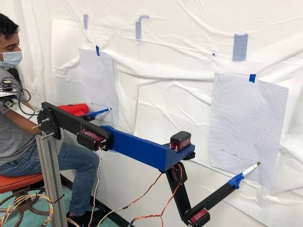
Alshahrani Y, Zhou Y, Chen C, Joines H, Tao T, Xu G, et al. Performance Validation of An Upper Limb Exoskeleton
Using Joint ROM Signal. Arch Orthop. 2021; 2(1): 20-30.

 94.67                                         99.94                                  1

 95.71                                         99.96                                  2                 3

 96.15                                         99.91                                  3

 93.82                                         99.94                                  1

 93.28                                         99.93                                  2                 4

 95.31                                         99.73                                  3

 91.92                                         99.92                                  1

 86.58                                         99.90                                  2                 5

 95.11                                         99.93                                  3

 95.31                                         99.95                                  1

 85.85                                         99.89                                  2                 6

 95.11                                         99.93                                  3

 90.49166667                                   99.80944444                            Average
Table 2: Drawing comparison results of MSE and SSIM Measures.

Discussion                                                      related metrics and healing progress record charts. In our
                                                                research, the ICM controlled exoskeleton was designed to
 In this paper, it is demonstrated that ROM signal of a         be used for rehabilitation training, the IIS (ipsilateral-to-
subject’s upper limb joints can be processed to precisely       ipsilateral synchronous) control mechanism was designed
control a wearable exoskeleton system. Potentially, it          to provide a control mechanism for a remote surgical
can be used for the voluntary control of a rehabilitative       robot. A surgeon may wear a ROM-control exoskeleton
exoskeleton or robotic assistive robots. This novel approach    to guide a remote robot to perform a surgery. Our study
generated a mechanism for using a robotic device with IIS       demonstrated that the IIS control mechanism accurately
or ICM control algorithms for UE exoskeleton movement           read the ROM of joints and synchronously control the
control.                                                        movement of a robot.

 Volitional-control robotic assistive rehabilitation             Research of human machine interface (HMI) is a hot
improved patient treatment outcomes [16-18]. Most of            topic recently. However, processing human motion intents
these studies used brain wave (electroencephalography,          for robot control still has significant challenges and is open
EEG) or electromyography (EMG) signals for voluntary            for further research [19]. Consequently, optimization and
control of exoskeletons or end effectors [16]. In this study,   selection of the best control method is a difficult task. The
ROM of UE joint was used for voluntary control of an            control methods for upper-limb exoskeleton robots are
UE exoskeleton. This ipsilateral-to-contralateral mirror        classified in several ways. They can be classified based
(ICM) control mechanism used the healthy arm ROM                on the types of input information, output information,
signals to control the affected arm exoskeleton for motion      or architecture of the controller [18]. The classification
assistance. Potential benefits of the bilateral exoskeleton     based on controller input signals is the most important
system include growing independence for patients. The           issue, as the input signals are critical to identifying the
device provides repeated and intensive physiotherapy            human motion. Control methods based on controller
sessions, thus reducing both the therapist’s burden and         input are categorized based on the input signals from
healthcare expense. Progress can be chart-recorded with         biological measurements, non-biological measurements,
ROM information output from the angular decoder. In             or platform-independent sources. Control methods
terms of orthopaedic applications, this device provides         based on biological signals can be obtained directly
measurements of many limb movements for kinematic               from a human, including electromyography (EMG) and
and dynamic parameters, thus providing performance-             electroencephalography (EEG) signals. Techniques have

Arch Orthop. 2021
Volume 2, Issue 1                                                                                                       26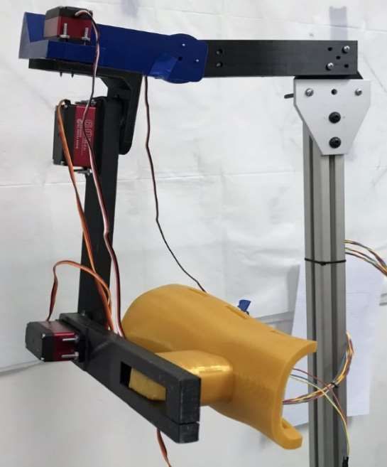
Alshahrani Y, Zhou Y, Chen C, Joines H, Tao T, Xu G, et al. Performance Validation of An Upper Limb Exoskeleton
Using Joint ROM Signal. Arch Orthop. 2021; 2(1): 20-30.

been developed to receive and interpret information              Our results indicated that the encoders read user’s joint
regarding user intention from non-biological signals as         angles accurately for UE exoskeleton motion control.
input to the control methods [20]. These control methods        Comparison of the accuracy of drawings was used for
identify human motion by using instrumentation to sense         system’s performance evaluation. The results showed a
the results of biological activity rather than the biological   good matching of drawing figures between human and
activity itself. Some examples of such instrumentations         robotic UE exoskeleton. This study demonstrated that
are torque/force sensors or dynamic modeling of the             decoding ROM signals for IIS or ICM control can be a
human limb. In platform-independent control methods,            feasible approach for research and product development
various control strategies are used with the exoskeleton        of medical robots for navigation surgery or rehabilitation.
developments. These control strategies are implemented          It may potentially be used for chart-record of healing
to improve the features and performance of the control          progress according to the digital output from the angular
systems in exoskeleton robots, but they make the systems        decoders.
complicated and large [21-23]. Force sensors make the
whole system both expensive and bulky. The ROM signals           Limitations of this study include that only healthy subjects
for UE exoskeleton control in this study demonstrated that      were studied for our current prototype development.
it is a reliable method for medical robot control.              Future studies include a clinical study using ROM-
                                                                controlled UE exoskeleton for orthopaedic post-operative
  Current available bilateral upper-limb exoskeletons have      UE rehabilitation and stroke rehabilitation trainings.
limited ranges of motion and are of little assistance to the    Robot assistive surgery and robotic rehabilitation in stroke
affected limb of the user. Such UE exoskeletons include         and post-orthopaedic surgery are emerging and pioneering
Bi-Manu-Track, Nudelholz, Tailwind, Reha-Slide Duo,             research topics in orthopedics, more studies are required
and The Rocker for APBT, Braccio di Ferro, and Batrac [7,       for further product development research.
13, 24, 25]. The control mechanisms of that exoskeleton
are not voluntary at user’s will. Our bilateral exoskeleton     Conclusion
uses encoders to read joint angles from the healthy side
and mirror those angles to the effected side. The encoder        In this paper, a novel four-DoF upper-limb exoskeleton
has high-resolution (600 pulses per revolution) with            was presented together with its motion control
guaranteed high precision, and the response frequency is        mechanisms. ROM signal of joints can be processed for the
up to 20KHz (a period of 50 µs). Each motor is controlled       motion control of paired UE exoskeleton system either for
by a separate microprocessor (ARDUINO MEGA 2560                 the ipsilateral or contralateral arm. The ROM controlled
REV3, which has a 16 MHz, 0.06 µs, clock speed) and             paired UE exoskeletons can potentially be used for clinical
motor speed 0.13sec/60 degree at 8.4V (Figure 8).               rehabilitation or navigation of a remote surgical robot.

 Figure 8: Diagram of the control system.

Arch Orthop. 2021
Volume 2, Issue 1                                                                                                      27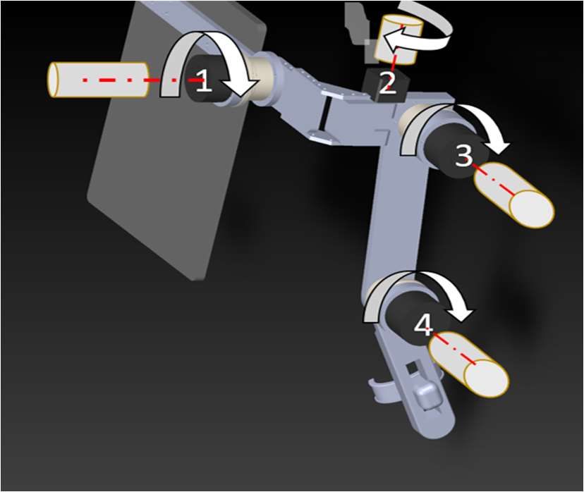
Alshahrani Y, Zhou Y, Chen C, Joines H, Tao T, Xu G, et al. Performance Validation of An Upper Limb Exoskeleton
Using Joint ROM Signal. Arch Orthop. 2021; 2(1): 20-30.

Disclosure Statement                                         In2009 IEEE/RSJ International Conference on Intelligent
                                                             Robots and Systems 2009 Oct 10 (pp. 3697-3702). IEEE.
 No potential conflict of interest was reported by the
authors.                                                      11. Nef T, Riener R. ARMin-design of a novel arm
                                                             rehabilitation robot. In9th International Conference on
Funding                                                      Rehabilitation Robotics, 2005. ICORR 2005. 2005 Jun 28
                                                             (pp. 57-60). IEEE.
 Wayne State University, UPTF Development Grant.
                                                              12. Mallwitz M, Benitez LV, Bongardt B, Will N. C
References                                                   PIOUBE.

 1. Gopura RA, Kiguchi K. Mechanical designs of active         13. Ericson A, Arndt A, Stark A, Wretenberg P, Lundberg
upper-limb exoskeleton robots: State-of-the-art and          A. Variation in the position and orientation of the elbow
design difficulties. In2009 IEEE International Conference    flexion axis. The Journal of Bone and Joint Surgery. British
on Rehabilitation Robotics 2009 Jun 23 (pp. 178-187).        Volume. 2003 May;85(4):538-44.
IEEE.
                                                              14. Letier P, Avraam M, Horodinca M, Schiele A, Preumont
  2. Maciejasz P, Eschweiler J, Gerlach-Hahn K, Jansen-      A. Survey of actuation technologies for body-grounded
Troy A, Leonhardt S. A survey on robotic devices for upper   exoskeletons. InProc. Eurohaptics 2006 Conference 2006
limb rehabilitation. Journal of Neuroengineering and         Jul (pp. 497-500).
Rehabilitation. 2014 Dec;11(1):1-29.
                                                              15. Nordin N, Xie SQ, Wünsche B. Assessment of movement
 3. Hessinger M, Müller R, Werthschützky R, Pott PP.         quality in robot-assisted upper limb rehabilitation after
Tool position control of an upper limb exoskeleton for       stroke: a review. Journal of Neuroengineering and
robot-assisted surgery. IFAC-PapersOnLine. 2015 Jan          Rehabilitation. 2014 Dec;11(1):1-23.
1;48(20):195-200. 4. Lang JE, Mannava S, Floyd AJ,
Goddard MS, Smith BP, Mofidi A, et al. Robotic systems        16. Baniqued PD, Stanyer EC, Awais M, Alazmani A,
in orthopaedic surgery. The Journal of Bone and Joint        Jackson AE, Mon-Williams MA, et al. Brain–computer
Surgery. British volume. 2011 Oct;93(10):1296-9.             interface robotics for hand rehabilitation after stroke:
                                                             a systematic review. Journal of NeuroEngineering and
 5. Whitall J, Waller SM, Silver KH, Macko RF. Repetitive    Rehabilitation. 2021 Dec;18(1):1-25.
bilateral arm training with rhythmic auditory cueing
improves motor function in chronic hemiparetic stroke.        17. Bundy DT, Souders L, Baranyai K, Leonard L,
Stroke. 2000 Oct;31(10):2390-5.                              Schalk G, Coker R, Moran DW, Huskey T, Leuthardt EC.
                                                             Contralesional brain–computer interface control of a
 6. Coupar F, Pollock A, Van Wijck F, Morris J, Langhorne    powered exoskeleton for motor recovery in chronic stroke
P. Simultaneous bilateral training for improving arm         survivors. Stroke. 2017 Jul;48(7):1908-15.
function after stroke. Cochrane Database of Systematic
Reviews. 2010(4).                                             18. Gopura RA, Bandara DS, Gunasekara JM,
                                                             Jayawardane TS. Recent trends in EMG-Based control
 7. Dietz V. Do human bipeds use quadrupedal                 methods for assistive robots. Electrodiagnosis in New
coordination?. Trends in Neurosciences. 2002 Sep             Frontiers of Clinical Research. 2013 May 22:237-68.
1;25(9):462-7.
                                                              19. Pons JL. Wearable robots: biomechatronic
 8. Donchin O, Gribova A, Steinberg O, Bergman H,            exoskeletons. John Wiley & Sons; 2008 Apr 15.
Vaadia E. Primary motor cortex is involved in bimanual
coordination. Nature. 1998 Sep;395(6699):274-8.               20. Yu W, Rosen J. A novel linear PID controller for
                                                             an upper limb exoskeleton. In49th IEEE Conference on
 9. Schiele A, Hirzinger G. A new generation of ergonomic    Decision and Control (CDC) 2010 Dec 15 (pp. 3548-3553).
exoskeletons-the high-performance x-arm-2 for space          IEEE.
robotics telepresence. In2011 IEEE/RSJ International
Conference on Intelligent Robots and Systems 2011 Sep 25      21. Ugurlu B, Nishimura M, Hyodo K, Kawanishi M,
(pp. 2158-2165). IEEE.                                       Narikiyo T. A framework for sensorless torque estimation
                                                             and control in wearable exoskeletons. In2012 12th IEEE
 10. Carignan C, Tang J, Roderick S. Development of          International Workshop on Advanced Motion Control
an exoskeleton haptic interface for virtual task training.   (AMC) 2012 Mar 25 (pp. 1-7). IEEE.

Arch Orthop. 2021
Volume 2, Issue 1                                                                                                  28
Alshahrani Y, Zhou Y, Chen C, Joines H, Tao T, Xu G, et al. Performance Validation of An Upper Limb Exoskeleton
Using Joint ROM Signal. Arch Orthop. 2021; 2(1): 20-30.
22. Oh S, Kong K, Hori Y. Design and analysis of force- 14. Gholampour S, Bahmani M. Hydrodynamic
sensor-less power-assist control. IEEE Transactions on comparison of shunt and endoscopic third ventriculostomy
Industrial Electronics. 2013;61(2):985-93. in adult hydrocephalus using in vitro models and fluid-
structure interaction simulation. Computer Methods and
23. Wolbrecht ET, Chan V, Reinkensmeyer DJ, Bobrow Programs in Biomedicine. 2021 [in press].
JE. Optimizing compliant, model-based robotic assistance
to promote neurorehabilitation. IEEE Transactions on 15. Gholampour S, Fatouraee N. Boundary conditions
Neural Systems and Rehabilitation Engineering. 2008 Jun investigation to improve computer simulation of
10;16(3):286-97. cerebrospinal fluid dynamics in hydrocephalus patients.
Communications Biology. 2021 [in press].
24. Leonardis D, Barsotti M, Loconsole C, Solazzi M,
Troncossi M, Mazzotti C, et al. An EMG-controlled 16. Taher M, Gholampour S. Effect of ambient temperature
robotic hand exoskeleton for bilateral rehabilitation. IEEE changes on blood flow in anterior cerebral artery of
Transactions on Haptics. 2015 Mar 30;8(2):140-51. patients with skull prosthesis. World Neurosurgery. 2020
Mar 1;135:e358-65.
25. Kim H, Miller LM, Fedulow I, Simkins M, Abrams
GM, Byl N, Rosen J. Kinematic data analysis for post- 17. Hajirayat K, Gholampour S, Sharifi I, Bizari
stroke patients following bilateral versus unilateral D. Biomechanical simulation to compare the blood
rehabilitation with an upper limb wearable robotic system. hemodynamics and cerebral aneurysm rupture risk in
IEEE Transactions on Neural Systems and Rehabilitation patients with different aneurysm necks. Journal of Applied
Engineering. 2012 Jul 27;21(2):153-64. Mechanics and Technical Physics. 2017 Nov;58(6):968-74.
8. Gholampour S, Soleimani N, Karizi FZ, Zalii AR, 18. Gholampour S, Mehrjoo S. Effect of bifurcation in
Masoudian N, Seddighi AS. Biomechanical assessment the hemodynamic changes and rupture risk of small
of cervical spine with artificial disc during axial rotation, intracranial aneurysm. Neurosurgical Review. 2020 Aug
flexion and extension. International Clinical Neuroscience 16:1-0.
Journal. 2016 Sep 22;3(2):113-9.
19. Hajirayat K, Gholampour S, Seddighi AS, Fatouraee
9. Gholampour S, Soleimani N, Zalii AR, Seddighi A. N. Evaluation of blood hemodynamics in patients with
Numerical simulation of the cervical spine in a normal cerebral aneurysm. International Clinical Neuroscience
subject and a patient with intervertebral cage under Journal. 2016 Jul 9;3(1):44-50.
various loadings and in various positions. International
Clinical Neuroscience Journal. 2016 Sep 22;3(2):92-8. 20. Gholampour S, Hajirayat K. Minimizing thermal
damage to vascular nerves while drilling of calcified
10. Gholampour S. FSI simulation of CSF hydrodynamic plaque. BMC Research Notes. 2019 Dec;12(1):338.
changes in a large population of non-communicating
hydrocephalus patients during treatment process with 21. Gholampour S, Jalali A. Thermal analysis of the
regard to their clinical symptoms. PloS One. 2018 Apr dentine tubule under hot and cold stimuli using fluid–
30;13(4):e0196216. structure interaction simulation. Biomechanics and
Modeling in Mechanobiology. 2018 Dec;17(6):1599-610.
11. Gholampour S. Computerized Biomechanical
Simulation of Cerebrospinal Fluid Hydrodynamics: 22. Gholampour S, Gholampour H, Khanmohammadi H.
Challenges and Opportunities. Computer Methods and Finite element analysis of occlusal splint therapy in patients
Programs in Biomedicine. 2021 Mar;200:105938. with bruxism. BMC Oral Health. 2019 Dec;19(1):205.
12. Gholampour S, Fatouraee N, Seddighi AS, Yazdani SO. 23. Naghibzadeh M, Gholampour S, Naghibzadeh
A Hydrodynamical Study to propose a numerical Index M, Sadeghian-Nodoushan F, Nikukar H. The effect of
for evaluating the CSF conditions in cerebralventricular electromagnetic field on decreasing and increasing of the
system. International Clinical Neuroscience Journal. 2014 growth and proliferation rate of dermal fibroblast cell.
Aug 5;1(1):1-9. Dermatologic Therapy. 2020 Jul;33(4):e13803.
13. Gholampour S, Fatouraee N, Seddighi AS, Seddighi 24. Sedaghat Y, Gholampour S, Tabatabai Ghomshe
A. Numerical simulation of cerebrospinal fluid F. Comparison of the effectiveness of manual cleaning,
hydrodynamics in the healing process of hydrocephalus hydrogen peroxide vapour and ultraviolet-c in
patients. Journal of Applied Mechanics and Technical disinfection of hospital equipment. Infektološki Glasnik.
Physics. 2017 May;58(3):386-91. 2019;39(3):66-84.
Arch Orthop. 2021
Volume 2, Issue 1 29Alshahrani Y, Zhou Y, Chen C, Joines H, Tao T, Xu G, et al. Performance Validation of An Upper Limb Exoskeleton
Using Joint ROM Signal. Arch Orthop. 2021; 2(1): 20-30.
25. Hassanalideh HH, Gholampour S. Finding the based on examination of heat accumulation and risk of
optimal drill bit material and proper drilling condition for bone thermal necrosis. Biomedical Engineering Online.
utilization in the programming of robot-assisted drilling 2019 Dec;18(1):65.
of bone. CIRP Journal of Manufacturing Science and
Technology. 2020 Nov 1;31:34-47. 30. Vahdat I, TabatabaiGhomsheh F, Gholampour S,
Rostami M, Khorramymehr S. Biomechanical evaluation
26. Roche MW, Augustin D, Conditt MA. Accuracy of of passive resistive torque structure of elbow joint and
robotically assisted UKA. InOrthopaedic Proceedings its application in rehabilitation and practical equipment.
2010 Mar (Vol. 92, No. SUPP_I, pp. 127-127). The British Journal of Modern Rehabilitation. 2015 Nov 10;9(4):16-
Editorial Society of Bone & Joint Surgery. 24.
27. Cobb J, Henckel J, Gomes P, Harris S, Jakopec M, 31. Shariati A, Shamekhi AH, Ghaffari A, Gholampour
Rodriguez F, et al. Hands-on robotic unicompartmental S, Motaghed A. Conceptual Design Algorithm of a.
knee replacement: a prospective, randomised controlled Two-Wheeled Inverted Pendulum Mobile Robot for
study of the acrobot system. The Journal of Bone and Joint Educational Purposes. Mechanics of Solids. 2019 Jul
Surgery. British Volume. 2006 Feb;88(2):188-97. 1;54(4):614-21.
28. Musahl V, Plakseychuk A, Fu FH. Current Opinion on 32. Sheikh R, Gholampour S, Fallahsohi H, Goodarzi
Computer-Aided Surgical Navigation and Robotics. Sports M, Taheri MM, Bagheri M. Improving the efficiency of
Medicine. 2002 Nov;32(13):809-18. an exhaust thermoelectric generator based on changes
in the baffle distribution of the heat exchanger. Journal
29. Gholampour S, Deh HH. The effect of spatial distances of Thermal Analysis and Calorimetry. 2021 Jan;143:523-
between holes and time delays between bone drillings 33.
Arch Orthop. 2021
Volume 2, Issue 1 30You can also read