A Laser-based Dual-arm System for Precise Control of Collaborative Robots
←
→
Page content transcription
If your browser does not render page correctly, please read the page content below
A Laser-based Dual-arm System for Precise Control
of Collaborative Robots
João Silvério, Guillaume Clivaz and Sylvain Calinon
Abstract— Collaborative robots offer increased interaction
capabilities at relatively low cost but in contrast to their in-
dustrial counterparts they inevitably lack precision. Moreover,
in addition to the robots’ own imperfect models, day-to-day
operations entail various sources of errors that despite being
arXiv:2011.01573v2 [cs.RO] 25 Mar 2021
small rapidly accumulate. This happens as tasks change and
robots are re-programmed, often requiring time-consuming
calibrations. These aspects strongly limit the application of
collaborative robots in tasks demanding high precision (e.g.
watch-making). We address this problem by relying on a dual-
arm system with laser-based sensing to measure relative poses
between objects of interest and compensate for pose errors
coming from robot proprioception. Our approach leverages
previous knowledge of object 3D models in combination with
point cloud registration to efficiently extract relevant poses and
compute corrective trajectories. This results in high-precision
assembly behaviors. The approach is validated in a needle
threading experiment, with a 150µm thread and a 300µm hole,
and a USB insertion task using two 7-axis Panda robots.
I. INTRODUCTION
Fig. 1: Proposed dual-arm system for high-precision insertion tasks per-
In recent years, small parts assembly has become a popular forming a needle threading operation. The sensing arm (left) moves a high-
resolution sensing device (in this case a laser scanner) in the direction of the
research topic in robotics [1], [2]. With the advent of red arrow to compute the insertion poses with high precision. The assem-
collaborative robots, such as the Franka Emika Panda robots bling arm (right) performs the insertion by tracking a low amplitude relative
in Fig. 1, this research direction gains special relevance. trajectory which ensures the insertion, overcoming existing modeling errors.
As safe, compliant and affordable platforms, collaborative
forces involved). Hence, visual or spatial perception are the
robots often rely on torque control and less costly designs
most promising types of feedback. Here, we propose a dual-
when compared to their industrial counterparts. This comes
arm solution with laser scanning to address the precision
at the expense of precision, which is especially noticeable
problem (Section III). The general idea is to have one arm
in tasks where tolerance is in the sub-millimeter range, such
responsible for manipulation (e.g. assembly, insertion) while
as needle threading (Fig. 1). Indeed, despite having good
the other measures the poses between the object being ma-
repeatability, the accuracy of most collaborative robots does
nipulated and the part where it will be placed (e.g. thread tip
not allow them to rely on proprioception alone for this
and needle hole in Fig. 1). Having the relevant poses, a low-
kind of tasks (Fig. 2). With the dynamic nature of modern
amplitude relative trajectory that compensates pose errors
factories, in which collaborative robots are meant to excel,
is computed and applied to the manipulator such that the
and all the associated perception and re-programming, it
object pose is corrected, resulting in high-precision assembly
becomes clear that robust solutions for manipulating small
behaviors. Our approach leverages previous knowledge of
parts are required.
the objects’ 3D models in combination with registration of
A popular approach to circumvent imperfect propriocep-
high-resolution point clouds (we use a laser scanner with
tion is to combine control with sensory feedback. This type
a reference 1.5µm depth resolution and 2048 points/profile
of approach takes inspiration from how humans, who have
along the x-axis) to efficiently extract relevant poses. For this
centimeter-level repeatability, perform manipulation tasks by
aspect, we argue that exploiting previously available CAD
incorporating feedback from vision [3] or touch [4]. In high-
models, similarly to [2], [5], [6], can have a strong practi-
precision manipulation tasks, tactile feedback is often poor
cal impact in high-precision manipulation for collaborative
(e.g. needle threading), undesirable (e.g. small components
robots. In summary, this paper advances the state-of-the-art
are often fragile) or unreliable (due to low magnitude of the
in four main ways by:
The authors are with the Idiap Research Institute, Martigny, Switzerland 1) introducing a novel approach to perform sub-
(name.surname@idiap.ch). millimeter insertion tasks using collaborative robots;
This work was supported by Innosuisse (COB’HOOK project).
We would like to thank Mr Teguh Santoso Lembono and Dr Yanlong 2) relying on laser scanning in the µ-meter range;
Huang for their feedback on the manuscript. 3) being a dual-arm approach, which provides the possi-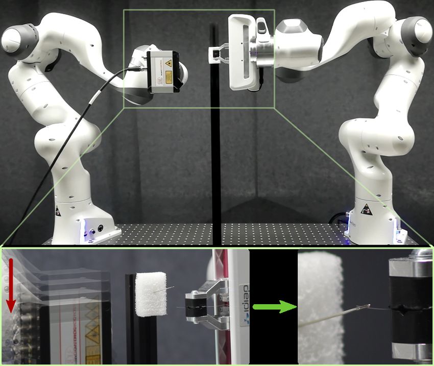
approach to modeling objects of various sizes, e.g. bridges
                                                                               [14] or daily-life objects [15]. We here study the applicability
                                                                               at much lower scales.
                                                                                  Finally, we highlight the high reproducibility of this work.
                                                                               By using popular collaborative robots, commercially avail-
                                                                               able sensors, benchmark tools [2] and common daily-life
Fig. 2: Difference between repeatability and accuracy as per ISO norm          objects (e.g. needles, threads), our results are easy to replicate
9283:1998 [8]. Each black point corresponds to an illustrative robot motion,   when compared to other works on the topic that require more
directed to the red ‘×’ in the middle. Modern collaborative robots tend
to belong to the third case (better repeatability than accuracy). Image        specialized robots, objects and setups, e.g. [5], [7], [12].
reproduced from [9].
                                                                                              III. PROPOSED APPROACH
      bility to implement rich sensing behaviors; and                          A. Overview
  4) leveraging pre-existing CAD models for sub-                                  The proposed approach revolves around the setup in Fig. 1.
      millimeter assembly tasks.                                               In that figure we see one robot holding a high-resolution laser
  To the best of our knowledge, no previous work has                           scanner and another holding a thread. Throughout the paper
addressed the issue of sub-millimeter manipulation with                        we will refer to the former as the sensing arm and the latter
collaborative robots using high-resolution laser sensing. The                  as the assembling arm. While in Fig. 1 the assembling arm
impact of our solution is not limited to the applications                      is holding a thread, generically this can be any object that
showcased in Sections IV–V, but has potential in any area                      needs to be inserted/fit into another object. We will assume
requiring small part manipulation, e.g. watch-making [1] and                   that the action that the assembling arm must perform comes
surgery [7] (we discuss possible limitations in Section VI).                   down to an insertion (threading, assembly or other).
                                                                                  Figure 3 gives an overview of our method. Both
                      II. RELATED WORK
                                                                               arms start    with the knowledge of the insertion pose,
                                                                                                    T
   Visual servoing [3] is a classical approach for handling

                                                                               pins = xT        T
                                                                                           ins qins   where xins ∈ R3 , qins ∈ S 3 . This pose
uncertain feedback signals, whether proprioceptive or from                     represents an initial guess about where the insertion will take
the environment. Therefore, it has been a popular choice                       place in the robot workspace and is used to bring the laser
in past works on small parts manipulation [7], [5], [10],                      scanner close enough that a point cloud of both the object to
[11], [12]. The answer to what type of visual servoing                         be inserted and its counterpart (where it will be inserted) can
should be used often boils down to the specificities of the                    be collected. Both pins and the initial poses of both arms
application such as the available hardware and the properties                  (see first two boxes in Fig. 3) can be collected beforehand,
of the scene and objects involved (e.g. lighting, textures).                   e.g. by kinesthetic teaching.
Recent work from Roveda et al. on 6D pose estimation                              Once the scanner is close enough to the insertion pose, a
[6] brings forward the insight that CAD-based methods are                      point cloud Pscan is collected. This point cloud can contain
well suited for dynamic scenarios, such as Industry-4.0-type                   sub-point-clouds that correspond to both the object to be
plants where appropriate lighting is often not guaranteed and                  inserted and the insertion target (e.g. a thread and a needle).
where objects often have little texture. Similarly to our work,                With Pscan , point cloud registration is performed (fourth box
[6] relies on point cloud registration to find object poses,                   in Fig. 3), against a reference point cloud Pref , from which
however at a much larger object scale. We follow their insight                 the poses of the object to be inserted pobj and the insertion
and rely on CAD models to obtain reference point clouds                        target p∗ins are extracted. With pobj and p∗ins , a trajectory
for registration. When not available, we use the sensing arm                   that brings the end-effector to the final insertion pose is
to model relevant objects. Interestingly, Tamadazte et al.                     computed and sent to the assembling arm to be tracked (last
[5] also proposed a CAD-model-based tracking method, but                       two boxes in Fig. 3). Since the resulting trajectory will have
applied to visual servoing (without point cloud registration).                 a very low amplitude, any modeling errors (e.g. kinematic
Their micro-assembly approach is, however, not trivial to                      uncertainty) that might exist are unlikely to accumulate
extend to dynamic environments like the ones we envision.                      enough to compromise the insertion.
   Our approach can be seen as a form of visual servoing                          The approach that we propose is both modular and generic
where the sensory feedback is not provided continuously                        by design. For instance, any box in Fig. 3 plays a distinct
but every time a new scan is performed. Due to the low                         role that depends only on the completion of the previous one
amplitude of the corrective trajectory that is computed, pro-                  in the chain. Additionally, we impose no constraint on how
prioception errors do not accumulate to a degree where the                     each module is implemented, e.g. the specific motion of the
task is compromised. Additionally, the fact that the computed                  sensing arm or the registration algorithm. Next, we describe
trajectory is relative, i.e., computed between two object poses                our proposed implementations and a few considerations.
represented in the same reference frame, alleviates the need
for very precise calibrations. The distinguishing feature of                   B. Scanning
our work on the sensing side is the very precise point clouds                     The sensing arm is responsible for obtaining a high-
that we operate on, which come from the use of a high-                         resolution point cloud Pscan of both the object to be inserted
resolution laser line scanner [13]. Depth sensing is a popular                 and the part where it will be inserted (both assumed rigid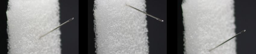
Algorithm 1: Pose estimation via point cloud regis-
                                                                       tration
                                                                         Input : Point clouds Pscan , Pref ; thresholds ρICP ,
                                                                                     ρrot ; initial estimate of object
                                                                                                                     orientation
                                                                                                                           T     q0
                                                                         Output: Pose of scanned object p̂ = x̂T q̂ T
                                                                      1 filter and downsample Pscan ;
                                                                                                                ∗
                                                                      2 initialize ICP best fitness score fICP = 1e6;
                                                                                   ∗
                                                                      3 while fICP > ρICP do
                                                                      4      p̂, P̂ ← RANSAC(Pscan , Pref );
                                                                      5      if dφ (q̂,q0 ) < ρrot then
                                                                      6           fICP , pICP ← ICP(Pscan , P̂);
                                                                                                  ∗
                                                                      7           if fICP < fICP        then
                                                                                         ∗
                                                                      8                fICP ← fICP ;
                                                                      9                p̂ ← pICP ;
                                                                     10           end
         Fig. 3: Diagram of the proposed dual-arm approach.          11      end
                                                                     12 end
enough not to deform significantly during insertion). Note
that there is the possibility to run multiple scans with
different poses if necessary (e.g. for improving Pscan ). An
important aspect to consider is the transformation between           of orientation mismatches. In order to quantify these, we
the sensor reference frame and the robot base. Here we used          compute an orientation error dφ (q̂, q0 ) [21] between the
the technical drawing from the sensor manual to manually             RANSAC-estimated orientation q̂ and q0 . We then evaluate
compute the pose of the scanner with respect to the robot            it against a threshold ρrot (set loosely enough to only reject
base. Calibration techniques like the one introduced by              unrealistic matches) to keep or reject the registration. Finally,
Lembono et al. [16] could be used either when an accurate            we define a threshold ρICP to stop the algorithm when
model is unavailable or to refine an initial estimate. It should     the distance between point clouds is small enough. Both
be noted, however, that the usual concerns with calibration          thresholds are chosen empirically. In Algorithm 1, f, P, p
precision are alleviated in our approach, since we rely on a         denote fitness scores, point clouds and poses, respectively.
relative trajectory, given the poses pobj , p∗ins (Section III-D).   Only the outputs of RANSAC() and ICP() that are relevant
                                                                     to the approach are indicated in rows 4 and 6.
C. Point cloud registration
                                                                     D. Trajectory planning and insertion
   From Pscan we estimate pobj and p∗ins . For this we rely
on point cloud registration. Note that, with a high-resolution          Using Algorithm 1 we obtain the poses p∗ins and pobj .
laser scanner such as the one we use, the point density will         After knowing these poses we use spline interpolation to
be very high. This is crucial for high-precision insertions.         compute a corrective Cartesian trajectory for the assem-
Similarly to [6] we pre-process Pscan , as a means to remove         bling arm {p1 , . . . , pT }, where T is the time horizon, that
noise and keep only the most important points. We also               compensates insertion pose errors. Since p∗ins and pobj are
need the original point clouds of the objects whose pose             represented in the same reference frame (the one of the
we intend to discover, which we refer to as Pref . One way           sensing arm), a trajectory that connects the two poses is
to obtain Pref is by scanning objects beforehand and storing         relative in nature, i.e. it can be applied as an offset so
their point clouds. However, as highlighted in [2], in many          that the robot moves incrementally from its current state.
automation processes the CAD models of the objects are               One positive side effect is that the need for a very precise
readily available. We propose to use them whenever possible          calibration of the sensor (as well as between the robot’s
to obtain Pref . A myriad of tools exist for converting CAD          bases, which here was manually estimated) is considerably
models to point clouds. Here we used Blender [17].                   alleviated. In this work we used spline interpolation to plan
   For pose estimation, we used Algorithm 1: a combination           relative trajectories but more elaborated planning can be
of RANSAC [18], for a coarse initial registration of Pscan           applied.
and Pref , and ICP [19], for refining the result. Particularly,
we relied on their implementations from the Point Cloud                   IV. EXPERIMENT I - NEEDLE THREADING
Library (PCL) [20]. From the end-effector pose, we compute             We applied the proposed approach to a needle threading
an initial guess of the manipulated object orientation q0 that       experiment, a scenario that demands high precision.
we use to filter out possible poor matches from RANSAC.
For objects that are not attached to the robot, other heuristics     A. Setup
can be used to compute q0 (e.g. a prior on pointing direction).        The experimental setup is shown in Fig. 1. The assembling
When poor registration from RANSAC occurs, which can                 arm holds a thread that is to be inserted in the needle
hinder ICP performance, it is most often a consequence               hole. Our evaluation considers three different aspects: initial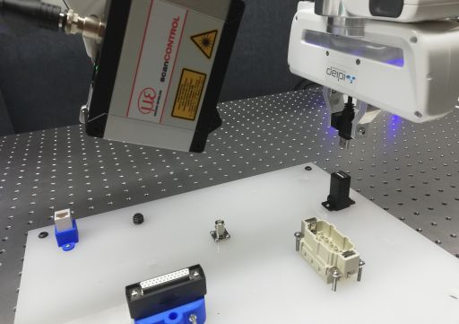
TABLE I: Success rates from needle threading experiment. Each number in
                                                                                 the columns ’Needle 1 ... 3’ corresponds to 10 insertion attempts.

                                                                                                                           Setting
                                                                                           Strategy                                                 Total
                                                                                                              Needle 1     Needle 2    Needle 3
Fig. 4: Three different needle poses used in the evaluation. We refer to each
                                                                                  Proprioception only +         50%          60%          70%       60%
of these settings as needle 1, needle 2 and needle 3, by the order they appear
                                                                                  IC1
in the figure.
                                                                                  Proprioception only +          0%          0%           0%         0%
                                                                                  IC2
                                                                                  With laser scanner            100%        100%†         90%       96.7%
                                                                                   †   Includes 2 failures that were successful upon re-scanning.

                                                                                 by taking IC1 and adding ∼ π/2 to the first joint (the rest
                                                                                 of the joints seen in Fig.5b adapt accordingly so that the
                                                                                 robot can accomplish the task). We hypothesize that IC1
                                                                                 will perform better than IC2 since it requires smaller joint
     (a) Insertion configuration            (b) Insertion configuration
                                                                                 displacements with respect to when pins was recorded. In
               1 (IC1).                              2 (IC2).                    other words, IC2 will result in higher pose errors (more failed
Fig. 5: Two different robot configurations used for threading. The effect
                                                                                 insertions). Specifically, the compared strategies were:
of changing the robot configuration on the insertion performance was                1) Proprioception only + IC1. The robot threads the
significant in the final results.                                                       needle using proprioception only and IC1 (Fig. 5a).
                                                                                    2) Proprioception only + IC2. The robot threads the
conditions, testing settings and threading strategies. Initial
                                                                                        needle relying on proprioception and IC2 (Fig. 5b).
conditions refer to the robot configuration before it starts
                                                                                    3) Insertion with sensory feedback (laser scanner). The
moving towards the needle. Testing settings correspond to
                                                                                        robot threads the needle using IC2 and compensates
different needle poses. Threading strategies pertain to the
                                                                                        for insertion pose errors using sensory feedback as per
robot configuration when inserting the thread and whether
                                                                                        Section III.
or not it uses sensory feedback. We now elaborate on these.
      a) Initial conditions: Every time the robot per-                           B. Hardware and control
forms an insertion, regardless of the threading strategy                            In our experiments (including Section V) we used a Micro-
and needle pose, it starts the motion at one of ten                              Epsilon LLT3000-25/BL laser scanner [13] attached to the
previously recorded joint configurations q (1) , . . . , q (10) .                left robot arm. We operated the scanner at its reference
These were recorded such that the position of the                                resolutions of 1.5µm (depth) and 12µm (x-axis, 2048
end-effector at each joint configuration q (i) is fur-                           points/profile). Moreover, for needle threading, we used a
ther away from the insertion pose than the previous,                             150µm-width thread and a needle with a hole width in the
i.e. kx(i) − xins k > kx(i−1) − xins k, i = 2, . . . , 10, where                 range 300 − 350µm along the smallest axis. Notice both the
x(i) = f (q (i) ) is the end-effector position and f (.) is the                  low scale and tolerance of this insertion task.
forward kinematics function.                                                        As robot platform, we used two 7-DoF Franka Emika
      b) Testing settings: We report results for three different                 Panda arms. The repeatability of the Panda arm, as reported
needle poses (Fig. 4). Testing the approach with different                       by the manufacturer, is 0.1mm. To the best of our knowledge
needle poses allows us to evaluate its robustness when task                      there is no official value for accuracy. In order to ensure the
conditions change. At the scale of this task, variations such as                 highest possible precision we used position control.
the ones in Fig. 5, which would normally seem negligible,
can cause a strong impact on performance and are worth                           C. Results
investigating. Prior to evaluations on any given needle pose,                       Here we describe the obtained results from each strategy.
we performed an insertion on that needle and stored the pose                     All the reported results (including those in Section V) can be
of the assembling arm end-effector pins . For each needle                        seen in the supplementary videos, also available at https:
pose we compared three different threading strategies.                           //sites.google.com/view/laser-cobots/.
      c) Threading strategies: We categorize threading strate-                         a) Insertion with proprioception only and IC1: Given
gies by whether the robot uses the laser scanner (insertion                      pins , the robot is commanded to reach that end-effector pose,
with sensory feedback) or not (proprioception only). In the                      starting from different poses in the workspace. Table I shows
latter case, we further break down the evaluation into which                     the obtained success rates for this strategy (first row). The
of two possible joint configurations IC1 and IC2 (Fig. 5)                        results show that, on average, the robot managed to thread
the robot uses during insertion. The null space of the task                      the needle 60% of the times. Figure 6 (second row) further
was used to bias the inverse kinematics (IK) solution to stay                    shows this. As the initial poses are farther and farther away
close to IC1 or IC2. The difference between IC1 and IC2 is                       from the insertion pose, the success rate decreases. This
that the former is the configuration of the robot during the                     can be due to a combination of the wider range of joint
recorded insertion and the latter is the configuration obtained                  motions required to reach the insertion pose, uncertainties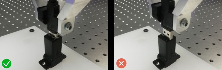
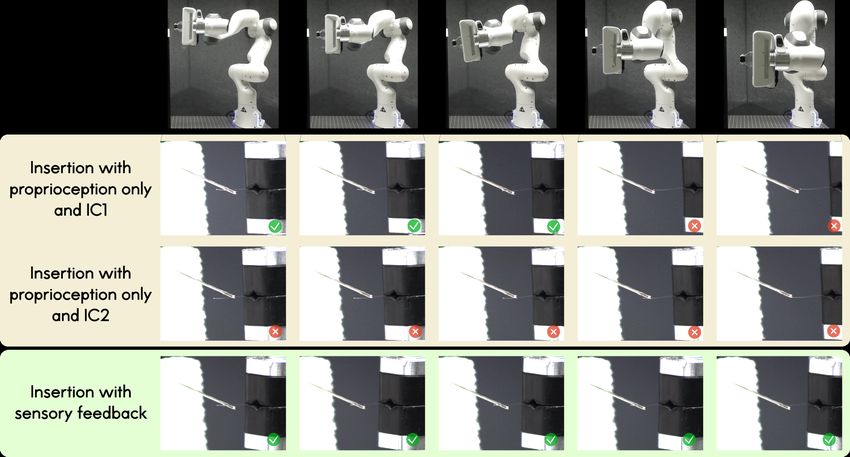
Fig. 6: Snapshots of the needle threading experiment, where we show 5 out of 10 results for the second needle pose in Fig. 4. The full results are
reported in Table I. Top row: Initial poses from which the robot performed the insertion. Second row: Insertion with proprioception only and IC1 as
robot configuration. Third row: Results for proprioception only and IC2. Bottom row: Insertion after correction from the laser scanner. Without sensory
feedback, the performance deteriorates both with the distance to the insertion pose and with the insertion configuration. A detailed visualization including
all cases is given in the supplementary videos.

in the planned insertion trajectories (which have a bigger
length as the robot starts farther away) and potentially the
accumulation of small deformations of the (non-rigid) thread
after several attempts. Nonetheless, owing to the 0.1mm
repeatability, a 60% success rate at this scale is noteworthy.
     b) Insertion with proprioception only and IC2: The
results showed that threading is never successful when the
                                                                                Fig. 7: Example of point cloud obtained after scanning the needle and the
insertion joint configuration differs from the original one by                  thread. The diagonal cluster of points is the needle point cloud Pscan . The
a non-negligible amount (see Table I, second row). The third                    registered model Pref (green) after Algorithm 1 is also shown. Note that
row in Fig. 6 is clear in this aspect, with the thread always                   in this experiment Pref was obtained by scanning the needle a priori. The
                                                                                small point cloud on the bottom-right corner is the thread tip.
ending up either below or before the needle. The arguments
given in the previous paragraph hold for this case as well.                     be automated, similarly to how the needle pose is found.
Here, since not only the starting poses, but also the insertion                 With the needle pose and the thread tip, the robot computes a
configuration differs by a significant amount, the previous                     low amplitude trajectory that compensates for the pose error,
observations are amplified.                                                     ensuring insertion. It is worth pointing out that the results in
     c) Insertion with laser scanner: Finally, using the pro-                   the third row of Table I include two attempts where the robot
posed approach with laser scanning, the previous results                        initially failed the insertion but, upon a re-scan, succeeded.
were considerably improved. As seen in Table I insertion                        Indeed, by bringing sensory feedback into the loop, one is
success rates reach values closer to 100%. In this scenario,                    able not only to detect errors but also to correct them. The
the robot was commanded to thread the needle, by first using                    bottom row of Fig. 6 shows 5 out of 10 successful insertions
its proprioception alone as in the previous cases. Once it                      for the needle 2 setting.
failed the insertion, the sensing arm performs a scan to obtain
a point cloud of the needle and the thread. Using this point                        V. EXPERIMENT II - USB CABLE INSERTION
cloud it runs Algorithm 1 to find the needle pose. Figure                          In a second experiment we used the NIST Task Board 1 [2]
7 shows an example of a scan. Notice the high density of                        to study the insertion of a USB plug (Fig. 8). This time we
the cloud, for such a small object. The device resolution                       obtained both socket and plug point clouds from their CAD
proves essential for this sort of tasks. In the bottom-right                    models, made available by NIST. Similarly to Section IV,
corner of the image we can see a small point cloud, which                       we computed success rates for 10 insertions, where the robot
corresponds to the thread tip. In our experiments we selected                   started at 10 different pre-recorded configurations. Note that
the tip manually on the GUI, but this step can alternatively                    success rates are one of the performance metrics proposed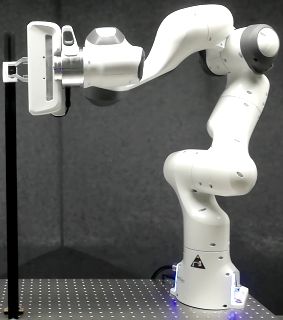
TABLE II: Success rates for 10 USB insertions.

                         Strategy             Total

                Proprioception only + IC1     90%
                Proprioception only + IC2     0%
                   With laser scanner        100%

                                                                   Fig. 9: Front and side view of the USB plug registration. White: Scanned
                                                                   point cloud Pscan . Green: Point cloud Pref , obtained from the CAD
                                                                   model (here aligned with Pscan after Algorithm 1). Since the plug was
                                                                   scanned from the front, we relied on a subpart of the whole CAD model.

                                                                   unsuccessful in the first attempt. A possible explanation is the
                                                                   presence of outliers in the point cloud, that affect registration.
                                                                   In our experience, rescanning and trying again (after the
                                                                   failure) can help. However, detecting failure might require
                                                                   a human operator to monitor the scene which may hinder
                                                                   the application in high-volume scenarios. Detecting failure
                                                                   and fully automating the solution was beyond the scope of
                                                                   this paper.
                                                                      In the experimental evaluations only position correction
                                                                   was required but some tasks may require orientation as well.
                                                                   Correcting for both position and orientation simultaneously
                                                                   can be difficult since orientation motions may require too
                                                                   large joint displacements, leading to significant (at this scale)
                                                                   pose errors. One possible way to use our approach in those
       Fig. 8: USB insertion setup with the NIST Task Board 1.     scenarios is to split the insertion into two phases, where the
                                                                   position and orientation errors are corrected sequentially.
in [2]. We considered two different robot configurations IC1          Finally, since the scanning arm is itself a collaborative
and IC2 following the same convention as in Section IV. In         robot, it is recommended to minimize the amplitude of joint
this case, we evaluated the approach for one single socket         motions during scans, so as to mitigate kinematic errors
pose. When inserting with sensory feedback, both socket and        as much as possible (which could lead to inaccurate point
USB plug are scanned and registered in order to compute            clouds). One might also be tempted to mount the sensor
pobj and p∗ins .                                                   on the assembling arm (to use just one robot) but since
   Table II shows the obtained success rates. As in the needle     the required motion between scan and insertion could be
scenario, all evaluations in the first two rows consisted of       large, there is a high chance that too much kinematic error
reaching a pre-recorded successful pose pins . Notice that, in     is accumulated and the task is compromised.
the first row, the success rate is higher than the one obtained
in the previous experiment. One possible explanation is that                            VII. CONCLUSIONS
the tolerance is slightly higher in this setup. Nevertheless, as      We proposed a solution that enables collaborative robots to
in the previous case, when changing the joint configuration to     perform high precision tasks. We have shown that, using our
IC2 the performance rapidly deteriorates (second row in Ta-        approach, a Panda robot could insert a 150µm thread into
ble II). In most practical applications, this effect will appear   a 300µm needle hole with a success rate close to 100%.
naturally since the robot needs to modify its configuration        The approach consists of a dual-arm system where one arm
when object poses change. Similarly to Section IV, sensory         controls the motion of a high-resolution laser scanner while
feedback strongly improved the performance (last row of            the other performs the insertion. It relies on the registration of
Table II). Figure 9 shows typical point clouds obtained for        scanned point clouds to find poses of objects of interest and
the USB plug. The high resolution once again stands out.           plan an insertion trajectory that corrects initially imprecise
The registration results were particularly robust, which is        ones. It is particularly well suited to low-volume, high-
well-attested by the 100% success rate.                            mixture manufacturing scenarios, where collaborative robots
                                                                   are meant to excel regardless of object size.
                      VI. DISCUSSION
                                                                      In future work we plan to extend the approach to consider
   The results in Sections IV and V show that the insertion        the end-effector and object orientations, and perform inser-
performance improves when feedback from the laser scanner          tions in optimal ways by relying on model predictive control
is considered by the assembling arm. This is especially            formulations on Riemannian manifolds [22]. The possibility
noticeable in the needle threading task where the tolerance is     to use other benchmarking protocols (e.g. [1]), additional
very low. Despite the positive results, some aspects deserve       metrics such as completion time [2] and to lower the total
attention. In Table I, three insertions with laser scanner were    cost of the solution will also be studied.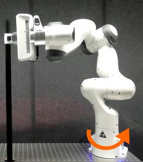
R EFERENCES                                        [21] M. J. A. Zeestraten, I. Havoutis, J. Silvério, S. Calinon, and D. G.
                                                                                     Caldwell, “An approach for imitation learning on Riemannian mani-
 [1] K. Chatzilygeroudis, B. Fichera, I. Lauzana, F. Bu, K. Yao, F. Khadi-           folds,” IEEE Robotics and Automation Letters (RA-L), vol. 2, no. 3,
     var, and A. Billard, “Benchmark for bimanual robotic manipulation               pp. 1240–1247, June 2017.
     of semi-deformable objects,” IEEE Robotics and Automation Letters,         [22] S. Calinon, “Gaussians on Riemannian manifolds: Applications for
     vol. 5, no. 2, pp. 2443–2450, 2020.                                             robot learning and adaptive control,” IEEE Robotics and Automation
 [2] K. Kimble, K. Van Wyk, J. Falco, E. Messina, Y. Sun, M. Shibata,                Magazine (RAM), vol. 27, no. 2, pp. 33–45, June 2020.
     W. Uemura, and Y. Yokokohji, “Benchmarking protocols for eval-
     uating small parts robotic assembly systems,” IEEE Robotics and
     Automation Letters, vol. 5, no. 2, pp. 883–889, 2020.
 [3] F. Chaumette and S. Hutchinson, “Visual Servo Control - Part I :
     Basic Approaches,” IEEE Robotics Automation Magazine, vol. 13, no.
     December, pp. 82–90, 2006.
 [4] P. Pastor, L. Righetti, M. Kalakrishnan, and S. Schaal, “Online
     movement adaptation based on previous sensor experiences,” in Proc.
     IEEE/RSJ Intl Conf. on Intelligent Robots and Systems (IROS), San
     Francisco, USA, September 2011, pp. 365–371.
 [5] B. Tamadazte, E. Marchand, S. Dembélé, and N. Le Fort-Piat, “CAD
     model-based tracking and 3D visual-based control for MEMS mi-
     croassembly,” The International Journal of Robotics Research (IJRR),
     vol. 29, no. 11, pp. 1416–1434, 2010.
 [6] L. Roveda, N. Castaman, P. Franceschi, S. Ghidoni, and N. Pedroc-
     chi, “A control framework definition to overcome position/interaction
     dynamics uncertainties in force-controlled tasks,” in Proc. IEEE Intl
     Conf. on Robotics and Automation (ICRA), Paris, France, 2020, pp.
     6819–6825.
 [7] C. Staub, A. Knoll, T. Osa, and R. Bauernschmitt, “Autonomous
     high precision positioning of surgical instruments in robot-assisted
     minimally invasive surgery under visual guidance,” in International
     Conference on Autonomic and Autonomous Systems (ICAS), Cancun,
     Mexico, 2010, pp. 64–69.
 [8] “Manipulating industrial robots – performance criteria and related
     test methods,” International Organization for Standardization (ISO),
     Geneva, Switzerland, Standard, 1998.
 [9] “What       are     accuracy     and      repeatability    in     indus-
     trial           robots?”            https://blog.robotiq.com/bid/72766/
     What-are-Accuracy-and-Repeatability-in-Industrial-Robots,
     Accessed: 2020/10/19.
[10] B. Tamadazte, G. Duceux, N. Le-Fort Piat, and E. Marchand, “Highly
     precise micropositioning task using a direct visual servoing scheme,”
     in Proc. IEEE Intl Conf. on Robotics and Automation (ICRA), Shang-
     hai, China, 2011, pp. 5689–5694.
[11] D. Xing, D. Xu, and H. Li, “A sequence of micro-assembly for
     irregular objects based on a multiple manipulator platform,” in Proc.
     IEEE/RSJ Intl Conf. on Intelligent Robots and Systems (IROS),
     Chicago, IL, USA, 2014, pp. 761–766.
[12] Y. Ma, K. Du, D. Zhou, J. Zhang, X. Liu, and D. Xu, “Automatic
     precision robot assembly system with microscopic vision and force
     sensor,” International Journal of Advanced Robotic Systems, vol. 16,
     no. 3, pp. 1–15, 2019.
[13] http://www.micro-epsilon.com/2D 3D/laser-scanner/
     scanCONTROL-3000/, Accessed: 2020/10/19.
[14] G. Paul, S. Webb, D. Liu, and G. Dissanayake, “Autonomous robot
     manipulator-based exploration and mapping system for bridge mainte-
     nance,” Robotics and Autonomous Systems, vol. 59, no. 7, pp. 543–554,
     2011.
[15] M. Krainin, P. Henry, X. Ren, and D. Fox, “Manipulator and object
     tracking for in-hand 3d object modeling,” The International Journal
     of Robotics Research, vol. 30, no. 11, pp. 1311–1327, 2011.
[16] T. S. Lembono, F. Suárez-Ruiz, and Q. Pham, “SCALAR - simulta-
     neous calibration of 2D laser and robot’s kinematic parameters using
     three planar constraints,” in Proc. IEEE/RSJ Intl Conf. on Intelligent
     Robots and Systems (IROS), Madrid, Spain, 2018, pp. 5570–5575.
[17] Blender Online Community, Blender - a 3D modelling and
     rendering package, Blender Foundation, Stichting Blender Foundation,
     Amsterdam, 2018. [Online]. Available: http://www.blender.org
[18] M. A. Fischler and R. C. Bolles, “Random sample consensus: A
     paradigm for model fitting with applications to image analysis and
     automated cartography,” Communications of the ACM, vol. 24, no. 6,
     pp. 381–395, 1981.
[19] P. J. Besl and N. D. McKay, “A method for registration of 3-D shapes,”
     IEEE Transactions on Pattern Analysis and Machine Intelligence,
     vol. 14, no. 2, pp. 239–256, 1992.
[20] R. B. Rusu and S. Cousins, “3D is here: Point Cloud Library (PCL),” in
     Proc. IEEE Intl Conf. on Robotics and Automation (ICRA), Shanghai,
     China, May 9–13 2011.
You can also read