Satellite data reception at Ny-Ålesund, Spitsbergen: From CHAMP to GRACE Follow-On
←
→
Page content transcription
If your browser does not render page correctly, please read the page content below
Falck et al., Satellite data reception at Ny-Ålesund, Spitsbergen … Fachbeitrag
Satellite data reception at Ny-Ålesund, Spitsbergen:
From CHAMP to GRACE Follow-On
Carsten Falck, Sven Reißland, Krzysztof Snopek and Franz-Heinrich Massmann
Summary den aktuell wichtigsten Einsatz als primäre Empfangsstation
The German Research Centre for Geosciences GFZ operates a der GRACE Follow-On Satellitenmission qualifiziert werden
satellite-receiving station at Ny-Ålesund, Spitsbergen, to re- konnte.
ceive data from scientific satellites in polar orbits. The station
has received data from the satellite CHAMP since 2001, but Keywords: NYA ground station, GRACE-FO primary downlink
soon also from other satellites like those of the GRACE-mis- station, S-band, GNSS radio occultation, Svalbard
sion. Notable is the continuous provision of received data
through this station at low latencies and operation costs,
which helped, e. g., to establish GNSS radio occultation
measurements on satellites as a novel observation type for 1 Introduction
weather forecasts. The station efficiency has been improved
constantly with technical and operational amendments over Most scientific satellites produce huge amounts of obser-
the years, so that it could even be qualified to serve for the vation data which must be sent to ground to be processed
actually most important task as the primary downlink station and evaluated. The minimum required frequency and the
of the GRACE Follow-On satellite mission. distribution over time of contacts for data downloads
between a specific satellite and ground stations depend
Zusammenfassung on the rate of on-board data generation, the on-board
Das Deutsche GeoForschungsZentrum GFZ betreibt eine Sa- data storage capacity and the downlink data rate (trans-
telliten-Empfangsstation in Ny-Ålesund auf Spitzbergen, um mission path to ground). Even more frequent contacts
Daten von wissenschaftlichen Satelliten in polaren Umlauf- might be needed to reduce data availability latencies for
bahnen zu empfangen. Die Station empfing ab 2001 die Daten time-critical applications, such as weather forecasts. This
des Satelliten CHAMP, bald darauf aber auch von anderen was the case for the satellite mission CHAMP (Reigber
Satelliten wie z. B. denen der GRACE-Mission. Bemerkens- et al. 2006), where all on-board data was received by
wert ist die kontinuierliche Bereitstellung der empfangenen ground stations in Germany, but most of it with too high
Daten durch diese Station mit kurzen Wartezeiten und nied- latencies to be useable for operational processing chains
rigen Betriebskosten, was z. B. dabei half, GNSS-Radiookkul- of weather forecast centres. A solution for this issue was
tationsmessungen auf Satelliten als neuen Beobachtungstyp found in the operation of an additional receiving anten-
für Wettervorhersagen zu etablieren. Die Leistungsfähigkeit na at Ny-Ålesund, Spitsbergen, which provided suffi-
der Station wurde über die Jahre durch technische und ope- ciently frequent contacts with CHAMP and later to other
rationelle Updates ständig verbessert, sodass sie sogar für satellites as well.
Fig. 1: Satellite receiving station NYA at Ny-Ålesund
DOI 10.12902/zfv-0290-2020 © Wißner-Verlag 145. Jg. 2/2020 zfv 111
Fachbeitrag                                      Falck et al., Satellite data reception at Ny-Ålesund, Spitsbergen …

2 Determining characteristics of the location

The most important feature of the satellite receiving
station at Ny-Ålesund (short name NYA, Fig. 1) is the
high number of daily possible contacts to polar orbit-
ing satellites, which follows from the high latitude lo-
cation (78° 55′ N, 11° 56′ E). Fig. 2 shows the areas of
visibility for receiving antenna elevations of 5° and
above (typical for satellite tracking) at the ground sta-
tion NYA (green circle) and at Potsdam, Germany, as a
lower latitude reference (red circle, 52° 23′ N, 13° 04′ E).
                                                                 Fig. 3: RF-power scan of environment at 2.25 GHz

                                                                 received radio power as it was detected at a telemetry
                                                                 receiver input port at a typical S‑band satellite down-
                                                                 link frequency (2.25 GHz) when one of the NYA-anten-
                                                                 nas scanned the local horizon up to an elevation of 15°.
                                                                 The orange colours correspond to the detected natural
                                                                 (thermal) radio emission of the environment (local hori-
                                                                 zon with mountains) in contrast to the colder sky behind
                                                                 it. Only one manmade radio source on ground, actually
                                                                 spurious emissions of a local instrument (DORIS2 beacon)
                                                                 in 120° azimuth direction, and one in the sky, probably
                                                                 from a passing satellite (not seen there on other scans),
                                                                 were found with low signal levels in the experiment
                                                                 (about 8 dB over coldest background directions).
                                                                     In spite of being located close to the North Pole (dis-
                                                                 tance about 1230 km), Ny-Ålesund is reachable through
                                                                 regular travel connections (small aircrafts and ships) and
                                                                 has a moderate climate. Practically all kind of local in-
                                                                 frastructure and services (airport, harbour, road system,
Fig. 2: Areas of visibility for NYA and Potsdam                  energy, board and lodging etc.) is provided by the Nor-
                                                                 wegian Kings Bay Company. Glass fibre cables from Ny-
Typical polar Low-Earth Orbit (LEO) satellite ground             Ålesund to the European mainland guarantee excellent
tracks (satellite altitude 500 km, orbit inclination 89°) for    data transfer connectivity (since 2015). Occasional need-
a period of 24 hours are displayed as blue lines. The parts      ed hands-on support for the NYA station is granted by
of the tracks which are inside an area of visibility can         the local German-French AWIPEV3 research station.
be used for telemetry contacts. It is evident that only 4
or 5 of the daily orbits (15 to 16) could be accessed from
Potsdam, but all of them by NYA. Such frequent con-
tacts, respectively the shorter periods without contacts,        3 Station history
are in practice indispensable for a low latency provision
of satellite data and frequent satellite status monitoring.      The first satellite telemetry receiving antenna at the sta-
More contacts result also in a higher total contact time         tion was purchased in 1996 as part of a so called mobile
and thus effectively in a higher data reception capacity.        ground station, which was initially funded and operated
   Ny-Ålesund is declared as a radio quiet area (20 km           jointly by GFZ and DLR for campaigns in other areas of
radius). The regulation is particularly strict for signals       the world (Roessner et al. 2001, Xia 2002). GFZ want-
between 2 to 32 GHz, as that frequency range is used by          ed to stimulate the operational assimilation of GNSS
local VLBI1 radio astronomy facilities (a VLBI antenna           radio occultation data (GNSS‑RO) by weather forecast
is visible on the left in Fig. 4). It prevents NYA from          centres with frequent downlinks from CHAMP, which
transmitting to satellites, which is why it is only a re-        was launched in 2000 and the first satellite that could
ceiving station (no uplink). The local radio ban includes
even WIFI and Bluetooth, which must be switched off
                                                                 1 Very Long Baseline Interferometry
by visitors before arriving at Ny-Ålesund. However, NYA          2 Doppler Orbitography and Radiopositioning Integrated by
also benefits from that situation, as it reduces the prob-       Satellite
ability of radio interference from local sources and thus        3 Alfred-Wegener-Institute and Institut polaire français Paul-
the effort to handle them. Fig. 3 shows exemplary the            Emile Victor

   112    zfv   2/2020 145. Jg.                © Wißner-Verlag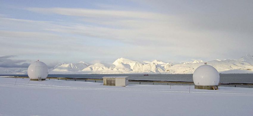
Falck et al., Satellite data reception at Ny-Ålesund, Spitsbergen … Fachbeitrag
rovide such data regularly (Wickert et al. 2001). DLR
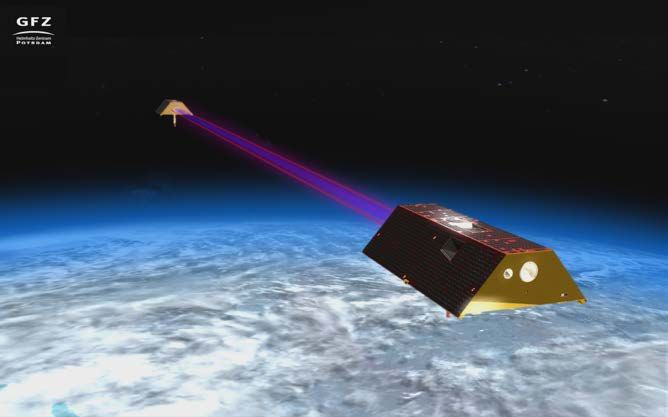
p 4 Qualification for GRACE-FO mission
had an interest in frequent contacts with their satellite
BIRD (launched 2001). Both satellites were in polar orbits The US-German GRACE-Follow-On mission (short
and Ny-Ålesund was identified as an excellent location GRACE-FO), with measurements for the determina-
to install an antenna for the desired additional downlink tion of the Earth’s gravity field (Flechtner et al. 2016)
contacts. GFZ already had good relations to some insti- and GNSS‑RO based atmospheric sounding on two sat-
tutions onsite for many years, e. g. with the Norwegian ellites (Fig. 5), is jointly managed by NASA and GFZ.
Mapping authority (Statens Kartverk), for the operation
of GPS- and PRARE4-stations (Falck et al. 2013). As a
consequence the antenna was supplemented with a basic
S‑band receiver system in 2000 (executed by DLR) and
installed at Ny-Ålesund in spring 2001 (managed and fi-
nanced by GFZ).
From the beginning there have been more contacts
per day at Ny-Ålesund with CHAMP than with BIRD.
© Filmhaus Berlin/GFZ
Fig. 5: GRACE-FO satellites
In the planning phase of the project (phase A) it became
clear, that the satellites had an at least three times high-
er on-board data generation rate, compared with the
preceding GRACE mission, which required increased data
downlink capacities. The original concept with an ac-
cordingly three times higher downlink data rate and a
Fig. 4: Installation of the second antenna (NYA-2) in 2005 limited number of daily contacts with ground stations in
Germany was not sufficient to receive all of the satellite
BIRD suffered from technical problems on-board which data. One possible solution was to change the layout of
affected the satellite operation (Attitude and Control GRACE‑FO’s telemetry system from S‑band to X‑band,
Subsystem, breakdown in 2004). The practical coopera- which could provide higher bandwidth, but at higher
tion between GFZ and DLR for the antenna (later named costs. The other option was to plan for more daily down-
NYA‑1) phased out slowly (last DLR maintenance visit link contacts to ground stations, which was even more
at Ny-Ålesund in spring 2002), but GFZ wanted to con- costly, at least if the additional contacts had to be ac-
tinue the data reception from CHAMP and even to ex- quired from well-established stations as operated, e. g.,
tend activities, e. g., with the reception of data from both by DLR, ESA or NASA. More daily contacts were strongly
GRACE satellites (launched 2002). Thus GFZ invested in preferred anyway, as they promised additional benefits,
the replacement of already aged components, new ver- e. g., a proper support of the well-proven GNSS‑RO pro-
satile and redundant receiving systems, an extension of cessing chains and the possibility for a closer monitoring
the operation cabin and an additional, second antenna of GRACE‑FO’s on-board systems. Taking into account
(Fig. 4), and built up in-house competence to operate the the reliable operation of NYA for CHAMP, GRACE and
station independently from other parties. other satellites over more than a decade and the com
The single antenna site at Ny-Ålesund grew to a small parable low operation costs, it was decided to qualify and
ground station with significantly increased capacity and set in NYA, if possible, as the primary downlink station
exclusive control by GFZ and supported more satellite for GRACE‑FO.
missions (GRACE, SAC‑C, TerraSAR‑X, TanDEM‑X, Fly- The qualification of NYA actually meant to achieve,
ing Laptop, GRACE Follow-On). However, all receiving prove and document compatibility to the mission’s re-
activities except for GRACE-Follow-On were and are ex- quirements and to react on concerns of a critical review
ecuted on a best effort basis, meaning without stringent board which engaged external and NASA experts. These
commitments for GFZ. addressed of course all relevant technical details, but
also questions about redundancies and the perspective of
sustainability. As a consequence, GFZ invested, e. g., in
another two new telemetry receivers and a local stock of
4 Precise Range And Range-Rate Equipment essential spare parts.
© Wißner-Verlag 145. Jg. 2/2020 zfv 113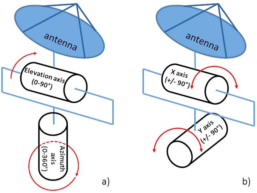
Fachbeitrag Falck et al., Satellite data reception at Ny-Ålesund, Spitsbergen …
New software for the operation and complementary All qualification tasks were concluded successfully
supervision of both antennas was developed by GFZ as and the compatibility of NYA for GRACE‑FO was con-
well as new software for the precise control of local sys- firmed. NYA was selected by the GRACE‑FO project as
tem clocks with GPS, which improved the performance, the primary (main) downlink station and received first
reliability and perspective of sustainability of the sta- signals from a GRACE‑FO satellite already in its first
tion (Falck 2018). The software includes special features orbit, 80 minutes after launch (May 22, 2018). It now
that support the determination of the antenna radia- routinely receives all data from both GRACE‑FO satel-
tion pattern and the ratio of the antenna gain to system lites with an excellent performance and reliability, which
noise (G/T), which had to be known for the link budget enables the desired constantly frequent low latency data
calculation of contacts with the GRACE‑FO satellites distribution to all project partners.
(Falck 2015). The GFZ-made operation monitoring and
data processing software system at Potsdam was mod-
ernized and backed up with a second installation at the
GFZ subsidiary at Oberpfaffenhofen. 5 Actual station design
NYA employs two S‑band (2.2–2.4 GHz) antenna systems
with parabolic reflectors (diameter 4 m), which are shel-
tered against the rough climate conditions on Spitsber-
gen by heatable radomes. The antenna positioning sys-
tems have a different layout of their axes orientations.
NYA‑1 uses an “elevation over azimuth” system (Fig. 8a)
and NYA‑2 a “X over Y” system (Fig. 8b), which has a
better performance for contacts with satellites passing
close to zenith.
Fig. 6: NYA receiver at Airbus-DS facilities for RF-compa
tibility tests with GRACE-FO telemetry downlink system
Fig. 8: Layout of NYA antenna positioning systems
The antenna feed of NYA‑1 is currently capable to re-
ceive right hand circular polarisated (RHCP) signals only.
Fig. 7: Example of BER-test result The antenna feed of NYA‑2 allows the simultaneous re-
ception of RHCP and LHCP (left hand circular polarised)
Another example for the qualification activities are the signals, in principle also in the X‑band, but this feature
RF (radio frequency) compatibility tests with one of the is not fully implemented yet. Both antennas are directed
NYA telemetry receivers (“blue box” on table in Fig. 6) to the passing satellites on the basis of actual, respective-
in a direct connection to the satellite telemetry systems ly predicted satellite orbit information. This information
(flight models) at the satellite manufacturer’s facilities must be as precise as possible as there are no provisions
(Airbus Defence and Space, Friedrichshafen, Germany). to detect (and compensate) actual antenna pointing er-
It had to be shown, among other things, that the bit error rors during satellite contact times (no auto-tracking).
rate of the telemetry downlink path (BER, red graph in All receivers and devices for antenna operation are
Fig. 7) was below a certain limit (blue graph) over a range placed in a small operation cabin between the radomes
of defined signal to noise ratios (green graph corresponds (Fig. 1). At least single redundancy is installed for almost
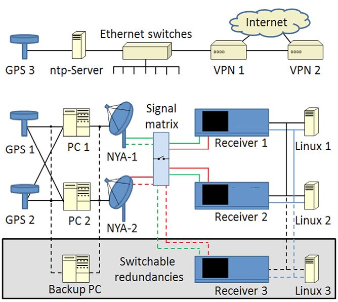
to theoretical optimum). all devices and functions (Fig. 9). Each of the three dual
channel telemetry receivers can receive signals from both
114 zfv 2/2020 145. Jg. © Wißner-Verlag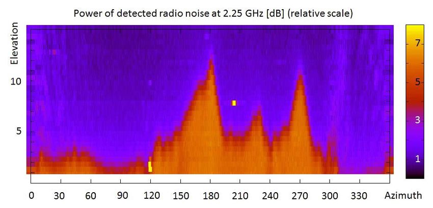
Falck et al., Satellite data reception at Ny-Ålesund, Spitsbergen … Fachbeitrag
Fig. 10 visualizes an exemplary scheduling for both
antennas over one day and the tracking times of five
satellites, symbolized by small coloured bars. Each of the
16 rows in the graph represents 90 minutes of the day
(starting with hours on left scale), the upper part of each
row is the scheduled activity of NYA‑1 and the lower
part is the scheduled activity of NYA‑2. The scheduling
is done automatically and usually there is no need for
manual corrections. These are required only occasionally,
e. g., due to special requests for not tracking at certain
times. In the example (Fig. 10) the times of satellite vis-
ibility were partly overlapping in the morning time. In
such a case GRACE‑FO contacts are scheduled with the
highest priority (green, orange) while some of the other
contacts with TerraSAR‑X, Tandem‑X and Flying Laptop
(TSX, TDX and FLT) were shortened or skipped.
The illustration shows also a measure to prevent
Fig. 9: NYA system design possible data gaps due to eventual technical prob-
lems with one of the antennas, which is regularly ap-
antennas simultaneously (IN-SNEC 2006). Anyway, two plied for GRACE‑FO reception. The GRACE‑FO satellites
receivers are always operated in parallel and provide hot fly in a twin-constellation with a nominal distance of
redundancy. The third receiver is on standby (cold re- 220 km. They thus appear at the station very close in
dundancy). Also the antenna operation computers with time and could be tracked simultaneously in principle,
their GPS-based timing systems have a redundant layout each with one of the two antennas. However, only one
and remotely switchable local spares. The clocks of de- of the GRACE‑FO satellites is tracked at a time, but with
vices with lower timing requirements, such as monitoring both antennas in parallel as displayed by the green and
cameras or remote control systems, are synchronised to a orange double bars in Fig. 10. In the next orbit the other
local ntp-server (network time protocol), which can also GRACE‑FO satellite is tracked, again with both antennas.
serve as a provisional backup for the antenna operation. This approach results in a higher data delivery latency
An independent and isolated backup communication of up to two orbital periods, but improves the reliability
network (ethernet) is in place for the essential receiver of the downlink process. Other satellites than GRACE‑FO
operation, in case of problems with the prime network, are usually tracked with one antenna only.
which is connected to the Internet (like the other devices)
via VPN (Virtual Private Network encryption).
6 Regular station operation
NYA has been operated unmanned all year round since
2001. This kind of operation requires extra equipment
for remote control and monitoring and a high level of
automation. Even the contact scheduling process is high-
ly automated, but not fully automatic, as the receiving
activities must be correlated with changing satellite op-
eration plans and fluctuating orbits. Accordingly, GFZ
prepares NYA operation schedules once per week or at Fig. 10: Example of NYA schedule for 1 day and 5 satellites
any time when there is a need for short-term changes,
and sends them to NYA as so called jobfiles (Falck et al. The antenna tracking and satellite data reception itself
2017). The jobfile structure is rather simple but contains are fully automatic and usually do not need any local or
sufficient information for an automatic system config- remote attendance at any time, but are monitored from
uration and satellite tracking at the station. A precise remote, at least occasionally, during regular office hours.
antenna pointing in spite of fluctuating satellite orbits Tailored monitoring tools allow a prompt control of the
is addressed by frequent updates of orbit information. downlink success. They visualize received versus trans-
These are based especially on the latest data from the mitted (scheduled) satellite data and the status (colour
satellite on-board GNSS measurements and sent to the coded) of on-board instruments and also the antenna and
station up to five times per day. receiver operation records, such as antenna directions,
© Wißner-Verlag 145. Jg. 2/2020 zfv 115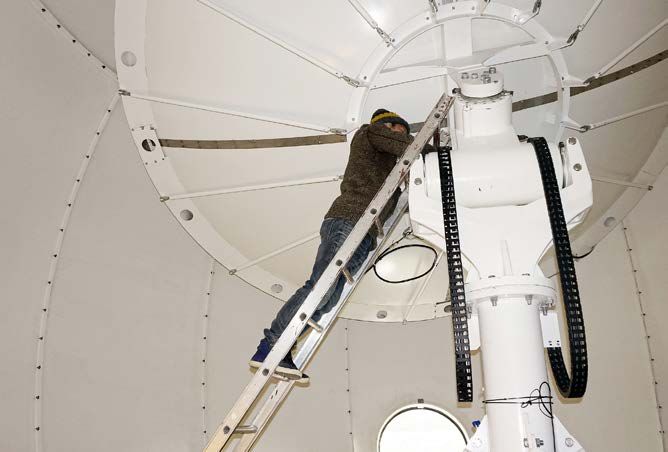
Fachbeitrag                                      Falck et al., Satellite data reception at Ny-Ålesund, Spitsbergen …

                                                                broadband radio frequency signal source for tests with
                                                                the antenna systems, which avoids conflicts with the lo-
                                                                cal radio emission restrictions. The direction to the sun is
                                                                constantly changing of course, but precisely computable
                                                                for any actual time of measurements. The signal strength
                                                                (activity) of the sun is also known with sufficient certain-
                                                                ty, as the solar flux is monitored by related observatories.
                                                                The antenna pointing accuracy and the system’s gain to
Fig. 11: “GFZ dump-browser” tool providing a quick view         noise ratios are checked regularly with this approach.
on received satellite data                                          Other important maintenance tasks are the lubrication
                                                                of the antenna turntable systems (Fig. 12), the control
signal strengths and Doppler offsets. In the example of         and cleaning of fans and air filters, software updates, and
Fig. 11 (cut-out from “GFZ dump-browser” screenshot)            the replacement of faulty or aged components, such as
there was an outage (traces lose nominal blue colour)           hard disks and computers. Major software modifications,
of the both inter-satellite ranging instruments (K‑band         e. g., w. r. t. antenna operations or internet connectivity,
microwave and laser) on GRACE‑FO‑2, which caused sig-           are tested and implemented only onsite, to prevent dam-
natures on the corresponding traces for GRACE‑FO‑1 as           ages or problems in case of eventually required system
well (opposite side of inter-satellite tracking).               recoveries.
    There are also functions for automatic failure detec-
tion at the station and at GFZ. These detect data gaps
or problems as discussed above or somehow smaller
problems, e. g., too high deviations between commanded
and reported antenna directions, and send correspond-
ing alert emails and SMS messages to related staff at
GFZ. The station’s activity is logged in great detail in
principle (e. g., antenna movements and receiver settings)
necessary also to fulfil one of the requirements of the
Norwegian authorities, which enforce the regulations of
the Svalbard Treaty (international Spitsbergen contract).
A Norwegian control commission visits NYA twice per
year to check the station’s compliancy with the contract
(e. g., non-military usage) and other related laws and reg-
ulations (Norwegian and local).                                 Fig. 12: Maintenance work at NYA-2 antenna
    All satellite data from NYA is automatically trans-
ferred to GFZ immediately after reception. At GFZ it is            Examples for enhancement works in the last years are
forwarded to project partners and pre-processed, where          the installation of additional UPS (uninterruptible power
applicable, which includes further decoding and sorting         supply) capacities, redundant signal and power cables in
to the different data sources (instruments, house-keep-         extra trenches to both antennas and advanced automatic
ings). Pre-processed data is provided to several process-       reporting functions. Many of these upgrades were trig-
ing chains, e. g., for satellite orbit determination, at-       gered by the GRACE‑FO mission. In 2020 it is planned
mospheric sounding (for weather forecasts) and gravity          to continue tests that have already started for a possible
determination and also to operation monitoring tools            future reception of X‑band signals at NYA. X‑band sys-
such as shown in Fig. 11.                                       tems are more complex than S‑band systems, but used by
                                                                several satellite missions, as they allow higher data-link
                                                                bandwidths (compared to S‑band).

7 System maintenance and enhancement

Regular maintenance is required to preserve the reliable        8 Outlook
function of the NYA station. All systems are monitored
permanently and some maintenance (e. g., small software         The NYA satellite receiving station will continue to serve
patches) can be done from remote at any time, but real          as the primary downlink station for the GRACE‑FO mis-
hands-on maintenance on-site is only once per year.             sion and to receive data from the other currently sup-
   Usually GFZ staff visits the station in the summer sea-      ported satellite missions. More satellite missions may be
son. An obvious reason for that time is the more friendly       supported in the future, possibly even with additional
weather conditions, another is the continuous visibili-         downlink capacities in the X‑band, which are planned to
ty of the sun (polar day). The sun is used as a natural         be developed in the near future.

   116   zfv   2/2020 145. Jg.                © Wißner-Verlag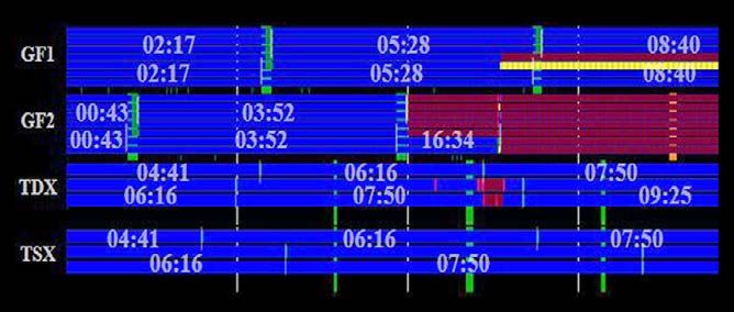
Falck et al., Satellite data reception at Ny-Ålesund, Spitsbergen …                                            Fachbeitrag

References                                                              Wickert, J., Reigber, C., Beyerle, G., König, R., Schmidt, T., Grun-
Falck, C. (2015): NYA antennas G over T measurements. Technical            waldt, L., Galas, R., Meehan, T., Melbourne, W. G., Hocke, K.
   Report GFO-GFZ-TR-1002, Issue 1.0. Potsdam.                             (2001): Atmosphere sounding by GPS radio occultation: First
Falck, C. (2018): Preparation of the satellite receiving station at        Results from CHAMP. Geophysical Research Letters, 28, 17,
   Ny-Ålesund for upcoming satellite missions by means of new              pp. 3263–3266.
   made-to-measure antenna operation software. GFZ (Ed.): Sci-          Xia, Y. (2002): INSAR activities in Central Asia using a mobile SAR
   entific Technical Report, 17/11. DOI: 10.2312/GFZ.b103-17113.           receiving station. IGARSS 2001, Sydney, vol. 1, pp. 407–409.
Falck, C., Flechtner, F., Massmann, F.-H., Raimondo, J.-C., Reig-          DOI: 10.1109/IGARSS.2001.976173.
   ber, C., Scherbatschenko, A. (2013 online): Betrieb des PRA-
   RE-Bodensegments für ERS-2: Abschlussbericht 2003. Scientif-
   ic Technical Report; 04/20, Deutsches GeoForschungsZentrum
   GFZ, Potsdam, pp. 74. DOI: 10.2312/GFZ.b103-04202.                   Contact
Falck, C., Reißland, S., Snopek, K., & Massmann, F. H. (2017): NYA      Dr. Carsten Falck | Sven Reißland
   Jobfile Description. Technical Report NYA-GFZ-SP-1001, Issue         Helmholtz Centre Potsdam
   1.0.                                                                 GFZ German Research Centre for Geosciences
Flechtner, F., Neumayer, K., Dahle, C., Dobslaw, H., Fagiolini, E.,     Telegrafenberg, 14473 Potsdam
   Raimondo, J., Güntner, A. (2016): What Can be Expected from          falck@gfz-potsdam.de | svenr@gfz-potsdam.de
   the GRACE-FO Laser Ranging Interferometer for Earth Science
   Applications? Surveys in Geophysics, 37, 2, pp. 453–470. DOI:
   10.1007/s10712-015-9338-y.                                           Dr. Krzysztof Snopek | Franz-Heinrich Massmann
IN-SNEC (2006): CORTEX-XL Series-RTR USER’S MANUAL. DTU                 Helmholtz Centre Potsdam
   000499 Ver.2 – Rev. 0.                                               GFZ German Research Centre for Geosciences
Reigber, C., Lühr, H., Grunwaldt, L., Förste, C., König, R.; Mass-      c/o Edmo – Sonderflughafen Oberpfaffenhofen
   mann, F.-H., Falck, C. (2006): CHAMP Mission 5 Years in Orbit.       Claude-Dornier-Straße 1, 82230 Weßling
   In: Flury, J., Rummel, R., Reigber, C., Rothacher, M., Boedecker,    snopek@gfz-potsdam.de | fhm@gfz-potsdam.de
   G., Schreiber, U.: Observation of the Earth System from Space,
   pp. 3–16, Springer.
Roessner, S., Wetzel, H., Kaufmann, H., Samagoev, A. (2001): Sat-
   ellite remote sensing for regional assessment of landslide haz-
   ard in Kyrgyzstan (Central Asia). In: Tetzlaff, G., Trautmann, T.,
   Radtke, K. S. (Eds.). Bonn and Leipzig.

                                                                        This article also is digitally available under www.geodaesie.info.

                                                                               zfv-Fachbeiträge
                                                                          Alle Fachbeiträge der zfv stehen etwa drei bis vier
                                                                          Wochen nach Erscheinen der zfv als kostenloser PDF-
                                                                          Download unter www.geodaesie.info zur Verfügung.

                                                                        © Wißner-Verlag                      145. Jg. 2/2020   zfv   117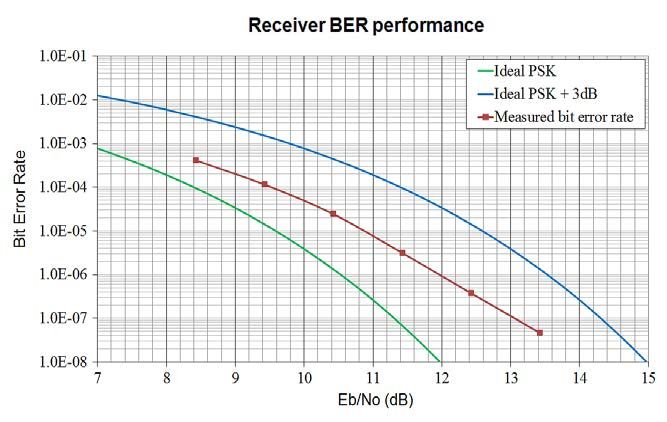
You can also read