Co introduction of precipitate hardening and TRIP in a TWIP high entropy alloy using friction stir alloying - Nature
←
→
Page content transcription
If your browser does not render page correctly, please read the page content below
www.nature.com/scientificreports
OPEN Co‑introduction of precipitate
hardening and TRIP in a TWIP
high‑entropy alloy using friction
stir alloying
Tianhao Wang1,2,5, Shivakant Shukla1,3,5, Bharat Gwalani1,2, Subhasis Sinha1,4,
Saket Thapliyal1, Michael Frank1 & Rajiv S. Mishra1*
Tuning deformation mechanisms is imperative to overcome the well-known strength-ductility
paradigm. Twinning-induced plasticity (TWIP), transformation-induced plasticity (TRIP) and
precipitate hardening have been investigated separately and have been altered to achieve exceptional
strength or ductility in several alloy systems. In this study, we use a novel solid-state alloying
method—friction stir alloying (FSA)—to tune the microstructure, and a composition of a TWIP high-
entropy alloy by adding Ti, and thus activating site-specific deformation mechanisms that occur
concomitantly in a single alloy. During the FSA process, grains of the as-cast face-centered cubic
matrix were refined by high-temperature severe plastic deformation and, subsequently, a new
alloy composition was obtained by dissolving Ti into the matrix. After annealing the FSA specimen
at 900 °C, hard Ni–Ti rich precipitates formed to strengthen the alloy. An additional result was a
Ni-depleted region in the vicinity of newly-formed precipitates. The reduction in Ni locally reduced
the stacking fault energy, thus inducing TRIP-based deformation while the remaining matrix still
deformed as a result of TWIP. Our current approach presents a novel microstructural architecture
to design alloys, an approach that combines and optimizes local compositions such that multiple
deformation mechanisms can be activated to enhance engineering properties.
High-entropy alloys (HEAs) have attracted considerable interest since they were first conceptualized and synthe-
sized by Yeh1. This ongoing interest is due mainly to HEAs maintaining excessive entropy-driven phase stability
and unique mechanical properties that include high strength at both room temperature and high temperature,
good wear resistance, corrosion resistance and fatigue properties2,3. HEAs also provide a completely new com-
positional space for designing novel materials with exceptional properties. Recent developments in the field of
non-equiatomic HEAs have focused on introducing TRIP (transformation-induced plasticity)4, TWIP (twin-
ning-induced plasticity)5, and joint activation of TWIP and TRIP6,7 by designing metastable alloys. Moreover,
researchers have also incorporated precipitation hardening (PH)8 and interstitial solid s olution7 in the HEAs as
additional strengthening mechanisms. The preliminary study on TRIP-DP (dual phase)-HEA ( Fe50Mn30Co10Cr10
at.%, γ (FCC) and ε (HCP) phases) by Li et al.4 demonstrated that both strength and ductility can be improved
by a strain-induced γ to ε transformation. Inspired by this finding, Nene et al.9 modified the alloy composition
by adding Si and increasing Cr (Fe42Mn28Co10Cr15Si5 at.%) and thus, increasing metastability of the γ phase to
capitalize on the TRIP effect. Meanwhile, Sinha et al.5 exchanged Co for Ni ( Fe42.8Mn28.3Cr14.8Ni9.6Si4.5 at.%) to
increase the stacking fault energy to favor TWIP during plastic deformation10–12. Hence, the previous work
demonstrated the possibility of both TWIP and TRIP in this alloy system through compositional tuning.
Furthermore, a combined body of l iterature5–9 suggests that even minor alloying addition can greatly impact
HEA strengthening mechanisms such as TRIP, TWIP and PH. Yet, the limited development of alloys can be
attributed to conventional development methods that include casting, thermomechanical processing, and anneal-
ing process. In this study, friction stir alloying (FSA), a novel solid-state alloying method derived from friction
stir processing (FSP)13, was applied for simultaneous grain refinement and alloying process. A similar approach
1
Department of Materials Science and Engineering, University of North Texas, Denton, TX 76207, USA. 2Present
address: Pacific Northwest National Laboratory, Richland, WA 99352, USA. 3Present address: Oak Ridge National
Laboratory, Oak Ridge, TN 37831, USA. 4Present address: Department of Metallurgical Engineering, IIT(BHU),
Varanasi, India. 5These authors contributed equally: Tianhao Wang and Shivakant Shukla. *email: Rajiv.Mishra@
unt.edu
Scientific Reports | (2021) 11:1579 | https://doi.org/10.1038/s41598-021-81350-0 1
Vol.:(0123456789)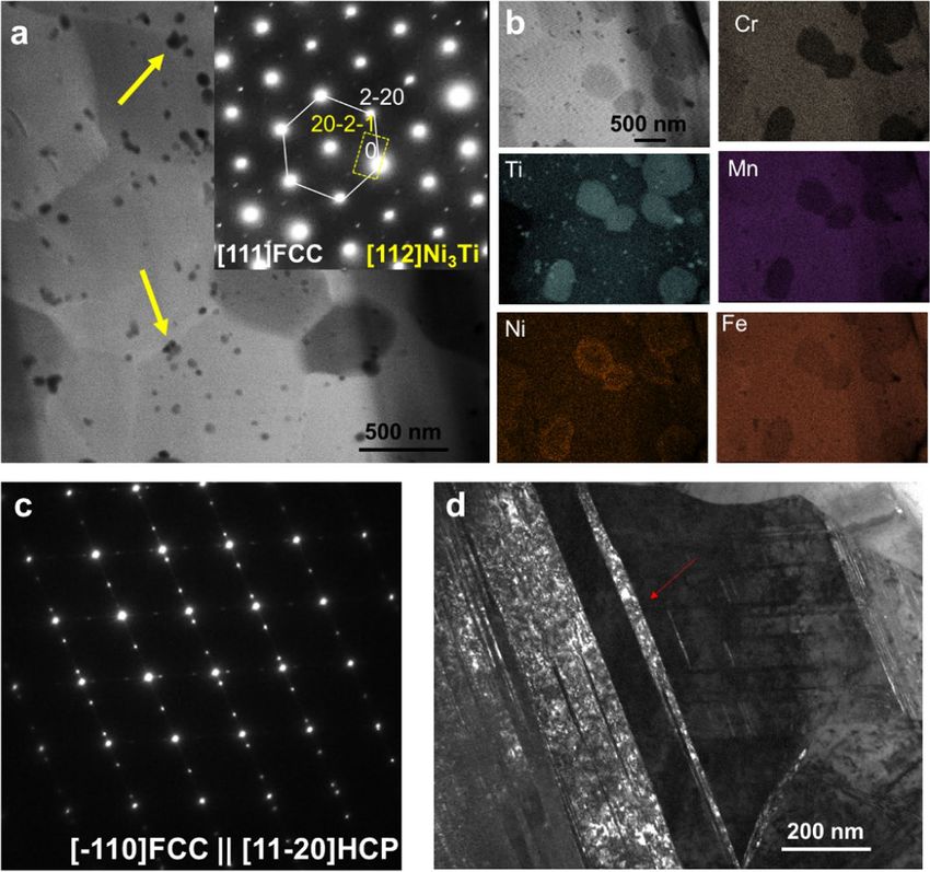
www.nature.com/scientificreports/
Figure 1. EBSD phase map and IPF map of (a1) as-cast and (a2) FSP specimen in undeformed condition; (b1)
engineering strain–stress and (b2) work hardening rate curves of as-cast and FSP specimens under quasi static
tensile testing load; EBSD phase map and IPF map of (c1) as-cast and (c2) FSP specimens in deformed condition.
Note that deformational twins are labelled by black arrows in (c2).
was used earlier during friction stir welding and processing where Cu14, and Fe15 powders were added during
the welding and processing of Al alloys, resulting in a homogeneous distribution of intermetallic precipitates and
thus enhancing mechanical properties of the processed zone. The FSA process used in the current work, utilizes
the shear deformation during the solid-state processing, to distribute the additional desired alloying element
into the matrix by non-equilibrium dissolution. Our previous work on non-equilibrium dissolution of Al into
Al0.1CoCrFeNi HEA m atrix16 and that of C
u17 and V 18 into TRIP HEA matrix via FSA produced encouraging
results and established the viability of this process. FSA is a more efficient way to develop new alloys, especially
for HEAs, since alloy modification on the existing material can be achieved without bulk melting, formation of
intermetallics and cracks. Furthermore, the microstructure after FSA (or any friction-stir-based technique) is
predominantly recrystallized and hence requires no further processing (such as rolling or heat-treatment), as
a result of the synergistic effects of strain, strain rate and temperature on microstructural modification. Note
that FSA is a local alloying technique which cannot produce bulk materials, but upscaling of such a process is
achievable by using the emerging friction-based manufacturing t echniques19.
In the current study, we selected Fe42.8Mn28.3Cr14.8Ni9.6Si4.5 at.% (Ni–Si5–HEA) as the starting material and
alloyed Ti using FSA. The alloying of Ti resulted in formation of Ni3Ti precipitates which, on one hand, strength-
ened the material; and, consequently, they also reduced Ni concentration around Ni3Ti precipitates, thus lowering
the SFE enough to introduce an additional TRIP mechanism effect locally.
Results and discussion
Benchmark from FSP. Figure 1(a1–a2) display the microstructural variation in as-cast and FSP conditions.
EBSD phase maps confirm that both as-cast and FSP conditions consist of a single phase of γ, which indicates
that no phase transformation occurred during FSP. Grain refinement was observed after FSP as the average grain
size of 13.7 ± 2.5 µm in as-cast condition reduced to 1.8 ± 0.6 µm in FSP condition. Mechanical behavior includes
Scientific Reports | (2021) 11:1579 | https://doi.org/10.1038/s41598-021-81350-0 2
Vol:.(1234567890)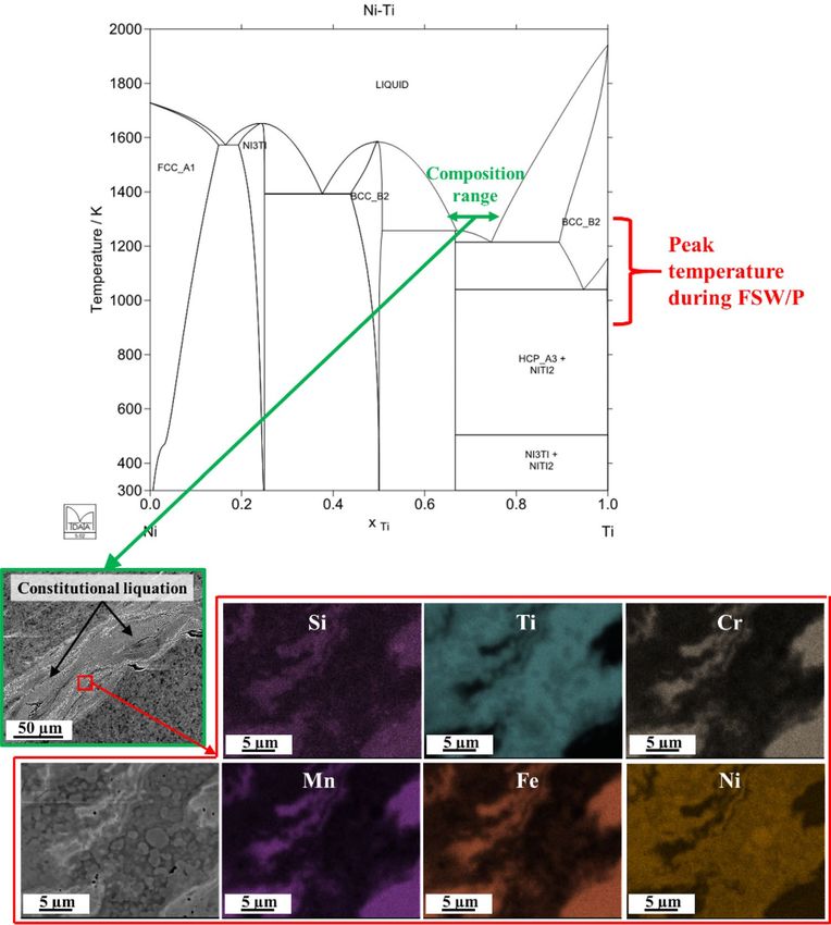
www.nature.com/scientificreports/

                                  Figure 2.  Phase diagram of Ni–Ti and SEM image and EDS map on processed region after one pass FSA
                                  displaying that constitutional liquation occurred during FSA.

                                  engineering stress–strain curves and work hardening rate of as-cast and FSP specimens (Fig. 1(b1–b2)). Yield
                                  strength, tensile strength and ductility increased from ~ 288 MPa, ~ 367 MPa and ~ 6% in the as-cast condition
                                  to ~ 451 MPa, ~ 645 MPa and ~ 43% in the FSP condition (Fig. 1(b1)). The decelerating trend in work hardening
                                  rate of FSP condition suggests that no phase transformation (TRIP) occurred during testing (Fig. 1(b2)). Also,
                                  there is no clear trend of work hardening rate of as-cast condition since it had limited ductility and early failure
                                  due to its coarse-grained structure (Fig. 1(b2)).
                                      Figure 1(c1,c2) display the microstructural response of as-cast and FSP specimens in deformed condition. Note
                                  that the scans were taken near the fracture tip. Phase maps of both as-cast and FSP conditions after deformation
                                  confirmed that no phase transformation had occurred, thereby indicating that TRIP had not occurred. In addi-
                                  tion, the inverse pole figure (IPF) maps of deformed FSP specimen show that deformation twins (labelled by
                                  black arrow in Fig. 1(c2)) formed during loading. While coarse grain size favors twinning, the lack of evidence
                                  of deformation twins in the deformed as-cast specimen might be due to the limited number of grains in the
                                  gauge section of the as-cast condition. Hence strain hardening behavior would be dependent on the orienta-
                                  tion of the individual grains with respect to the loading axis. For the present study, limited strain seems to have
                                  been accommodated by the as-cast microstructure by the onset of TWIP before crack and fracture. Therefore,
                                  improvement in mechanical properties of the FSP condition can be attributed to grain refinement and TWIP.

                                  Parameter optimization for FSA. We initially used a high tool rotation rate (600 RPM) to increase
                                  strain, strain rate and temperature in order to promote dissolution of Ti into the FCC matrix. However, some-
                                  what unexpectedly, excessive heat was produced during processing. Local melting of Ti was observed in the
                                  processed region (SEM images of Fig. 2). Previous studies confirmed that peak temperature during friction stir
                                  welding/processing on steels ranged from ~ 900 to 1300 K20–23. We assumed that the peak temperature during

Scientific Reports |   (2021) 11:1579 |                https://doi.org/10.1038/s41598-021-81350-0                                                   3

                                                                                                                                               Vol.:(0123456789)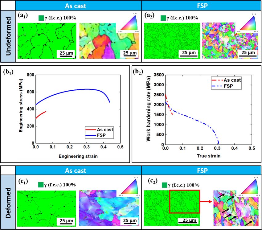
www.nature.com/scientificreports/
Condition Rotation rate (RPM) Traverse speed (mm/min)
FSP
First pass 650 50.8
Second pass 350 50.8
FSA
First pass 150 50.8
Second pass 150 50.8
Table 1. Critical process parameters applied for FSP and FSA process.
FSA of Ni–Si5–HEA would also fell in the same range since Fe content is near 40 at.% in the matrix. The peak
temperature during the FSA process being lower than the melting point of Ti by ~ 600–1000 K (phase diagram
in Fig. 2) implies that constitutional liquation occurred when Ti and Ni mixed in a certain compositional ratio
(composition range labelled in the phase diagram in Fig. 2).
Similar to observations in the present study, Sato et al.24 reported that constitutional liquation occurred
between friction stir welding (FSW) of aluminum and magnesium alloys at excessive temperatures. Therefore,
determining welding parameters that would generate lower heat during FSA is desirable. Previous research-
ers correlated the FSW parameters with non-dimensional peak temperature T *25 according to Eq. (1) and the
constants of α and β have been reported as 0.151 and 0.097, respectively, which fit well with various aluminum
alloys and steels based on the data reported i n26. Hence, we have assumed the values of these constants for our
HEA to be similar to the above-mentioned conventional alloys for this study.
T ∗ = αlog 10 (Q∗ ) + β (1)
* 25 *
The non-dimensional peak temperature, T , is defined in Eq. (2) . Q is the non-dimensional heat input defined
in Eq. (3)25.
TP − Tin
T∗ = (2)
Ts − Tin
σ8 AωCP φ
Q∗ = (3)
kU 2
where Tp is peak temperature, Tin is initial temperature and Ts is solidus temperature, σ8 is yield stress of the
P is the specific heat capacity, ϕ is the ratio
material at a temperature of 80% of solidus temperature of the material (0.8Ts), A is the cross-sectional area of
the tool shoulder, ω is tool rotational velocity, U is traverse speed, C
based on heat transfer between tool and workpiece, and k is thermal conductivity of the workpiece. Various
parameters and coefficients need to be provided to calculate actual peak temperature, T p, during FSW for a given
welding setup, including FSW tool dimensions, welding parameters and physical properties of the base material
and tool. If welding parameters are the only variables with constant FSW tool and base material properties, the
change in peak temperature can be simplified and calculated via Eq. (4), which was obtained through Eqs. (1)–(3).
ω(1)U(2)2
TP (1) − TP (2) = αlog 10 (Ts − Tin ) (4)
ω(2)U(1)2
We assumed the solidus temperature of the alloy ( TS) as ~ 1200 °C, and T
in equals 25 °C (ambient temperature).
By reducing the tool rotation rate (ω) from 600 to 150 RPM along with a constant traverse speed of 50.8 mm/
min, peak temperature reduced by ~ 130 °C. Combined with the fact that peak temperature during friction stir
welding/processing generally ranged from 900 to 1300 K, the peak temperature during optimized FSA process
(rotation rate of 150 RPM) is assumed to be lower than ~ 1200 °C (lower than constitutional liquation tempera-
ture of Ni–Ti system). Furthermore, the observation of no solidification features at 150 RPM indicated that the
reduction of peak temperature by 130 °C was sufficient to avoid constitutional liquation between Ti and Ni origi-
nating from Ni–Si5–HEA matrix during FSA. Therefore, two-pass FSA with tool rotation rate of 150 RPM was
conducted to dissolve Ti while avoiding constitutional liquation. EDS analysis was conducted on nugget region
of double-pass FSA condition to demonstrate element distribution (see Supplementary Fig. 2). Compared with
as-cast condition, elements of Cr, Mn. Fe and Ni are more homogenized, Si–Mn–Ni-rich phases were replaced
with much finer Si-rich phases, and Ti was dissolved into matrix in FSA condition.
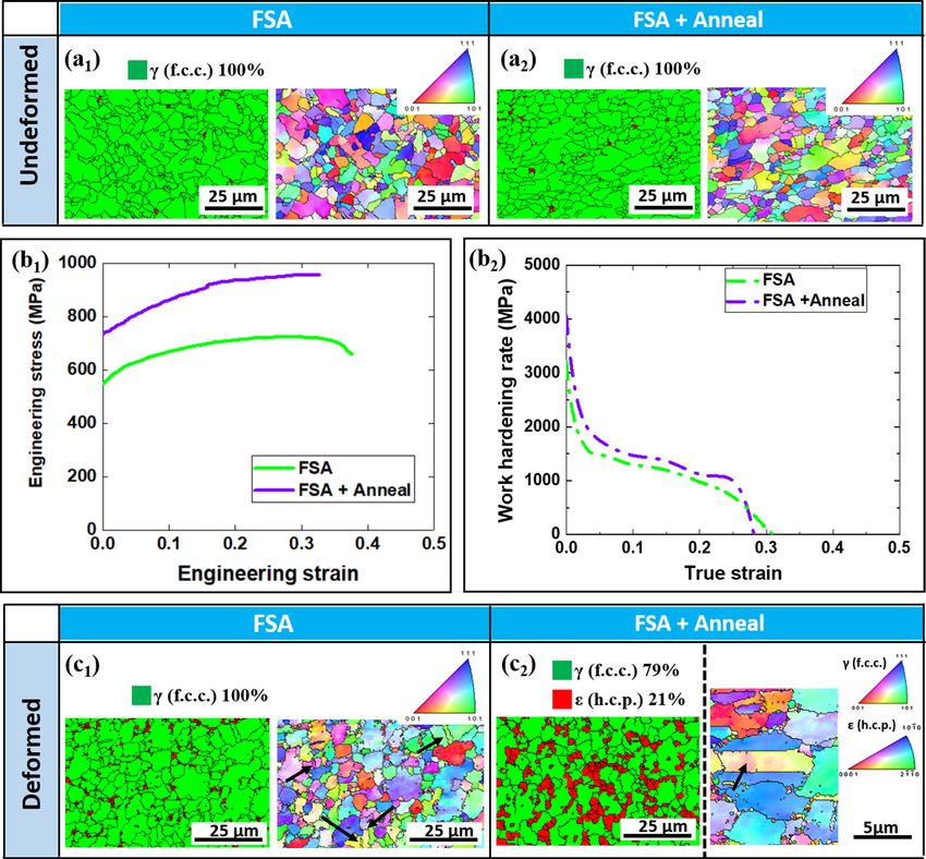
FSA and FSA + Anneal. FSA was conducted with optimized parameters as listed in Table 1. Then, micro-
structural analysis using orientation microscopy of before-and-after tensile testing was conducted on FSA speci-
mens (Fig. 3(a1,c1)). The phase map of the deformed FSA specimen did not show any significant evidence of
stress-induced phase transformation (TRIP effect); however, deformation twins (TWIP) can be observed in the
IPF map of the deformed FSA specimen (Fig. 3(c1)). Yield strength (~ 554 MPa) and tensile strength (~ 725 MPa)
of FSA specimens are both higher than the FSP condition. This is because the grain size (1.2 ± 0.5 µm) in the
FSA condition with lower rotation rate and heat input was finer than that in the FSP condition. A similar trend
Scientific Reports | (2021) 11:1579 | https://doi.org/10.1038/s41598-021-81350-0 4
Vol:.(1234567890)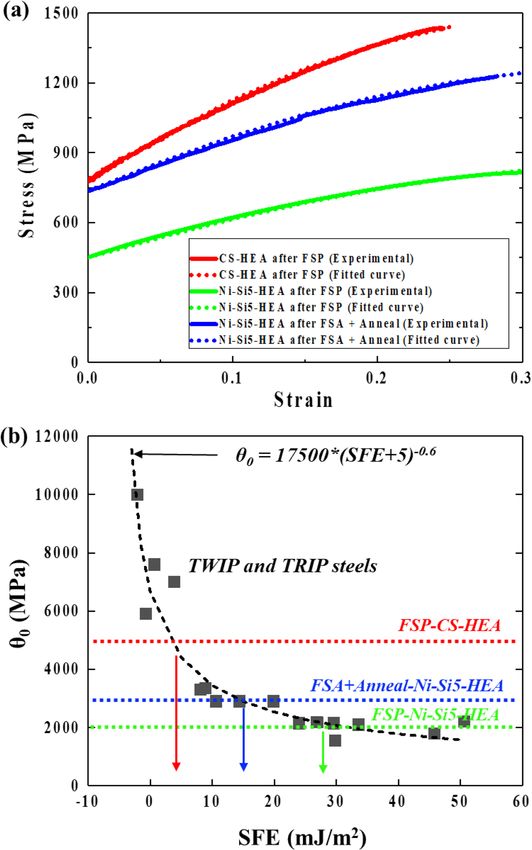
www.nature.com/scientificreports/
Figure 3. EBSD phase map and IPF map of (a1) FSA and (a2) FSA + Anneal specimens in undeformed
condition; (b1) engineering strain–stress and (b2) work hardening rate curves of FSA and FSA + Anneal
specimens under quasi static tensile testing load; EBSD phase map and IPF map of (c1) FSA and (c2)
FSA + Anneal specimens in deformed condition. Note that deformational twins are labelled by black arrows in
(c1 and c2). Also note that the red color displayed in phase map of (a1), (a2) and (c1) represent regions with low
confidence indexes values rather than ε (HCP) phases.
of work hardening rate in the FSA specimen as compared to the FSP specimen from tensile testing response
also suggests that TRIP was not triggered during testing of FSA specimens (Fig. 3(b2)). The additional annealing
step was done resulting in the precipitation of N
i3Ti phase as confirmed in Fig. 4(a). The precipitation of this
Ni enriched intermetallic phase may result in lowering of Ni concentration in the matrix surrounding these
precipitates. The reduction Ni concentration can result in lowering of the stacking fault energy of the matrix
and just increase the possibility of deformation by TRIP. Note that after annealing at 900 °C for 4 h, we did not
observe significant grain coarsening or phase changes in the microstructure (Fig. 3(a2)). Yield strength and
tensile strength of FSA + Anneal specimen are enhanced to ~ 736 MPa and ~ 958 MPa, respectively (Fig. 3(b1)).
Meanwhile, work hardening rate of the FSA + Anneal specimen being more sustained as compared with those of
FSA and FSP conditions (Fig. 3(b2)) suggests the possibility of an additional mechanism (TRIP) while deforma-
tion in the FSA + Anneal specimen during loading. Figure 3(c2) presents 21% of γ → ε transformation (TRIP)
and deformation twins (TWIP) of the FSA + Anneal specimen via EBSD phase map and IPF map, respectively.
To further substantiate the proposed hypothesis, a detailed TEM analysis of the final condition (i.e.,
FSA + Anneal) specimen was conducted. The results of both pre- and post-deformation TEM analyses are pre-
sented in Fig. 4. A high annular angle dark field scanning TEM (HAADF STEM) image of the pre-deformed
Scientific Reports | (2021) 11:1579 | https://doi.org/10.1038/s41598-021-81350-0 5
Vol.:(0123456789)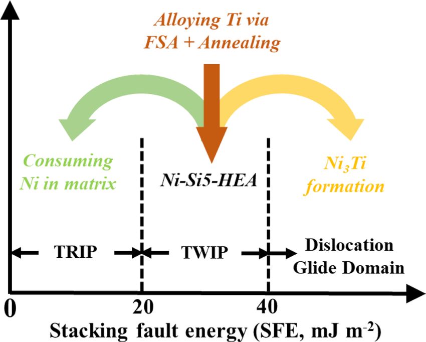
www.nature.com/scientificreports/
Figure 4. (a) HAADF-STEM image and corresponding SAED showing N i3Ti precipitates indicated via
yellow arrows after annealing and (b) corresponding TEM–EDS analysis revealing the presence of Ti and Ni
rich precipitates. (c) Post-deformation SAED indicating the orientation relationship between < 110 >fcc and
< 1120 >hcp and (d) BF-TEM showing transformation induced nano-scale HCP phases indicated via red
arrows.
sample shows the fine-grained structure with dark contrast precipitates (Fig. 4(a)). In addition to a high density
of extremely fine precipitates (~ 5 nm), some large second-phase grains were present. The corresponding selected
area electron diffraction (SAED) pattern was recorded along [ 111]FCC zone axis (Fig. 4 (a) inset). Note that the
extra reflections in the SAED pattern were consistently indexed to be [112] Ni3Ti phase based on a D024 structure.
The precipitates were further characterized using EDS. Precipitates rich in Ti and Ni were clearly visible in the
TEM–EDS analysis of the pre-deformed specimen (Fig. 4(b)), and hence the depletion of Ni from the matrix was
achieved via annealing treatment once the matrix was saturated with Ti during FSA. The evolution of deformation
structure on the tensile tested sample is presented in Fig. 4(c),(d). The SAED pattern of the deformed specimen
(Fig. 4(c)) clearly demonstrates a well-recognized orientation-relationship (OR) of FCC → HCP transformation,
also known as Shoji-Nishiyama OR, where < 110 >fcc is parallel to < 1120 >hcp. The corresponding dark field
TEM (DF-TEM) image in Fig. 4(d) also reveals the presence of HCP phase lamellae in FCC matrix. Previous
studies27–29 have established that in metastable FCC alloys, the formation of HCP lamellae is expected during
deformation. Hence, the final microstructural condition was tuned to demonstrate the deformation-induced
transformation of FCC to HCP phase.
A possible mechanism and procedure of FSA is summarized schematically in Fig. 5. Idrissi30 reported that
the activated plasticity mode is highly dependent on SFE values. With decreasing SFE, the observed defor-
mation mode is well-known to be transition from dislocation glide to mechanical twinning and finally to
martensitic phase t ransformation31. Generally, deformation-induced martensitic transformation is triggered
when SFE < 15 mJ m−232, mechanical twinning is triggered when 20 mJ m−2 < SFE < 40 mJ m−2, and disloca-
tion glide becomes the predominant plastic deformation mode when SFE > 40 mJ m−233. According to previous
literature30–33, SFE of Ni–Si5–HEA should lie within 20–40 mJ m−2, based on the absense of phase transformation
during straining. By introducing Ti into the system, Ni was preferentially depleted from the matrix. As a result,
local reduction in SFE was expected locally below 15–20 mJ m−2, enabiling the onset of TRIP during tensile
deformation. In addition to activation of TRIP as a strengthening mechanism, the newly-formed N i3Ti precipi-
tates also act as obstacles to dislocation glide during mechanical deformation. Meanwhile, TWIP was maintained
during mechanical deformation since a certain amount of Ni was left in the remaining matrix. Local changes
Scientific Reports | (2021) 11:1579 | https://doi.org/10.1038/s41598-021-81350-0 6
Vol:.(1234567890)www.nature.com/scientificreports/
Figure 5. Schematic showing the proposed tuning pathway via FSA.
are expected to have led to the changes deformation mechanisms, thus we evaluated the resultant deformation
behavior on work hardening behavior was observed to change.
To correlate the work hardening behavior, a strength model recently developed by Lloyd et al. was emploted
to correlate work hardening behavior with expected SFE. Four parameters were developed to model the strain
hardening behaviors of TRIP and TWIP s teels34. One of the four paramters θ0 was shown to be related to the
SFE, by the relationship shown in Eq. (5):
θ0 = 17500 × (SFE + 5.0)−0.6 (5)
Therefore, in this study, the four parameters of the model were tuned to fit the experimental stress–strain
behaviors of the FSP and the FSA + Anneal conditions of Ni–Si5–HEA. By comparison, another TRIP–HEA
(CS–HEA35) with similar chemical composition was also investigated. The experimental stress–strain curves
and fitting curves are shown in Fig. 6(a). θ0 for CS–HEA after FSP, Ni–Si5–HEA after FSP, and Ni–Si5–HEA
after FSA + Anneal is 5000, 2000 and 3000, respectively. Comparing θ0 of TRIP and TWIP HEAs with TWIP
and TRIP steels, the estimated SFE of Ni–Si5–HEA after FSP and FSA + Anneal are shown in Fig. 6(b). Note
that the estimated SFE of CS–HEA after FSP is between 0 and 10, which agrees with measured SFE of CS–HEA
though neutron d iffraction35.
Conclusions
A novel solid-state alloying method―friction stir alloying (FSA)―was applied to introduce Ti into a TWIP
HEA. The conclusions are:
• FSA parameter optimization was achieved by reducing tool rotation rate to 150 RPM Ni–Ti constitutional
liquation during FSA. Subsequently, Ti was successfully dissolved into the Ni–Si5–HEA matrix during FSA.
• Annealing of the FSA specimens led to the formation of Ni3Ti precipitates so that precipitation hardening
was introduced in this alloy system.
• Formation of N i3Ti precipitates facilitated a Ni-depleted region in the vicinity, which enabled TRIP locally.
• Transformation pathway under strain was modified from stand-alone TWIP in the base material to
TWIP + TRIP + PH in the FSA + Anneal specimen.
• Deformation behavior correlates well with SFE predicted by stress–strain response based on experimental
observations of TWIP and TRIP.
Materials and methods
Materials. The starting material is as-cast Ni–Si5–HEA ( Fe42.8Mn28.3Cr14.8Ni9.6Si4.5 at.%). The alloy was pro-
duced by vacuum arc-casting in a cold copper crucible, using pure metal powders and ingot dimensions of
300 × 100 × 6 mm3. The chamber was backfilled with argon to 1 atm. prior to each melt. The microstructure of
as-cast Ni–Si5–HEA is detailed in Supplementary Fig. 1. As-cast Ni–Si5–HEA consists of a single γ (FCC) phase
(Supplementary Fig. 1 (a)), but inhomogeneity in alloying elements exists. Apart from the matrix, Si–Mn–Ni-
rich and Cr–Fe-lean phases (labelled by yellow circles) and Cr-rich and Ni-lean phases (labelled by green circles)
were observed (Supplementary Fig. 1 (b)).
Methods. The influence of FSP and additional alloying of Ti were differentiated by stand-alone FSP on the
Ni–Si5–HEA (parameters listed in Table 1). As for the FSA process, pre-drilled holes of diameter 0.6 mm, depth
3.0 mm and gap 1.0 mm along the tool traverse direction were introduced via drilling on the as-cast Ni–Si5–
HEA sheet. Ti powders of 99.9% purity and ~ 10 µm average particle size were filled into these pre-drilled holes.
Note that the volume percentage of holes to processed region was ∼ 5%. According to the chemical composition
of base Ni–Si5–HEA (Fe42.8Mn28.3Cr14.8Ni9.6Si4.5 at.%), the density of base Ni–Si5–HEA is calculated as ~ 7.3 g/cc.
Scientific Reports | (2021) 11:1579 | https://doi.org/10.1038/s41598-021-81350-0 7
Vol.:(0123456789)www.nature.com/scientificreports/
Figure 6. (a) Experimental stress–strain curves of CS–HEA and Ni–Si5–HEA in different conditions, (b)
Correlations of θ0 and SFE for TRIP and TWIP steels.
The density of Ti is ~ 4.5 g/cc, therefore, the volume fraction of Ti being 5% can be transferred to be mass fraction
of Ti being ~ 3.1%. The nominal chemical composition of FSA (or FSA + Anneal) condition is: F e41.3 Mn27.3 Cr14.3
Ni9.3 Si4.3Ti3.5 at.%. Afterwards, the rotating tool traversed along the pre-drilled holes filled with Ti powders. The
parameters of FSA are also listed in Table 1. Differences in parameters between FSP and FSA are explained in
the section Parameter Optimization for FSA. A W–Re based tool was used for both FSP and FSA. Pin length,
pin diameter at root and tip, and shoulder diameter were 3.8 mm, 7.6 mm, 5.0 mm, and 16.0 mm, respectively.
Plunge depth is 4.0 mm for both FSP and FSA process. In addition, an annealing process was conducted on FSA
specimens so that N i3Ti precipitates formed along with the consumption of Ni in the matrix of the FSA speci-
men. Annealing temperature and time were 900 °C and 4 h, respectively.
Both microstructural evolution and mechanical behavior were included in this study. Transverse cross sec-
tions of processed volume were cut by electrical discharge machining and were final-polished to 0.02 µm surface
finish with colloidal silica suspension. Scanning electron microscopy (SEM), energy-dispersive X-ray spectros-
copy (EDS) and electron backscattered diffraction (EBSD) analyses were carried out using FEI Nova NanoSEM
230 with EDAX Octane Elite EDS and Hikari Super EBSD detector, respectively. The SEM imaging and EDS
analysis were performed at an accelerating voltage of 15 kV while EBSD analysis was performed with a step size
of 0.05 μm. Lift-out samples for transmission electron microscopy (TEM) were prepared using a FEI Nova 200
dual beam focused ion beam (FIB). TEM analysis was carried out on Tecnai G2 F20 S-Twin TEM operating at
200 kV. Mini-tensile testing on as-cast material, FSP and FSA specimens was conducted at initial strain rate of
0.001 s−1. Width, thickness and gauge length of the specimens were 1.0, 1.0, and 5.0 mm, respectively. Mini-
tensile specimens were taken from 1 mm below the surface of the processed nugget region. To maintain statistical
accuracy, three specimens were tested for each condition.
Scientific Reports | (2021) 11:1579 | https://doi.org/10.1038/s41598-021-81350-0 8
Vol:.(1234567890)www.nature.com/scientificreports/
Data availability
The raw/processed data required to reproduce these findings cannot be shared at this time as the data also forms
part of an ongoing study.
Received: 12 October 2020; Accepted: 4 January 2021
References
1. Yeh, J. et al. Nanostructured high-entropy alloys with multiple principal elements: novel alloy design concepts and outcomes. Adv.
Eng. Mater. 6(5), 299–303 (2004).
2. Tsai, M. & Yeh, J. High-entropy alloys: A critical review. Mater. Res. Lett. 2(3), 107–123 (2014).
3. Shukla, S., Wang, T., Cotton, S. & Mishra, R. S. Hierarchical microstructure for improved fatigue properties in a eutectic high
entropy alloy. Scr. Mater. 156, 105–109 (2018).
4. Li, Z., Pradeep, K. G., Deng, Y., Raabe, D. & Tasan, C. C. Metastable high-entropy dual-phase alloys overcome the strength–ductility
trade-off. Nature 534(7606), 227 (2016).
5. Sinha, S. et al. Microstructural evolution and deformation behavior of Ni–Si- and Co–Si-containing metastable high entropy alloys.
Metall. Mater. Trans. A https://doi.org/10.1007/s11661-018-4968-6 (2018).
6. Su, J., Raabe, D. & Li, Z. Hierarchical microstructure design to tune the mechanical behavior of an interstitial TRIP-TWIP high-
entropy alloy. Acta Mater. 163, 40–54 (2019).
7. Li, Z., Tasan, C. C., Springer, H., Gault, B. & Raabe, D. Interstitial atoms enable joint twinning and transformation induced plasticity
in strong and ductile high-entropy alloys. Nat. Publ. Gr. https://doi.org/10.1038/srep40704 (2017).
8. He, J. Y. et al. A precipitation-hardened high-entropy alloy with outstanding tensile properties. Acta Mater. 102, 187–196 (2016).
9. Nene, S. S. et al. Extremely high strength and work hardening ability in a metastable high entropy alloy. Sci. Rep. 8(1), 9920 (2018).
10. Charnock, W. & Nutting, J. The effect of carbon and nickel upon the stacking-fault energy of iron. Met. Sci. J. 1(1), 123–127 (1967).
11. Liu, S. F. et al. Stacking fault energy of face-centered-cubic high entropy alloys. Intermetallics 93, 269–273 (2018).
12. Zaddach, A. J., Niu, C., Koch, C. C. & Irving, D. L. Mechanical properties and stacking fault energies of NiFeCrCoMn high-entropy
alloy. JOM 65(12), 1780–1789 (2013).
13. Mishra, R. S. & Ma, Z. Y. Friction stir welding and processing. Mater. Sci. Eng. R Rep. 50(1–2), 1–78 (2005).
14. Inada, K., Fujii, H., Ji, Y. S., Sun, Y. F. & Morisada, Y. Effect of gap on FSW joint formation and development of friction powder
processing. Sci. Technol. Weld. Join. 15(2), 131–136 (2010).
15. Fujii, H. et al. Fabrication of Fe-based metallic glass particle reinforced Al-based composite materials by friction stir processing.
Mater. Trans. 52(8), 1634–1640 (2011).
16. Wang, T., Shukla, S., Komarasamy, M., Liu, K. & Mishra, R. S. Towards heterogeneous AlxCoCrFeNi high entropy alloy via friction
stir processing. Mater. Lett. 236, 472–475 (2019).
17. Shukla, S. et al. Friction stir gradient alloying: A novel solid-state high throughput screening technique for high entropy alloys.
Mater. Today Commun. 23, 100869 (2019).
18. Agrawal, P., Shukla, S., Gupta, S., Agrawal, P. & Mishra, R. S. Friction stir gradient alloying: a high-throughput method to explore
the influence of V in enabling HCP to BCC transformation in a γ-FCC dominated high entropy alloy. Appl. Mater. Today 21,
100853 (2020).
19. Yu, H. Z. & Mishra, R. S. Additive friction stir deposition: a deformation processing route to metal additive manufacturing. Mater.
Res. Lett. 9(2), 71–83 (2020).
20. Nandan, R. G. G. R., Roy, G. G., Lienert, T. J. & Debroy, T. Three-dimensional heat and material flow during friction stir welding
of mild steel. Acta Mater. 55(3), 883–895 (2007).
21. Fujii, H. et al. Friction stir welding of carbon steels. Mater. Sci. Eng. A 429(1–2), 50–57 (2006).
22. Tungala, V. et al. Microstructure and mechanical properties of friction stir processed cast Eglin steel (ES-1). Mater. Sci. Eng., A
709, 105–114 (2018).
23. Manvatkar, V., De, A., Svensson, L. E. & DebRoy, T. Cooling rates and peak temperatures during friction stir welding of a high-
carbon steel. Scr. Mater. 94, 36–39 (2015).
24. Sato, Y. S., Park, S. H. C., Michiuchi, M. & Kokawa, H. Constitutional liquation during dissimilar friction stir welding of Al and
Mg alloys. Scr. Mater. 50(9), 1233–1236 (2004).
25. Roy, G. G., Nandan, R. & DebRoy, T. Dimensionless correlation to estimate peak temperature during friction stir welding. Sci.
Technol. Weld. Join. 11(5), 606–608 (2006).
26. Arora, A., DebRoy, T. & Bhadeshia, H. K. D. H. Back-of-the-envelope calculations in friction stir welding–velocities, peak tem-
perature, torque, and hardness. Acta Mater. 59(5), 2020–2028 (2011).
27. Yang, J. X., Zhao, H. L., Gong, H. R., Song, M. & Ren, Q. Q. Proposed mechanism of HCP→ FCC phase transition in titianium
through first principles calculation and experiments. Scientific Reports 8(1), 1–9 (2018).
28. Miao, J. et al. The evolution of the deformation substructure in a Ni–Co–Cr equiatomic solid solution alloy. Acta Mater. 132, 35–48
(2017).
29. Niu, C., LaRosa, C. R., Miao, J., Mills, M. J. & Ghazisaeidi, M. Magnetically-driven phase transformation strengthening in high
entropy alloys. Nat. Commun. 9(1), 1–9 (2018).
30. Idrissi, H., Ryelandt, L., Veron, M., Schryvers, D. & Jacques, P. J. Is there a relationship between the stacking fault character and
the activated mode of plasticity of Fe–Mn-based austenitic steels?. Scr. Mater. 60(11), 941–944 (2009).
31. Curtze, S. & Kuokkala, V. T. Dependence of tensile deformation behavior of TWIP steels on stacking fault energy, temperature
and strain rate. Acta Mater. 58(15), 5129–5141 (2010).
32. De Cooman, B. C., Estrin, Y. & Kim, S. K. Twinning-induced plasticity (TWIP) steels. Acta Mater. 142, 283–362 (2018).
33. Allain, S., Chateau, J. P., Bouaziz, O., Migot, S. & Guelton, N. Correlations between the calculated stacking fault energy and the
plasticity mechanisms in Fe–Mn–C alloys. Mater. Sci. Eng. A 387, 158–162 (2004).
34. Lloyd, J. T., Field, D. M. & Limmer, K. R. A four parameter hardening model for TWIP and TRIP steels. Mater. Des. 194, 108878
(2020).
35. Frank, M. et al. Investigating the deformation mechanisms of a highly metastable high entropy alloy using in-situ neutron diffrac-
tion. Mater. Today Commun. 23, 100858 (2020).
Acknowledgements
The work was performed under a cooperative agreement between the Army Research Laboratory and the Uni-
versity of North Texas (W911NF-18-2-0067) and the National Science Foundation (NSF) Grant 1435810. The
authors acknowledge Materials Research Facilities (MRF) at University of North Texas for the use of microscopy
equipment.
Scientific Reports | (2021) 11:1579 | https://doi.org/10.1038/s41598-021-81350-0 9
Vol.:(0123456789)www.nature.com/scientificreports/
Author contributions
R.S.M. designed the work. T.W. and S.S. conducted the processing and heat treatment experiments. S.S. and B.G.
conducted the TEM experiments and analyzed the data. S.S. conducted the EBSD experiments and analyzed the
data. S.T. and M.F. conducted the mechanical testing experiments and analyzed the data. T.W., S.S., B.G. and
R.S.M. drafted the manuscript and all the authors contributed to the final paper.
Competing interests
The authors declare no competing interests.
Additional information
Supplementary Information The online version contains supplementary material available at https://doi.
org/10.1038/s41598-021-81350-0.
Correspondence and requests for materials should be addressed to R.S.M.
Reprints and permissions information is available at www.nature.com/reprints.
Publisher’s note Springer Nature remains neutral with regard to jurisdictional claims in published maps and
institutional affiliations.
Open Access This article is licensed under a Creative Commons Attribution 4.0 International
License, which permits use, sharing, adaptation, distribution and reproduction in any medium or
format, as long as you give appropriate credit to the original author(s) and the source, provide a link to the
Creative Commons licence, and indicate if changes were made. The images or other third party material in this
article are included in the article’s Creative Commons licence, unless indicated otherwise in a credit line to the
material. If material is not included in the article’s Creative Commons licence and your intended use is not
permitted by statutory regulation or exceeds the permitted use, you will need to obtain permission directly from
the copyright holder. To view a copy of this licence, visit http://creativecommons.org/licenses/by/4.0/.
© The Author(s) 2021
Scientific Reports | (2021) 11:1579 | https://doi.org/10.1038/s41598-021-81350-0 10
Vol:.(1234567890)You can also read