APPENDIX 11 TO THE GENERAL CONTRACT OF USE FOR WAGONS - INSCRIPTIONS AND SIGNS ON WAGONS - GCU - Bureau
←
→
Page content transcription
If your browser does not render page correctly, please read the page content below
GENERAL CONTRACT OF USE FOR WAGONS                         APPENDIX 11

                                     APPENDIX 11
       TO THE GENERAL CONTRACT OF USE FOR WAGONS

                        INSCRIPTIONS AND SIGNS ON WAGONS

Version: 1-jan-2021                                                 1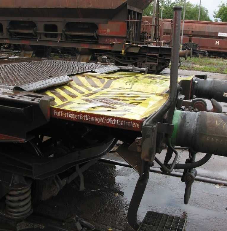
GENERAL CONTRACT OF USE FOR WAGONS                                                                          APPENDIX 11
Contents

Point    Subject                                                                                                   Page
1        Introduction – General provisions                                                                         4
2.1      Wagon number, country of registration, keeper, type                                                       5
2.2      Derogation plate                                                                                          7
2.3      Maintenance plate                                                                                         9
2.4      Signs indicating load limits                                                                              10
2.5      Sign indicating carrying capacity                                                                         12
2.6      Signs indicating concentrated loads distributed over supporting surfaces of different lengths             13
2.7      Sign indicating the capacity of tank wagons and cask wagons                                               17
2.8      Signs indicating the length of load and floor space                                                       18
2.9      Sign indicating the distance between end axles and bogie centres                                          19
2.10     Sign indicating spark arrestor plates                                                                     19
2.11     Additional signs for wagons authorised to run in Great Britain                                            21
2.12     Sign for ferry ramp angle                                                                                 22
2.13     Sign for removable wagon accessories                                                                      23
2.14     Sign for the inside of wagons: "Do not use nails or wire staples"                                         25
2.15     Marking for wagons with special fittings (wagons with automatic discharge facility, opening roof, etc.)   25
2.16     Signs for wagons built for running between countries with different track gauges                          26
2.17     Sign for bogies fitted with gauge-adjustable axles, nominal gauge 1435 mm (automatic gauge
                                                                                                    26
         changeover facility according to the UIC leaflet 510-4)
2.18     Sign for bogies fitted with gauge-adjustable axles, nominal gauge 1520 mm (automatic gauge
                                                                                                    27
         changeover facility according to the UIC leaflet 510-4)
2.19     Additional signs for wagons accepted for running in Spain and Portugal                                    28
2.20     Approval plate                                                                                            29
2.21     Marking of vehicle gauge on wagon                                                                         29
3.1      Sign for height of the loading plane for container wagons in unladen state                                30
3.2      Signs for combined transport wagons in accordance with UIC leaflet 50571-4                                31
4.1      Sign for length over buffers                                                                              38
4.2      Signs for tare and braked weight                                                                          39
4.3      Signs to indicate the changeover device for air brakes - Marking of the braked weight on wagons.
                                                                                                          41
         Brake type abbreviations
4.4      Signs for wagons fitted with composite brake blocks                                                       48
4.5      Sign for wagons fitted with disc brakes                                                                   49
5.1      Sign for wagons not authorised to negotiate all shunting humps                                            50
5.2      Sign for bogie wagons with a distance of over 14.0 m between inner axles and accepted on shunting
                                                                                                           50
         humps
5.3      Sign for wagons that are not authorised to pass through retarders or other shunting and stopping
                                                                                                          51
         devices in active mode
5.4      Sign for wagons not to be loose-shunted                                                                   51
5.5      Sign for wagons that must not be fly- or gravity-shunted                                                  52
5.6      Sign for fly and hump shunting not permitted for containers or loaded pocket wagons                       52
5.7      Marking for wagons fitted with anti-crash components                                                      53

Version: 1-jan-2021                                                                                                     2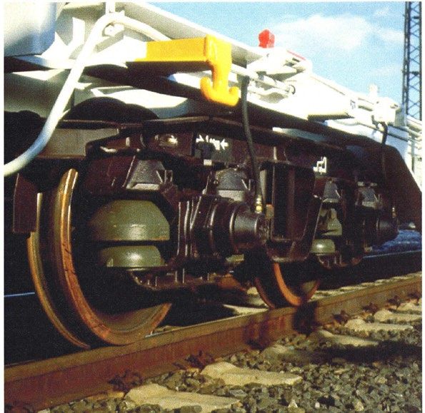
GENERAL CONTRACT OF USE FOR WAGONS                                                                         APPENDIX 11

Point    Subject                                                                                                Page
5.8      Marking for wagons fitted with long-stroke shock absorbers (schock absorber fitting)                   53
5.9      Marking for wagons fitted with projecting tow hooks                                                    54
5.10     Sign for permanently-coupled wagon units                                                               54
5.11     Sign for bogie wagons only able to negotiate curves with a radius greater than 35 m                    55
5.12     Signs indicating wagons fitted with a train line                                                       55
5.13     Sign for wagons fitted with the automatic coupler                                                      56
5.14     Sign for derailment detectors                                                                          56
5.15     Sign for strengthened screw coupling                                                                   57
6.1      Sign for wheels able to withstand high thermal stresses                                                59
6.2      Marking of tyred wheels                                                                                59
6.3      Sign for ventilation pipes                                                                             60
6.4      Sign for tank wagon tests, coding of tanks and special regulations                                     60
7.1      Sign indicating points for lifting the wagon body in the workshop                                      61
7.2      Sign for lifting at 4 points with or without running gear                                              61
7.3      Sign for lifting or re-railing with or without running gear at one end only or close to the end        62
7.4      Sign for the replacement of springs                                                                    62
7.5      Sign Wheel tyre inspection                                                                             63
7.6      Sign for inspection periods for temperature controlled units                                           64
7.7      Sign for the protection of the inner lining of tank wagons                                             64
7.8      Signs for privately-owned wagons, unified wagons, standard wagons                                      65
7.9      Sign for the spare parts                                                                               66
8.1      Signs for high voltage warning sign                                                                    67

Version: 1-jan-2021                                                                                                  3
GENERAL CONTRACT OF USE FOR WAGONS                                                      APPENDIX 11

1       Introduction – General provisions

1.1     This appendix describes the inscriptions and signs to be affixed to freight wagons
        (referred to hereafter as wagons) and indicates where they should be positioned. The
        inscriptions and signs have been grouped together according to certain processes or
        operations: the loading and provision of wagons, combined transport (CT), train
        preparation, shunting, technical inspections, workshops and key warning signs – but are
        not exclusively assigned to a specific process, specialist department or user.

1.2     Wagons must carry inscriptions and signs in specific places. They should be affixed in the
        language of the wagon keeper, using Latin characters and Arabic numerals.
        The inscriptions and signs must always be clearly visible. They should be placed on the
        side walls, if possible 1600 mm above rail level (height of the middle of the sign).
        For wagons without side walls, the inscriptions shall be carried on special boards. For the
        provisions regarding the mark plates on the tank wagons see UIC leaflet 573.
        No other meanings may be assigned to the inscriptions and signs.

1.2     Wagons on which the markings and signs are missing or illegible shall be dealt with in
        accordance with Annexes 9 and 10.

1.4     Inscriptions and signs other than those listed in this annex must be placed on parts of the
        wagon not occupied by these inscriptions.
        The lower left-hand corner of the side walls is reserved for affixing labels, with the
        exception of K and M labels.

Version: 1-jan-2021                                                                              4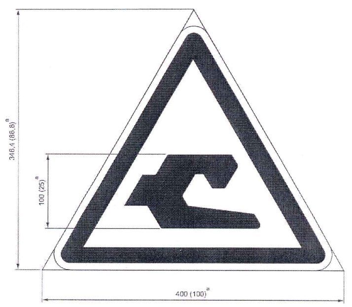
GENERAL CONTRACT OF USE FOR WAGONS                                                             APPENDIX 11
2.1     Wagon number, country of registration, keeper, type

The markings shall be made on the side of the wagon as follows (examples):

                      31      RIV            32    RIV            33      RIV            43
                      80      D-DB           80    D-BASF         84      NL-ACTS        87     F
                      0691 235-2             7369 553-4           4796 100-8             4273 361-3
                      Tanoos                 Zcs                  Slpss                  Laeks

or

                      33      TEN           87     TEN
                      84      NL-ACTS       82     D-CFLCA
                      4796 100-8            4978 006-4
                      Slpss                 Sdmrs
                                     G1                   CW
or
                      37      TEN           81     TEN
                      82      L-CFLCA       82     L-CFLCA
                      4992 009-1            3513 156-7
                      Sdggmrss GE           Rbnpss     Derogation plate

When the wagon body does not provide sufficient surface area for this layout (flat wagons in
particular) the markings shall be made as follows (example):
                      01 87                3320 644-7
                      RIV F-SNCF           Ks

Position: on the left of each side wall, or the left of each solebar in the case of high-sided open
wagons or on special boards in the case of wagons without side walls (e.g. tank wagons).
Meaning (based on the first example):
      31              Fitness for interoperability (2 digits)
      80              Country in which the wagon is registered (2 digits)
      0691            Principal technical characteristics (4 digits)
      235             Number of the wagon in its production series (3 digits)
      -2              Self-check digit (1 digit)
      RIV             The RIV marking on wagons means that the vehicle, in addition to having been
                      approved against the rules in force, also meets the regulations of railway
                      Technical Unity (TU) and the provisions of leaflets in the UIC Code and, as a
                      result, satisfies all regulations applicable for its respective type in international
                      rail traffic. These wagons are fully interoperable.
      TEN             New wagons which have obtained approval against the TSIs (Technical
                      Specifications for Interoperability). The letters TEN (for Trans-European
                      Network) may also appear alongside the RIV marking or additional markings
                      indicating the vehicle gauge.
      D               Country in which the wagon is registered, in this case Germany

Version: 1-jan-2021                                                                                      5
GENERAL CONTRACT OF USE FOR WAGONS                                                     APPENDIX 11
     DB           Wagon keeper (abbreviation); this information is compulsory if the full name of
                  the company complete with address is not given.
        Tanoos        Reference to principal technical characteristics of the vehicle:
                      - T: Letter indicating wagon type (capital letter)
                      - anoos: identification letters; lower-case letters describing the principal features
                        for the use of the wagon

N.B.:
     1.    Further details are given in the Uniform Technical Prescription applicable to Vehicle
           Numbers and linked alphabetical marking on the bodywork: The Railway Vehicle
           Marking (UTP Marking), issued by the OTIF.
     2.    Wagons with more than 8 axles can still carry the RIV sign without satisfying the
           regulations on maximum load (see point 2.4) provided they meet all the other conditions
           of this appendix and of Appendix 9 and have no parts that are liable to encroach the
           vehicle gauge under any operating circumstances. Exceptions are authorised for these
           wagons in respect of the position of the markings.
     3.** For wagons meeting all the requirements of the Wagons TSI WAG, the pictogram

           is used in conjunction with characters 2 or 3 of the wagon number and the "TEN"
           marking.
     4.** For wagons which are basically TSI WAG-compliant but which deviate in terms of their
          wheelbase or vehicle gauge, or which are subject to other operating restrictions when
          used in wagonload traffic, the pictogram

           is used in conjunction with characters 4 or 8 of the wagon number and the "TEN"
           marking. In terms of their initial approval for placing in service, these wagons are subject
           to the conditions in force in all member states; however, under the OPE TSI specific
           agreements are to be concluded governing their use on individual member-state
           infrastructure.

**        Official part of GCU on 1 March 2014 due to voting and adoption procedure of the GCU.

Version: 1-jan-2021                                                                                      6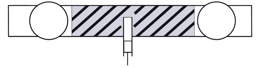
GENERAL CONTRACT OF USE FOR WAGONS   APPENDIX 11

2.2     Derogation plate

Figure 1

Figure 2

Version: 1-jan-2021                           7
GENERAL CONTRACT OF USE FOR WAGONS                                                    APPENDIX 11

Figure 3

Figure 4

Position:       On the right of each side wall.

Meaning:        Because they do not comply fully with the UIC Code, these wagons are not
                marked with the “RIV” sign. Their use is therefore subject to bi- or multilateral
                agreements between RUs. The initials of the parties to these agreements are
                entered in this box and these wagons may only be used by the RUs indicated. As
                such, they are not fully interoperable.
                The letters GA or GB indicate the gauge to which the wagons were built, as
                described in UIC leaflet 506

Version: 1-jan-2021                                                                            8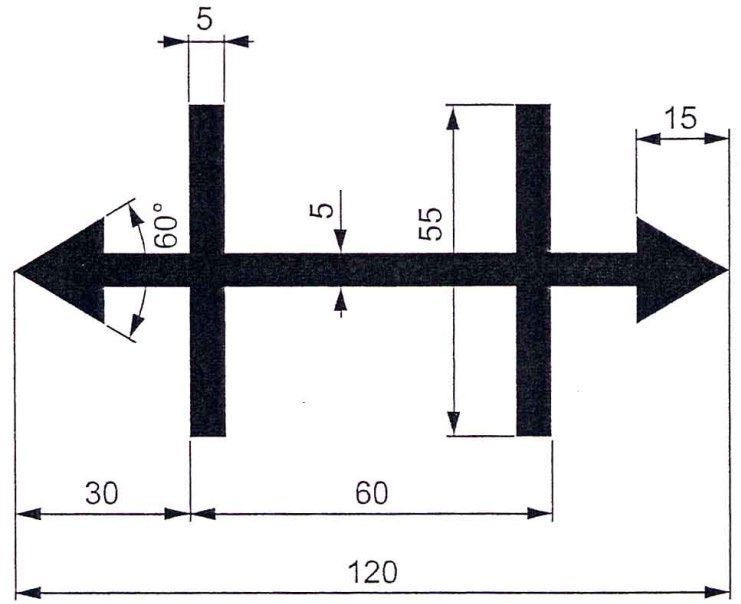
GENERAL CONTRACT OF USE FOR WAGONS                                                              APPENDIX 11

2.3      Maintenance plate

Figure 1

Figure 2

Position:      In the middle of each solebar, or on the parts covering the solebar or on special
               boards fixed at the same height.
Meaning:       From this day, plus the extended validity period of 3 months if duly indicated, the
               wagon formally loses its autorisation to run in normal service.

1)    Maintenance plate validity period: see Appendix 10, paragraph C, point 1 or 1.1 for additional details
2)    Identification mark of the workshop that carried out the maintenance work.
3)    Date on which the work was carried out (day, month, year).
4)    Additional marking in accordance with Appendix 10, paragraph C, point 1.2. To be applied only on the
      instructions of the keeper.

Version: 1-jan-2021                                                                                       9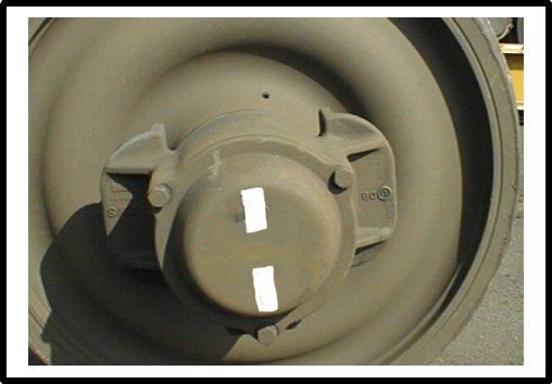
GENERAL CONTRACT OF USE FOR WAGONS     APPENDIX 11

2.4     Signs indicating load limits
Figure 1

Figure 2

Figure 3

Figure 4

Figure 5

Figure 6

Figure 7

Version: 1-jan-2021                            10
GENERAL CONTRACT OF USE FOR WAGONS APPENDIX 11
Figure 8
Figure 9*
Figure 10*
* As an exception to this rule, the stars may also be positioned to the left of the load limit panel.
Position: On the left of each side wall.
Meaning: S Maximum load in t (tonnes) for wagons running in trains operated
under S conditions (maximum speed 100 km/h) with no particular
operating restrictions.
SS Maximum load in t (tonnes) for wagons running in trains operated under
SS conditions (maximum speed 120 km/h) with no particular operating
restrictions.
120/00,0 Wagons only authorised to run in trains up to 120 km/h when
empty (figures 3 and 9).
Fig. 4, 5 Maximum load in t (tonnes) and maximum speed (in km/h) agreed
between RUs and exceeding the load limit set out in the UIC Code.
Maximum load in t (tonnes) for wagons authorised to run in trains up to
120 km/h with a brake that does not meet all the requirements for SS
conditions.
*) Maximum load in t (tonnes) for wagons authorised to run in trains up to
120 km/h with a brake that does not meet all the requirements for SS
conditions. The wagons must be fitted with an automatic load-
proportional braking system.
N.B. 1: Wagons should only carry the markings for line category D if, for that category of
line, they can accommodate a higher maximum axle-load than for category C.
Wagons should only carry the markings for line category E if, for that category of
line, they can accommodate a higher maximum axle-load than for category D.
N.B. 2: For wagons carrying the and signs, RUs shall define the necessary
rules for the correct formation of the train (achieving the right brake percentage,
timetable changes where appropriate, etc.).
*) Marking *** for all new wagons meeting the corresponding conditions entering service from
1.1.2007.
Version: 1-jan-2021 11GENERAL CONTRACT OF USE FOR WAGONS APPENDIX 11
2.5 Sign indicating the carrying capacity
Position: On the right of each solebar, or on parts covering the solebar or on special
boards fitted at the same height as the solebars
Meaning: Sign for wagons with a carrying capacity that is greater than the maximum load
marked, and for wagons with no maximum load marking [t].
Version: 1-jan-2021 12GENERAL CONTRACT OF USE FOR WAGONS APPENDIX 11
2.6 Signs indicating concentrated loads distributed over supporting surfaces of
different lengths
2.6.1 Example of concentrated loads spread over supporting surfaces of different lengths and
loads resting on two separate points (width of bearing surface ≥ 2 m)
Markers on solebars
Maximum value for different lengths:
Maximum valueloads
- of concentrated for different
spreadlengths:
over the lengths of the supporting surface
- of concentrated loads spread over the lengths of the supporting surface
- of loads resting on two supporting points
- of loads resting on two supporting points
1) Indication of the length of the supporting surfaces of the concentrated loads or distance between
supporting points.
2) Distance, in metres, between the length markers.
3) Maximum value, in tonnes, of the concentrated loads.
4) Maximum value, in tonnes, of loads resting on two supporting points.
Position: In the middle of each solebar, or on parts covering the solebar or on special
boards fitted at the same height as the solebars.
Meaning: See point 2.6.2
Version: 1-jan-2021 13GENERAL CONTRACT OF USE FOR WAGONS APPENDIX 11
2.6.2 Example of concentrated loads distributed over supporting surfaces of different length and
loads resting on two separate points (width of bearing surface ≥ 1.20 m)
Markers on solebars
Maximum value for different lengths:
- of concentrated loads spread over the lengths of the supporting surface
- of loads resting on two supporting points
1) Indication of the length of the supporting surfaces of the concentrated loads or distance between
supporting points.
2) Distance, in metres, between the length markers.
3) Maximum value, in tonnes, of the concentrated loads.
4) Maximum value, in tonnes, of loads resting on two supporting points
Position: In the middle of each solebar, or on parts covering the solebar or on special
boards fitted at the same height as the solebars.
Meaning of the On unified flat wagons, this sign indicates the maximum values for concentrated
figures shown in loads and loads resting on 2 supporting points according to the stated values
points 2.6.1 and for the length of supporting surfaces and distances in the UIC Code. This sign
2.6.2: is optional for:other wagons which may, if required, carry the sign specified
inpoints 2.6.1 or 2.6.2 or 2.6.3 or 2.6.4.
Version: 1-jan-2021 14GENERAL CONTRACT OF USE FOR WAGONS APPENDIX 11
2.6.3 Example of concentrated loads distributed over supporting surfaces of different length
(width of bearing surface ≥ 2 m)
Markers on solebars
3
Maximum value for different lengths:
- of concentrated loads spread over the lengths of the supporting surface
1) Indication of the length of the supporting surfaces of the concentrated loads or distance between
supporting points.
2) Distance, in metres, between the length markers.
3) Maximum value, in tonnes, of the concentrated loads.
Position: In the middle of each solebar, or on parts covering the solebar or on special
boards fitted at the same height as the solebars.
Meaning: See point 2.6.4.
Version: 1-jan-2021 15GENERAL CONTRACT OF USE FOR WAGONS APPENDIX 11
2.6.4 Example of concentrated loads distributed over supporting surfaces of different length
(width of bearing surface ≥ 1.20 m)
Markers on solebars
Maximum value for different lengths:
- of concentrated loads spread over the lengths of the supporting surface
1) Indication of the length of the supporting surfaces of the concentrated loads or distance between
supporting points.
2) Distance, in metres, between the length markers.
3) Maximum value, in tonnes, of the concentrated loads.
Position: In the middle of each solebar, or on parts covering the solebar or on special
boards fitted at the same height as the solebars.
Meaning of the For flat wagons not covered by points 2.6.1 and 2.6.2, with a loading plane
figures shown in more than 10 m long, and high-sided open wagons built after 1 January 1968,
points 2.6.3 and this sign indicates the maximum value for concentrated loads spread over
2.6.4: supporting surfaces for at least three different lengths. This sign is optional for
other wagons.
Version: 1-jan-2021 16GENERAL CONTRACT OF USE FOR WAGONS APPENDIX 11
2.7 Sign indicating the capacity of tank wagons and cask wagons
Position: On the left of each side wall; for tank wagons, on the tank itself or on special
boards.
Meaning: Capacity in m3, hl or l
For tank wagons, this sign should also specify the commodities that the vehicle is
authorised to carry, if required by the RID for the carriage of dangerous goods.
Version: 1-jan-2021 17GENERAL CONTRACT OF USE FOR WAGONS APPENDIX 11
2.8 Signs indicating the length of load and floor space
Figure 1 Length of load
Position: On the left of each side wall.
Meaning: Loading length in [m] for flat wagons and covered wagons with a flat floor, minus
the thickness of any intermediate partitions (useful length).
Figure 2 Floor space
Position: On the left of each side wall.
Meaning: Surface area [m2] of the floor of covered wagons and wagons with an opening
roof and flat floor.
Version: 1-jan-2021 18GENERAL CONTRACT OF USE FOR WAGONS APPENDIX 11
2.9 Sign indicating the distance between end axles and bogie centres
Position: On the right of each solebar, or on the bogie frame (it is sufficient for the sign to
feature on the left-hand side of the bogie, on each side of the wagon) or on parts
covering the solebar or on special boards fitted at the same height as the
solebars.
Meaning: Indicates the distance:
- between the end axles of bogies and of wagons other than bogie wagons,
- between the bogie centres of bogie wagons.
2.10 Sign indicating spark arrestor plates
White
Position: In the middle of each solebar, or on parts covering the solebar or on special
boards fitted at the same height as the solebars. This sign may also be affixed on
the right of each side wall.
Meaning: Wagon fitted with spark-arrestor plates in accordance with Appendix A to UIC
leaflet 543; these plates are required for axle wagons suitable for carrying class
1 commodities, sub-classes 1.1, 1.2, 1.3, 1.5 and 1.6, as well as certain
commodities in classes 4.1 and 5.1 (RID, Part 7, points 7.2.4 and W 8).
Version: 1-jan-2021 19GENERAL CONTRACT OF USE FOR WAGONS APPENDIX 11
– reserved –
Version: 1-jan-2021 20GENERAL CONTRACT OF USE FOR WAGONS APPENDIX 11
2.11 Additional signs for wagons authorised to run in Great Britain
(NETWORK RAIL infrastructure except HS 1 high speed line from Dollands Moor to London St
Pancras International) for wagons accepted on ferries or authorised to use the Cross-Channel
Fixe Link (CCFL)
Figure 1: For wagons accepted on ferries and Figure 2: For wagons authorised to use the
authorised to run in Great Britain (NETWORK Cross-Channel Fixed Link (CCFL) and run in
RAIL infrastructure) Great Britain (NETWORK RAIL infrastructure)
Figures 3a, 3b, 3c For wagons accepted on ferries and authorised to use the Cross-Channel
Fixed Link (CCFL) and run in Great Britain (NETWORK RAIL
infrastructure)
Figure 3a Figure 3b
Figure 3c
Position: On the left of each side wall.
Meaning: These signs are only to be used on wagons that are authorised to run on the
British rail network, based on either Figure 1 or Figure 2, or a combination of both
(Figures 3a, 3b or 3c).
N.B.: Neither of these signs is necessary to use the Cross-Channel Fixed Link (Frethun
to Dollands Moor) or the HS 1 high speed line from Dollands Moor to London St
Pancras International.
Version: 1-jan-2021 21GENERAL CONTRACT OF USE FOR WAGONS APPENDIX 11
2.12 Sign for ferry ramp angle
Position: On the left of each solebar, or on parts covering the solebar or on special boards
fitted at the same height as the solebars.
Meaning: Indicates bogie wagons that can only negotiate a ramp angle of less than 2°30‘
when running onto ferries.
This sign must be carried by bogie wagons which, when entering a ferry, can only
negotiate a ramp angle of less than 2°30‘. The marking should specify the
maximum ramp angle.
N.B.: Regulations governing wagons that run on ferries are contained in Appendix 14.
Version: 1-jan-2021 22GENERAL CONTRACT OF USE FOR WAGONS APPENDIX 11
2.13 Sign for removable wagon accessories
Removable wagon accessories
Position: On the right of each side wall.
Meaning: The number and type of removable accessories are to be indicated. In the case
of carboy wagons and wagons with removable recipients, the number of such
recipients should be indicated. The figure placed before the fraction indicates the
number of removable accessories belonging to the wagon; the letter "A" indicates
that the accessories are removable, and the denominator of the fraction gives the
serial number assigned to the removable accessory in the list below. The names
of the accessories may also be added in letters alongside these signs.
Serial Description of the removable accessory
number
1 Removable stanchion
2 Removable side board for flat wagon
3 Removable end board for flat wagon
4 Removable side panel
5 Removable centre post for securing load
6 Stanchion chain
7 Crank handle for car-carrying wagons
8 Adjustment device
9 Swivelling bolster with stanchions
10 Removable bolster
11 – 12 – reserved –
13 – reserved –
14 – reserved –
15 – 16 – reserved –
17 – reserved –
18 – reserved –
19 – reserved –
Version: 1-jan-2021 23GENERAL CONTRACT OF USE FOR WAGONS APPENDIX 11 20 – reserved – 21 – reserved – 22 – reserved – 23 – reserved – (the folding seat for horse boxes is removed from the list) 24 Coupling rod (rigid coupling) 25 – reserved – 26 Ice tank or bunker 27 Ice tank screen 28 Ice tank frame 29 Trestle or bar with meat hooks 30 Removable cross-piece for low-loader wagons 31 Removable support bracket (for wagons used for special loads) 32 Securing crossbar (for wagons used for special loads) 33 Removable floor panel (for wagons used for special loads) 34 – reserved – 35 Wedging block 36 Skid, with or without shoes, for flat wagons used for carrying cars 37 Securing belts for flat wagons used for carrying cars 38 Girder for removable ramps for flat wagons used for carrying cars 39 – reserved – 40 Spare heating coupling 41 Fire extinguishers 42 Wheel scotches for car-carrying vehicles 43 Loading ramp, gangway 44 – reserved – 45 – reserved – 46 – reserved – 47 Metal cradles for rolls of sheeting 48 Panel for covering markings 49 Loading frame for special types of goods Version: 1-jan-2021 24
GENERAL CONTRACT OF USE FOR WAGONS                                                           APPENDIX 11

2.14 Sign for the inside of wagons: "Do not use nails or wire staples"

                           Hammer and nail:             Outline in black
                           Cross:                       Black or red

Position:         Inside the wagon in a clearly visible place, if possible at eye level.

Meaning:          Nails or staples should not be used on the walls or floor of this wagon.

2.15 Marking for wagons with special fittings (wagons with automatic discharge
     facility, opening roof, etc.)

                      Wandarretierung lösen durch              Débloquer l’arrêt mural en l’ouvrant et
Example:
                      Schließen und Öffnen mit                 le fermant avec le levier de
                      Bedienhebel.                             commande.

                      Release wall locking device by           Allentare il blocco della parete mediante
                      closing and opening with control         chiusura e apertura con la leva di
                      lever.                                   servizio.

Position:             At suitable places on both sides of the wagon.

Meaning:              Instructions on how to operate these fittings and the safety measures to be
                      taken, if possible in several languages.
                      Suitable pictograms can be added to these instructions.

Version: 1-jan-2021                                                                                  25
GENERAL CONTRACT OF USE FOR WAGONS APPENDIX 11
2.16 Signs for wagons built for running between countries with different track
gauges
Signs for wagons built for running between countries with different track gauges.
Countries with Finland Spain, Portugal
1520 mm track gauge 1524 mm track gauge 1668 mm track gauge
(other than Finland)
Position and meaning: see point 2.17
2.17 Signs for bogies with gauge-adjustable axles, nominal gauge 1435 mm
(automatic gauge changeover facility according to the UIC leaflet 510-4)
Position: On the right of each side wall. The right-hand sign on its own also features on the
bogie frame.
Meaning: The signs shown in point 2.16, which indicate compliance with UIC leaflets
430-1 and 430-3, are affixed to wagons suitable for running between countries
with different track gauges. For wagons fitted with automatic gauge changeover
facilities, the sign in 2.16 is placed alongside that in point 2.17.
N.B. 1: When changing axles of this type, the date (month and year) of the last axle-box
overhaul must be marked, along with the code number of the wagon keeper
(owning RU or RU with which the keeper has concluded a service agreement) on
the outside of each axle-box in white paint, clearly visible. Exchangeable bogies
are to be fitted with a special overhaul plate.
N.B. 2: Regulations concerning the use of wagons with interchangeable axles in traffic
across the Pyrenees and in traffic with Finland are given in Appendix 14.
Version: 1-jan-2021 26GENERAL CONTRACT OF USE FOR WAGONS APPENDIX 11
2.18 Sign for bogies fitted with gauge-adjustable axles, nominal gauge 1520 mm
(automatic gauge changeover facility according to the UIC leaflet 510-4)
Position: On the corresponding bogie frames.
Meaning: This sign is used by RUs that are signatories to the PPW*.
The provisions of point 2.17 apply in principle.
This sign is carried by wagons that have bogies fitted with gauge-adjustable axles
with a nominal gauge of 1520 mm. Wagons fitted with bogies of this type should
carry the appropriate combination of the signs shown in points 2.16 and 2.18 on
the right of each side wall.
*PPW Agreement among members of the OSJD**:
"Regulations governing the use of wagons in international traffic"
**OSJD Organisation for Collaboration between Railways, based in Warsaw
Version: 1-jan-2021 27GENERAL CONTRACT OF USE FOR WAGONS APPENDIX 11
2.19 Additional signs for wagons accepted for running in Spain and Portugal
For wagons fitted with a vacuum brake:
Position: On the right of each side wall, in black on wagons that are painted white, and in
white on a blue background for other wagons.
Meaning: 1. Left-hand diamond Maximum speed at maximum load
Right-hand diamond Maximum speed when empty. When the maximum
speeds when empty and at maximum load are the
same, a single diamond marking will suffice.
2. TARA Vehicle tare.
3. CARGA MAX Maximum load limit.
4. FRENO VACIO Vacuum brake
Left-hand figure = braked weight in “empty”
position,
Right-hand figure = braked weight in “loaded”
position.
5. FRENO MANO MAX Maximum braked weight of the screw brake.
For wagons with only one brake pipe for the vacuum brake:
Position: On the right of each side wall, in black on wagons painted white and in white on
a blue background for other wagons.
Meaning: Wagon can be included in a train with the brake isolated.
Version: 1-jan-2021 28GENERAL CONTRACT OF USE FOR WAGONS APPENDIX 11
2.20 Approval plate for wagons without the TEN marking
Vehicles which are not authorised for operations in all member states require an
indication of the member state in which they are authorised. The list of authorising
member states is to be indicated in accordance with one of the following drawings,
where “D” stands for the member state which first issued authorisation (here:
Germany), and “F” for the second member state which issued authorisation (here:
France).
The member states are to be indicated using the codes in Annex P.4. This may
concern both TSI-compliant and non-TSI-compliant vehicles. The first digit in these
vehicles‟ codes as per Annex P.6 is code 4 or 8.
2.21 Marking of vehicle gauge on wagon
Indicates wagons built to vehicle gauge “G1” and authorised for interoperable
traffic.
Version: 1-jan-2021 29GENERAL CONTRACT OF USE FOR WAGONS APPENDIX 11
3.1 Height of the loading plane for container wagons in unladen state
Position: On the right of each solebar.
Meaning: This sign is carried by container wagons that are suitable for transporting large
containers and/or swap bodies. It indicates the height in millimetres of the loading
plane when the wagon is not loaded.
Version: 1-jan-2021 30GENERAL CONTRACT OF USE FOR WAGONS APPENDIX 11
3.2 Signs for combined transport wagons in accordance with UIC leaflet 50571-4
On swap-body carrier wagons and on carrier ISO container on wagon with a bogie
wagons with independent axles that have pivot pitch > 16,15 up to 20,00 m (UIC
equivalent or more favourable Leaflet 50571-4)
characteristics for the coding of load units.
Black
Yellow
On type 1a and 1b recess wagons and On recess wagons for semi-trailers
variants for carrying semi-trailers that
exceed specified capacity
On roller-unit carrier wagons
1 2 3
Position: on the left of each side wall.
For wagons used in rail/road combined transport, the following signs:
- P On recess wagons for semi-trailers whose characteristics are defined
in point 3.3.2 and Appendix 3.4 of UIC leaflet UIC 50596-6,
- N On recess wagons for semi-trailers whose characteristics are defined
in point 3.3.2 and Appendix 3.4 of UIC leaflet 50596-6,
- C On swap-body carrier wagons whose characteristics are defined in
point 3.3.2 and Appendix 3.3 of UIC leaflet 50596-6,
- B On roller-unit carrier wagons whose characteristics are defined in point
3.3.2 and Appendix 3.3 of UIC leaflet 50596-6,
Version: 1-jan-2021 31GENERAL CONTRACT OF USE FOR WAGONS APPENDIX 11
-
C
On swap-body carrier wagons whose characteristics do not meet the conditions of
point 3.3.2 of UIC leaflet 50596-6,
-
C
On swap-body carrier wagons whose characteristics are more favourable than the
+23 conditions in point 3.3.2 of UIC leaflet 50596-6,
-
On carrying wagons for ISO containers whose characteristics do not meet the
requirements of point 3.3.2 of UIC leaflet 596-6
-
P
On recess wagons whose characteristics when carrying semi-trailers do not meet
the conditions of point 3.3.2 of UIC leaflet 50596-6,
- On recess wagons whose characteristics when carrying semi-trailers are more
P favourable than the conditions in point 3.3.2 of UIC leaflet 50596-6,
+5
-
B
123 On roller-unit carrier wagons whose characteristics do not meet the conditions of
point 3.3.2 of UIC leaflet 50596-6,
+3
-2
-
B
123 On roller-unit carrier wagons whose characteristics are more favourable than the
conditions in point 3.3.2 of UIC leaflet 50596-6.
+6
Version: 1-jan-2021 32GENERAL CONTRACT OF USE FOR WAGONS APPENDIX 11
Pictogram for seating devices unsuitable for use with
steering wedges
Black Yellow
If the seating device is unsuitable for use with steering wedges, the recess wagon is to be
marked with the following pictogram, near the wagon compatibility code.
Version: 1-jan-2021 33GENERAL CONTRACT OF USE FOR WAGONS APPENDIX 11
On swap-body carrier wagons whose characteristics do not meet the conditions of point
3.3.2 of UIC leaflet UIC 50596-6
On swap-body carrier wagons with characteristics
more favourable than the conditions in point 3.3.2
of UIC leaflet 50596-6
Meaning:
“- 3”: The wagon can only be loaded with swap bodies that have a profile number that
is lower (in this example by at least 3 points) than the profile number assigned to
the RU (or RUs) concerned.
“+ 2”: The wagon can be loaded with swap bodies that have a profile number that is
greater (in this example by up to 2 points) than the profile number assigned to the
RU (or RUs) concerned.
“+ 23”: The wagon can be loaded with swap bodies that have a profile number that is
greater (in this example by up to 23 points) than the profile number assigned to
the RU (or RUs) concerned.
Version: 1-jan-2021 34GENERAL CONTRACT OF USE FOR WAGONS APPENDIX 11
On recess wagons whose characteristics when carrying semi-trailers do not meet the
conditions of point 3.3.2 of UIC leaflet 50596-6
On recess wagons whose characteristics when
carrying semi-trailers are more favourable than
the conditions in point 3.3.2 of UIC leaflet
50596 6
Meaning:
“- 2”: The wagon may only be loaded with semi-trailers that have a profile number that
is lower (in this example by at least 2 points) than the profile number assigned to
the RU (or RUs) concerned.
“0“: The wagon may only be loaded with semi-trailers that have a profile number that
is no higher than the profile number assigned to the RU (or RUs) concerned.
“+ 5”: The wagon can be loaded with semi-trailers that have a profile number that is
greater (in this example by up to 5 points) than the profile number assigned to the
RU (or RUs) concerned.
Version: 1-jan-2021 35GENERAL CONTRACT OF USE FOR WAGONS APPENDIX 11
On roller-unit carrier wagons whose characteristics do not meet the conditions of point
3.3.2 of UIC Leaflet 50596-6
On roller-unit carrier wagons with characteristics
more favourable than the conditions in Point 3.3.2 of
UIC leaflet 50596-6
Meaning:
“+ 3”: The wagon may be loaded with roller units that have a profile number that is
greater (in this case by up to 3 points) than the profile number assigned to the RU
(or RUs) concerned.
“- 2”: The wagon may only be loaded with roller units that have a profile number that is
lower (in this example by at least 2 points) than the profile number assigned to
the RU (or RUs) concerned.
“+ 6”: The wagon may be loaded with roller units that have a profile number that is
greater (in this example by up to 6 points) than the profile number assigned to the
RU (or RUs) concerned.
Version: 1-jan-2021 36GENERAL CONTRACT OF USE FOR WAGONS APPENDIX 11
Compatibility code definition in accordance with UIC leaflet 50596-5
Recess wagons with enlarged clearance envelopes are given a compatibility code which takes
the form of the code letter from the wagon compatibility code (in this case “P”) and one of the
lower-case letters approved by UIC for specific clearance envelopes / wagon types.
The letters are marked on the recess wagon and in the semi-trailer code number plate and must
match when loaded.
a
P Clearance envelope for P semi-trailers with compatibility code "a" on type 4
recess wagon with seating device 113 or 98 cm high
b
P Clearance envelope for P semi-trailers with compatibility code "b“ on recess
wagon types BA 739 and 744 with seating device 113 or 98 cm high
P c
Clearance envelope for P semi-trailers with compatibility code "c“ on type 2000
recess wagon with seating device 113 or 98 cm high
d
P Clearance envelope for P semi-trailers with compatibility code "d“ on Mega 2 type
recess wagon with seating device 113, 98 or 85 cm high
P e
Clearance envelope for P semi-trailers with compatibility code "e“ on type 5
recess wagon with seating device 113, 98 or 88 cm high
f
P Clearance envelope for P semi-trailers with compatibility code "f“ on type 3000
recess wagon with seating device 113, 98 or 88 cm high
g
P Clearance envelope for P semi-trailers with compatibility code "g“ on Twin type
recess wagon with seating device 113, 98 or 88 cm high
h
P Clearance envelope for P semi-trailers with compatibility code "h“ on type 4.2
recess wagon with seating device 113 or 98 cm high
P i
Clearance envelope for P semi-trailers with compatibility code “I” on type MTW
recess wagon with seating device 113, 98 or 88 cm high
Version: 1-jan-2021 37GENERAL CONTRACT OF USE FOR WAGONS APPENDIX 11
4.1 Sign for length over buffers
Length over buffers
Position: On the left of each side wall.
Meaning: Indicates the wagon's length over buffers in metres [m].
On wagons made up of separate units joined together by a permanent coupling
(multiple wagon units) the total length of the wagon should be indicated.
Version: 1-jan-2021 38GENERAL CONTRACT OF USE FOR WAGONS APPENDIX 11
4.2 Signs for tare and braked weight
Figure 1: Wagon tare
Figure 2: Wagon tare and braked weight of the platform-operated hand brake
Figure 3: Wagon tare and braked weight of the ground-operated hand brake (the latter to
be shown in a red box)
Position: On the left of each side wall
Meaning: Indicates the wagon tare (upper figure) and braked weight (lower figure).
The sign shown in figures 2 or 3 is marked on the wagon when the braked weight
is less than the total mass of the vehicle (tare + load corresponding to the
maximum weight).
The braked weight as shown in figure 3 must be marked in a red box when it
refers to a ground-operated hand brake.
When a wagon is fitted with more than one independently-acting hand brake, the
corresponding number of brakes must be indicated in front of the braked weight
marking (for example: 2 x 00.0 t).
N.B.: The sign shown in Figure 1 must not be affixed to a wagon that is to carry the
sign in Figure 2 or 3.
Version: 1-jan-2021 39GENERAL CONTRACT OF USE FOR WAGONS APPENDIX 11 Fig. 4: Marking indicating the braked weight and the holding force in kN on vehicles fitted with screw brakes Note If the wagons are equipped with more than one screw brakes independent of each other, it is appropriate to specify the quantity in front of the relevant indication of holding force (e.g. 2 x 00.0 kN) Remark: This marking is mandatory as of 1/1/2021. Version: 1-jan-2021 40
GENERAL CONTRACT OF USE FOR WAGONS                                                           APPENDIX 11

4.3  Signs to indicate the changeover device for air brakes - Marking of the
braked weight on wagons. Brake type abbreviations

4.3.1 Marking of the braked weight of wagons without changeover device

                           Brake YY 00                  or          Brake YY
                                                                       00 t
Position:         On each solebar, close to the indication of the brake system.
Meaning:          Sign indicating the brake type (YY) as shown in point 4.3.9 and indication of the
                  braked weight (t). This marking may be preceded by the word "brake" (optional).

4.3.2 "Freight / Passenger" (G/P) changeover device (hand operated)

Position:         On the plate behind the changeover lever, alongside the corresponding lever
                  position, if the braked weights (t) in the “freight” (G) and “passenger” (P) positions
                  are different.
Meaning:          On wagons that are fitted with a “Freight / Passenger” (G/P) changeover device,
                  the changeover from one regime to another is made using a lever fitted with an
                  end knob (as illustrated in point 4.3.2).
                  In the “freight” braking mode, the lever slants upwards and to the left.
                  In the “passenger” braking mode, the lever slants upwards and to the right.

Version: 1-jan-2021                                                                                   41
GENERAL CONTRACT OF USE FOR WAGONS APPENDIX 11
4.3.3 “Empty / Loaded” changeover device (hand operated)
Vehicles fitted with a single "empty/loaded" changeover device (figures 1 and 2)
Vehicles fitted with 2 or more "empty/loaded" changeover devices (figures 3 and 4)
Position On each solebar, approximately in the middle of the wagon, on the plate behind
figures 1 to 4: the changeover lever. The braked weights (t) are marked next to the
corresponding position of the lever. The changeover weights [t] are indicated on
the same plate, near the point of rotation of the lever.
Version: 1-jan-2021 42GENERAL CONTRACT OF USE FOR WAGONS APPENDIX 11
Meaning On wagons featuring an "empty" braking mode and one or more "loaded"
braking modes, the changeover from one mode to another is done using a
crank handle as shown in the above figures 1, 2, 3 or 4.
When the wagon has only a single "empty / loaded" device, it will be fitted with
a lever of the kind shown in figures 1 or 2.
When the wagon has two or more separate "empty / loaded" devices, the
levers are fitted with a handle as shown in figures 3 or 4.
In the "empty" braking mode, the lever slants upwards and to the left and will
occupy its extreme left-hand position if:
- the wagon is empty,
- the gross weight (tare + load) is less than the changeover weight marked,
- the mass per axle or per bogie is less than half of the changeover weight
marked.
In the "loaded" braking mode, in other words when the gross weight (tare +
load) is greater than or equal to the changeover weight (the highest, when
there are several "loaded" positions), the lever slants upwards to the right and
occupies the extreme right-hand position.
The positions corresponding to the other loaded braking modes are situated
between these extreme positions, the braking power increasing from left to
right.
Version: 1-jan-2021 43GENERAL CONTRACT OF USE FOR WAGONS APPENDIX 11
4.3.4 Vehicles fitted with automatic load-proportional braking system
Figure 1
Brake YY – GP – A
MAX: 00 t
Position: In a box painted on each solebar.
Meaning: Indication of the type of brake (YY) in accordance with point 4.3.9. Additional
information also shown in point 4.3.9 (GP, A) and indication of the maximum
braked weight [t] → Up to this maximum value, the braked weight [t] is equal to
the sum of the wagon tare and the load [t]. This information may be preceded by
the word "brake" (optional).
Figure 2
Bremse…–G–A
Position: On each solebar, after the brake system marking.
Meaning: On some older wagons, the braked weights for each load state (maximum of five)
are shown as tables. Each column in the table contains two figures:
- above: the braked weight value [t];
- below: minimum weight on rail [t] giving a braked weight [t] at least equal to
this value.
Version: 1-jan-2021 44GENERAL CONTRACT OF USE FOR WAGONS APPENDIX 11
4.3.5 Vehicles fitted with an automatic "empty / loaded" changeover device
Figure 1 Vehicles featuring several braked weight values in the “freight” and
“passenger” changeover
Figure 2 Vehicles featuring a single braked weight value in the “freight” and
“passenger” changeover
Figure 3 Vehicles featuring a “freight” brake or “passenger” brake only
Position On each solebar near to the brake system marking.
figures 1 – 3:
Meaning: On these wagons, the "empty / loaded" changeover takes place automatically
when the gross weight (wagon tare + load) [t] is greater than the changeover
weight [t] marked.
4.3.6 Marking of the axles of wagons with a single distributor
On wagons fitted with a single brake distributor, an identification marking (serial number) can be
applied to the solebar above each axle-box (optional).
Version: 1-jan-2021 45GENERAL CONTRACT OF USE FOR WAGONS APPENDIX 11
4.3.7 Signs for wagons with more than one distributor
a) Wagons with more than one distributor and separate "empty / loaded" changeover
systems
The braked weight [t] of the associated distributor and the changeover weight [t] for the wagon
must be marked on the identification plates for each "empty/loaded" changeover device (see
point 4.3.3).
b) Wagons with several distributors and automatic load-proportional brakes
Figure 1
3X YY GP – A
Max. 203 t (80 t + 43 t + 80 t)
Meaning: Example of markings for multiple wagons with three distributors (3X), letter
code for brake type in accordance with point 4.3.9 (YY); additional letters in
accordance with point 4.3.9 (GP, A).
The braked weights [t] of the corresponding distributor should be marked on the
plates for each "empty-loaded" changeover device together with the
changeover weight for the wagon as a whole.
Figure 2 Max. 43 t 1)
9 – 12 2)
On each solebar near the brake isolating levers.
Position of
figures 1 and 2
Meaning:
1) Braked weight delivered by the system controlled by the distributor in
question.
2) Indication of the end numbers of the axles on which this braking system
acts.
The following must also be indicated (see point 4.3.7):
- the number of brake systems,
- the total braked weight and in brackets the braked weight obtained
from each distributor.
4.3.8 Marking of the axles of wagons fitted with several distributors and an automatic load-
proportional braking system
On multiple wagons with permanent couplings fitted with several distributors and an automatic
load-proportional braking system, an identification number should be marked on the solebars to
indicate the corresponding position of the axle in ascending order from one end of the wagon to
another. This marking must be made by 1.1.2007.
Version: 1-jan-2021 46GENERAL CONTRACT OF USE FOR WAGONS APPENDIX 11
4.3.9 Abbreviated references for compressed air brakes accepted for international traffic as of
1.3.2005
1. Brake type
Kunze-Knorr Kk
Drolshammer Dr
Bozic Bo
Hildebrand-Knorr Hik
Breda Bd
Charmilles Ch
Oerlikon O
Knorr, type KE KE
Westinghouse, type E WE
Dako DK
Westinghouse, type U WU
Westinghouse, type A *(approved until 1.1.2000 for new built- WA*
wagons)
Davies and Metcalfe, Distributor DMD 3 DM
MZT HEPOS MH
SAB-WABCO, Type SW 4/SW 4C/SW 4/3 SW
Distributor KE-483 * (In position “483” the brake meets the KE 483**
conditions of the CIS networks).
Bumar-Fablok MBF-01A, MBF-01B, MBF-02 FL
2. Additional references
Freight train brake G
Passenger train brake P
High power brake R
G/P changeover device GP
P/R changeover device PR
G/P/R changeover device GPR
Automatic load-proportional braking system A
Electromagnetic rail brake Mg
Position: In the middle of each solebar, or on parts covering the solebar or on special
boards fitted at the height of the solebars, near the changeover devices for
the brake with the other brake markings.
Version: 1-jan-2021 47GENERAL CONTRACT OF USE FOR WAGONS APPENDIX 11
4.4 Signs for wagons fitted with composite brake blocks
Position: On both sides of the wagon, directly to the right of the marking indicating the
type of brake.
Meaning: Marking for vehicles fitted with composite brake blocks with a
• high coefficient of friction ('K' type block)
• medium coefficient of friction (“L” type block)
• low coefficient of friction (“LL” type block)
Ivory to yellow
Sign(s) (e.g. C810, J816M): directly below or next to the symbol corresponding to the “K” type
block. Declaration of several types of blocks possible.
Version: 1-jan-2021 48GENERAL CONTRACT OF USE FOR WAGONS APPENDIX 11
4.5 Sign for wagons fitted with disc brakes
Ivory to yellow
Position: On both sides of the wagon, directly to the right of the marking indicating the type
of brake.
Meaning: Wagons that carry this sign are fitted with disc brakes.
Version: 1-jan-2021 49GENERAL CONTRACT OF USE FOR WAGONS APPENDIX 11
5.1 Sign for wagons not authorised to negotiate all shunting humps
Position: On the left of each solebar, or on parts covering the solebar or on special boards
fitted at the same height as the solebars.
Meaning: This marking is compulsory for wagons which, because of their design are liable
to sustain damage when crossing shunting humps with a vertical radius of 250 m.
The value marked indicates the smallest curve radius that the wagon can
negotiate.
5.2 Sign for bogie wagons with a distance of more than 14.0 m between inner
axles and accepted on shunting humps
Position: On the left of each solebar, or on parts covering the solebar or on special boards
fitted at the same height as the solebars.
Meaning: This marking is compulsory on bogie wagons that are suitable for crossing
shunting humps, but which have a distance of more than 14.0 m between
consecutive inner axles. The value indicated is the largest distance between two
consecutive axles.
Version: 1-jan-2021 50GENERAL CONTRACT OF USE FOR WAGONS APPENDIX 11
5.3 Sign for wagons that are not authorised to pass through retarders or other
shunting and stopping devices in active mode
Red
Position: On the left of each solebar, or on parts covering the solebar or on special boards
fitted at the same height as the solebars.
Meaning: Because of design considerations these wagons must not pass through retarders
or other types of shunting and stopping devices in active position.
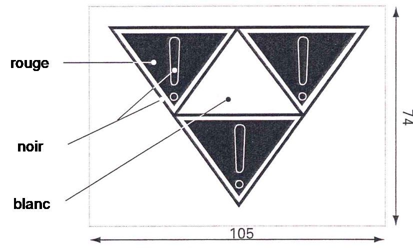
5.4 Sign for wagons not to be loose-shunted
Red
Black
White
Position: On the left of each solebar, or on parts covering the solebar or on special boards
fitted at the same height as the solebars.
Meaning: Special care should be taken when marshalling trains to avoid damaging the
wagon. Wagon must not be loose-shunted must not be loose-shunted and must
be protected against buffing by other rolling stock without taking special
precautions.
N.B.: This marking is compulsory on wagons with special fittings (electronic equipment,
refrigerator units, etc.) for which normal buffing impacts are not authorised as
they are liable to damage the equipment. These wagons may not carry the RIV
sign but can be covered by bilateral agreements.
Version: 1-jan-2021 51GENERAL CONTRACT OF USE FOR WAGONS APPENDIX 11
5.5 Sign for wagons that must not be fly- or gravity-shunted
Red
Black
White
Position: On the left of each solebar, or on parts covering the solebar or on special boards
fitted at the same height as the solebars.
Meaning: Wagon
must not be fly- or gravity-shunted,
must be marshalled by a motive power unit,
must not be loose-shunted and must be protected against buffing by other
rolling stock.
N.B.: Point 5.3.4.1 of the RID states that in place of the shunting label (shown in model
15) the wagon may instead carry permanent shunting signs (wagon markings)
providing they conform precisely to the prescribed example.
5.6 Sign for fly and hump shunting not permitted for containers or loaded pocket
wagons
NB: Fly or hump shunting and buffing is not permitted when the wagon is loaded.
Shunting may be performed without restriction when the wagon is empty.
Version: 1-jan-2021 52GENERAL CONTRACT OF USE FOR WAGONS APPENDIX 11
5.6 Marking for wagons fitted with anti-crash components
Yellow Black
Position: On the headstocks, between the buffers.
Appearence: Paint: black diagonal warning stripes painted on a yellow background.
Meaning: Wagon fitted with anti-crash components. The Berne rectangle clearances may
be encroached. Follow shunting instructions.
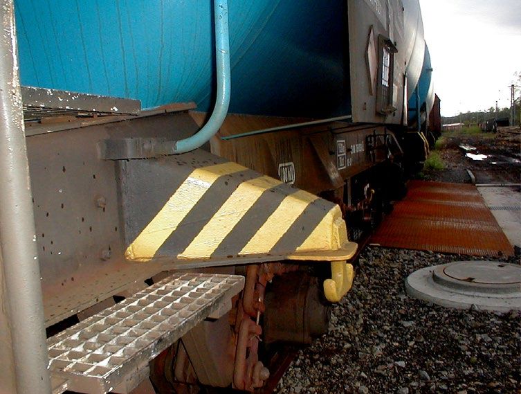
5.7 Marking for wagons fitted with long-stroke shock absorbers (schock
absorber fitting)
Black and yellow striped surface to
be left clear
Position: Black diagonal warning stripes painted on a yellow background covering the
danger areas for wagons fitted with shock absorbers.
Meaning: In the event of impact, the wagon ends become displaced in relation to the
underframe. Distances and clearances are reduced as a result. Particular care
must therefore be taken during shunting operations.
Version: 1-jan-2021 53GENERAL CONTRACT OF USE FOR WAGONS APPENDIX 11
5.8 Marking for wagons fitted with projecting tow hooks
Position: Tow hooks and their fenders projecting more than 150 mm, and any supports and
brackets, should be colour-marked as follows:
- Tow hooks and fenders: in yellow.
Colour-marking of tow hook supports and brackets:
- Projecting up to 250 mm: in yellow,
- Projecting more than 250 mm: black diagonal stripes on yellow background.
Meaning: Marking serving as a warning against the risk of injury.
5.9 Sign for permanently-coupled wagon units
Colour contrasting with
that of the vehicle
Position: On each headstock, next to the right-hand buffer.
Meaning: Not to be uncoupled in service. This sign is only used on wagons made up of
several units that are permanently coupled together.
Version: 1-jan-2021 54GENERAL CONTRACT OF USE FOR WAGONS APPENDIX 11
5.10 Sign for bogie wagons only able to negotiate curves with a radius greater
than 35 m
Position: On the left of each solebar, or on parts covering the solebar or on special boards
fitted at the same height as the solebars.
Meaning: Indicates the minimum curve radius that the wagon can negotiate.
N.B.: On wagons with special fittings, for example low-loader wagons, this indication
refers to the central position of the lateral sliding device and/or the maximum
distance between bogie centres.
5.11 Signs indicating wagons fitted with a train line
For 3000 V For 3000 V and 50 Hz For 1500 V For 1500 and 50 Hz For 1000 V
Position: On the lower part of the corner posts, on both outward-facing surfaces. For
wagons without corner posts, it is recommended that the required markings be
affixed to metal panels.
Appearance: Light yellow rectangle approx. 200 mm high, the same width as the corner post
and with the top corner cut off at an angle of approx. 45° inclined downwards
towards the centre of the wagon. Black horizontal stripes approx. 15 mm high are
painted on the yellow rectangle at intervals of 15 mm.
Meaning: Wagon is fitted with a train line. One black stripe indicates a 1000 V DC cable,
two stripes a 1500 V cable and three stripes a 3000 V cable. Approval for running
on 50 Hz AC electrified networks is indicated by the number "50".
Version: 1-jan-2021 55GENERAL CONTRACT OF USE FOR WAGONS APPENDIX 11
5.12 Sign for wagons fitted with the automatic coupler
Sign according to
OSJD* standard
Position: At each end of the wagon sides or solebar and on each end wall.
Meaning: Wagon fitted with automatic couplers.
N.B.: On wagons fitted with the automatic coupler, the Berne rectangle clearances may
be partially encroached.
*OSJD: Organisation for Collaboration between Railways, based in Warsaw.
5.13 Sign for derailment detectors
Position: On both sides of the wagon, when the derailment detector is visible. The picture
on the sign has a dotted outline when the detector is not visible.
Meaning: Wagon derailment detectors are devices used to detect implausibly high vertical
accelerations on the vehicle. A derailment is assumed to have taken place and an
emergency brake application is triggered or an alarm sounded. The system
cannot prevent a derailment itself from occurring.
Version: 1-jan-2021 56GENERAL CONTRACT OF USE FOR WAGONS APPENDIX 11
5.14 Sign for strengthened screw coupling
Key 1 Black
2 Yellow
Position: At each extremity of the side faces of the wagon or on frame girder. This marking
must be chosen according to the reserved space for that purpose.
Meaning: Wagon with strengthened screw coupling – X t is related to coupling resistance,
Y t to coupling hook. A strengthened screw coupling is described in
EN 15566:2009, paragraph 4.1, table 1. System’s recognition is over 1 MN.
Version: 1-jan-2021 57GENERAL CONTRACT OF USE FOR WAGONS APPENDIX 11
– reserved –
Version: 1-jan-2021 58GENERAL CONTRACT OF USE FOR WAGONS APPENDIX 11
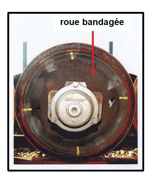
6.1 Sign for wheels able to withstand high thermal stresses
Position: On the axle-box cover.
Meaning: The axles in question have wheels that are able to withstand high thermal
loading, in accordance with UIC Leaflets 510-2 and 510-5, Appendix H
6.2 Marking of tyred wheels
tyred wheel
Position: Four coloured stripes, at 90° intervals, on the outer surface of the wheel tyre and
rim.
Meaning: Control mark to check the position of the tyre in relation to the wheel rim.
Version: 1-jan-2021 59GENERAL CONTRACT OF USE FOR WAGONS APPENDIX 11
6.4 Sign for ventilation pipes
White Black
background
Black border
Position: On tanks, next to the pipes in question.
Meaning: The ventilation pipes marked with this symbol must not be sealed off.
6.5 Sign for tank wagon tests, coding of tanks and special regulations
Figure 1 Figure 2 (example)
TE 5
Position: On each side of each tank, on the right.
Meaning Indication of the next tank test (end of month) for the carriage of dangerous goods
figure 1: in accordance with the RID. The marking specifies (1) the month (2) the year and
if necessary the letter “L” as per RID 6.8.2.4.3.; 3) that the date of the next tank
test is extended by 3 months.
Meaning Example of an alphanumerical code for all the special regulations* applicable:
figure 2: here, the wagon is fitted with a highly flammable insulating material.
*N.B.: The tank code should also be marked near the date of the tank test, in characters
at least 90 mm high. The alphanumerical code for all applicable special
regulations under the RID should also feature below the tank code or right beside
it, in characters 50 mm high. This marking must be made by 1/1/2011 at the
latest.
Version: 1-jan-2021 60You can also read