Performant TCP for Low-Power Wireless Networks
←
→
Page content transcription
If your browser does not render page correctly, please read the page content below
Performant TCP for Low-Power Wireless Networks
                                                             Sam Kumar, Michael P Andersen, Hyung-Sin Kim, and David E. Culler
                                                                             University of California, Berkeley

                                                                  Abstract                                     is that IP holds merit, but TCP is ill-suited to LLNs. This view
                                                                                                               is represented by concerns about TCP, such as:
                                         Low-power and lossy networks (LLNs) enable diverse appli-
                                         cations integrating many resource-constrained embedded de-            • “TCP is not light weight ... and may not be suitable for
                                         vices, often requiring interconnectivity with existing TCP/IP           implementation in low-cost sensor nodes with limited pro-
                                         networks as part of the Internet of Things. But TCP has re-             cessing, memory and energy resources.” [110] (Similar ar-
                                                                                                                 gument in [42], [75].)
arXiv:1811.02721v3 [cs.NI] 28 Feb 2020

                                         ceived little attention in LLNs due to concerns about its over-
                                         head and performance, leading to LLN-specific protocols that          • That “TCP is a connection-oriented protocol” is a poor
                                         require specialized gateways for interoperability. We present           match for WSNs, “where actual data might be only in the
                                         a systematic study of a well-designed TCP stack in IEEE                 order of a few bytes.” [114] (Similar argument in [110].)
                                         802.15.4-based LLNs, based on the TCP protocol logic in               • “TCP uses a single packet drop to infer that the network
                                         FreeBSD. Through careful implementation and extensive ex-               is congested.” This “can result in extremely poor trans-
                                         periments, we show that modern low-power sensor platforms               port performance because wireless links tend to exhibit
                                         are capable of running full-scale TCP and that TCP, counter             relatively high packet loss rates.” [109] (Similar argument
                                         to common belief, performs well despite the lossy nature of             in [43], [44], [75].)
                                         LLNs. By carefully studying the interaction between the trans-        Such viewpoints have led to a plethora of WSN-specialized
                                         port and link layers, we identify subtle but important modi-          protocols and systems [110, 117, 132] for reliable data trans-
                                         fications to both, achieving TCP goodput within 25% of an             port, such as PSFQ [130], STCP [75], RCRT [109], Flush [88],
                                         upper bound (5–40x higher than prior results) and low-power           RMST [125], Wisden [138], CRRT [10], and CoAP [31], and
                                         operation commensurate to CoAP in a practical LLN applica-            for unreliable data transport, like CODA [131], ESRT [118],
                                         tion scenario. This suggests that a TCP-based transport layer,        Fusion [71], CentRoute [126], Surge [94], and RBC [142].
                                         seamlessly interoperable with existing TCP/IP networks, is               As LLNs become part of the emerging Internet of Things
                                         viable and performant in LLNs.                                        (IoT), it behooves us to re-examine the transport question,
                                                                                                               with attention to how the landscape has shifted: (1) As part
                                         1   Introduction                                                      of IoT, LLNs must be interoperable with traditional TCP/IP
                                         Research on wireless networks of low-power, resource con-             networks; to this end, using TCP in LLNs simplifies IoT
                                         strained, embedded devices—low-power and lossy networks               gateway design. (2) Popular IoT application protocols, like
                                         (LLNs) in IETF terms [128]—blossomed in the late 1990s.               MQTT [39] and ZeroMQ [8], assume that TCP is used at the
                                         To obtain freedom to tackle the unique challenges of LLNs,            transport layer. (3) Some IoT application scenarios demand
                                         researchers initially departed from the established conven-           high link utilization and reliability on low-bandwidth lossy
                                         tions of the Internet architecture [50, 68]. As the field ma-         links. Embedded hardware has also evolved substantially,
                                         tured, however, researchers found ways to address these chal-         prompting us to revisit TCP’s overhead. In this context, this
                                         lenges within the Internet architecture [70]. Since then, it          paper seeks to determine: Do the “common wisdom” con-
                                         has become commonplace to use IPv6 in LLNs via the                    cerns about TCP hold in a modern IEEE 802.15.4-based
                                         6LoWPAN [105] adaptation layer. IPv6-based routing pro-               LLN? Is TCP (still) unsuitable for use in LLNs?
                                         tocols, like RPL [33], and application-layer transports over             To answer this question, we leverage the fully-featured TCP
                                         UDP, like CoAP [35], have become standards in LLNs. Most              implementation in the FreeBSD Operating System (rather
                                         wireless sensor network (WSN) operating systems, such as              than a limited locally-developed implementation) and refactor
                                         TinyOS [95], RIOT [24], and Contiki [45], ship with IP imple-         it to work with the Berkeley Low-Power IP Stack (BLIP),
                                         mentations enabled and configured. Major industry vendors             Generic Network Stack (GNRC), and OpenThread network
                                         offer branded and supported 6LoWPAN stacks (e.g., TI Sim-             stack, on two modern LLN platforms (§5). Naïvely running
                                         pleLink, Atmel SmartConnect). A consortium, Thread [64],              TCP in an LLN indeed results in poor performance. However,
                                         has formed around 6LoWPAN-based interoperability.                     upon close examination, we discover that this is not caused by
                                            Despite these developments, transport in LLNs has re-              the expected reasons, such as those listed above. The actual
                                         mained ad-hoc and TCP has received little serious consid-             reasons for poor TCP performance include (1) small link-
                                         eration. Many embedded IP stacks (e.g., OpenThread [106])             layer frames that increase TCP header overhead, (2) hidden
                                         do not even support TCP, and those that do implement only a           terminal effects over multiple wireless hops, and (3) poor
                                         subset of its features (Appendix B). The conventional wisdom          interaction between TCP and a duty-cycled link. Through

                                                                                                           1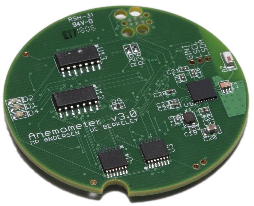
Challenge      Technique         Observed Improvement                  4. We demonstrate that, once these issues are resolved, TCP
 Resource Zero-Copy Send Send Buffer: 50% less mem.                        performs comparably to LoWPAN-specialized protocols.
Constraints In-Place Reass. Recv Buffer: 38% less mem.                  Table 1 lists our techniques to run TCP in an LLN. Although
Link-Layer     Large MSS        TCP Goodput: 4–5x higher                prior LLN work has already used various forms of link-layer
 Properties Link Retry Delay TCP Seg. Loss: 6% → 1%                     delays [136] and adaptive duty-cycling [140], our work shows,
                                                                        where applicable, how to adapt these techniques to work well
  Energy      Adaptive DC HTTP Latency: ≈ 2x lower
                                                                        with TCP, and demonstrates that they can address the chal-
Constraints L2 Queue Mgmt. TCP Radio DC: 3% → 2%
                                                                        lenges of LLNs within a TCP-based transport architecture.
Table 1: Impact of techniques to run full-scale TCP in LLNs
                                                                        2     Background and Related Work
a systematic study of TCP in LLNs, we develop techniques                Since the introduction of TCP, a vast literature has emerged,
to resolve these issues (Table 1), uncover why the generally            focusing on improving it as the Internet evolved. Some rep-
assumed problems do not apply to TCP in LLNs, and show                  resentative areas include congestion control [9, 51, 62, 76],
that TCP perfoms well in LLNs once these issues are resolved:           performance on wireless links [15, 27], performance in high-
   We find that full-scale TCP fits well within the CPU and             bandwidth environments [11, 30, 53, 65, 78], mobility [124],
memory constraints of modern LLN platforms (§5, §6).                    and multipath operation [115]. Below, we discuss TCP in the
Owing to the low bandwidth of a low-power wireless link, a              context of LLNs and embedded devices.
small window size (≈ 2 KiB) is sufficient to fill the bandwidth-        2.1    Low-Power and Lossy Networks (LLNs)
delay product and achieve good TCP performance. This trans-             Although the term LLN can be applied to a variety of tech-
lates into small send/receive buffers that fit comfortably within       nologies, including LoRa and Bluetooth Low Energy, we re-
the memory of modern WSN hardware. Furthermore, we                      strict our attention in this paper to embedded networks using
propose using an atypical Maximum Segment Size (MSS)                    IEEE 802.15.4. Such networks are called LoWPANs [93]—
to manage header overhead and packet fragmentation. As                  Low-Power Wireless Personal Area Networks—in contrast
a result, full-scale TCP operates well in LLNs, with 5–40               to WANs, LANs (802.3), and WLANs (802.11). Outside of
times higher throughput than existing (relatively simplis-              LoWPANs, TCP has been successfully adapted to a variety of
tic) embedded TCP stacks (§6).                                          networks, including serial [77], Wi-Fi [27], cellular [25, 100],
   Hidden terminals are a serious problem when running TCP              and satellite [15,25] links. While an 802.15.4 radio can in prin-
over multiple wireless hops. We propose adding a delay d                ciple be added as a NIC to any device, we consider only em-
between link-layer retransmissions, and demonstrate that it             bedded devices where it is the primary means of communica-
effectively reduces hidden-terminal-induced packet loss for             tion, running operating systems like TinyOS [68], RIOT [24],
TCP. We find that, because a small window size is sufficient            Contiki [45], or FreeRTOS. These devices are currently built
for good performance in LLNs, TCP is quite resilient to spu-            around microcontrollers with Cortex-M CPUs, which lack
rious packet losses, as the congestion window can recover               MMUs. Below, we explain how LoWPANs are different from
to a full window quickly after loss (§7).                               other networks where TCP has been successfully adapted.
   To run TCP in a low-power context, we adaptively duty-               Resource Constraints. When TCP was initially adopted
cycle the radio to avoid poor interactions with TCP’s self-             by ARPANET in the early 1980s, contemporary Internet
clocking behavior. We also propose careful link-layer queue             citizens—typically minicomputers and high-end workstations,
management to make TCP more robust to interference. We                  but not yet personal computers—usually had at least 1 MiB of
demonstrate that TCP can operate at low power, compara-                 RAM. 1 MiB is tiny by today’s standards, yet the LLN-class
ble to alternatives tailored specifically for WSNs, and that            devices we consider in this work have 1-2 orders of magnitude
TCP brings value for real IoT sensor applications (§8).                 less RAM than even the earliest computers connected with
   We conclude that TCP is entirely capable of running on               TCP/IP. Due to energy constraints, particularly SRAM leak-
IEEE 802.15.4 networks and low-cost embedded devices in                 age, RAM size in low-power MCUs does not follow Moore’s
LLN application scenarios (§9). Since our improvements to               Law. For example, comparing Hamilton [83], which we use
TCP and the link layer maintain seamless interoperability with          in this work, to TelosB [113], an LLN platform from 2004,
other TCP/IP networks, we believe that a TCP-based transport            shows only a 3.2x increase in RAM size over 16 years. This
architecture for LLNs could yield considerable benefit.                 has caused LLN-class embedded devices to have a different
   In summary, this paper’s contributions are:                          balance of resources than conventional systems, a trend that is
1. We implement a full-scale TCP stack for low-power em-                likely to continue well into the future. For example, whereas
    bedded devices and reduce its resource usage.                       conventional computers have historically had roughly 1 MiB
2. We identify the actual issues causing poor TCP perfor-               of RAM for every MIPS of CPU, as captured by the 3M rule,
    mance and develop techniques to address them.                       Hamilton has ≈ 50 DMIPS of CPU but only 32 KiB of RAM.
3. We explain why the expected insurmountable reasons for               Link-Layer Properties. IEEE 802.15.4 is a low-bandwidth,
    poor TCP performance actually do not apply.                         wireless link with an MTU of only 104 bytes. The research

                                                                    2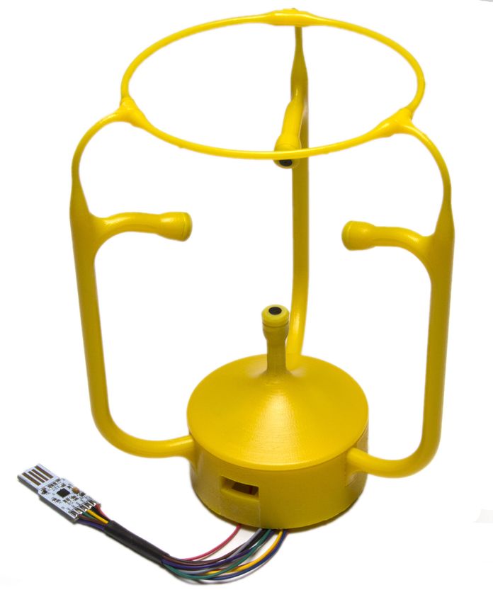
community has explored using TCP with links that are sepa-              and resource constraints, from S-MAC [139], B-MAC [112],
rately low-bandwidth, wireless [27], or low-MTU [77], but               X-MAC [34], and A-MAC [49], to Trickle [96] and CTP [59].
addressing these issues together raises new challenges. For ex-         Researchers have viewed TCP as unsuitable, however, ques-
ample, RTS-CTS, used in WLANs to avoid hidden terminals,                tioning end-to-end recovery, loss-triggered congestion con-
has high overhead in LoWPANs [71, 136] due to the small                 trol, and bi-directional data flow in LLNs [44]. Furthermore,
MTU—control frames are comparable in size to data frames.               WSNs of this era typically did not even use IP; instead, each
Thus, LoWPAN researchers have moved away from RTS-                      WSN was designed specifically to support a particular appli-
CTS, instead carefully designing application traffic patterns           cation [89, 102, 138]. Those that require global connectivity
to avoid hidden terminals [71, 88, 112]. Unlike Wi-Fi/LTE,              rely on application-specific “base stations” or “gateways” con-
LoWPANs do not use physical-layer techniques like adaptive              nected to a TCP/IP network, treating the LLN like a peripheral
modulation/coding or multi-antenna beamforming. Thus, they              interconnect (e.g., USB, bluetooth) rather than a network in its
are directly impacted by link quality degradation due to vary-          own right. This is because the prevailing sentiment at the time
ing environmental conditions [112, 127]. Additionally, IEEE             was that LLNs are too different from other types of networks
802.15.4 coexists with Wi-Fi in the 2.4 GHz frequency band,             and have to operate in too extreme conditions for the layered
making Wi-Fi interference particularly relevant in indoor set-          Internet architecture to be appropriate [50].
tings [99]. As LoWPANs are embedded networks, there is no                  In 2007, the 6LoWPAN adaptation layer [105] was intro-
human in the loop to react to and repair bad link quality.              duced, enabling IPv6 over IEEE 802.15.4. IPv6 has since been
Energy Constraints. Embedded nodes—the “hosts” of an                    adopted in LLNs, bringing forth IoT [70]. uIP has been ported
LLN—are subject to strict power constraints. Low-power ra-              to LLNs [48], and IPv6 routing protocols, like RPL [33], and
dios consume almost as much energy listening for a packet as            UDP-based application-layer transports, like CoAP [35], have
they do when actually sending or receiving [20, 83]. There-             emerged in LLNs. Representative operating systems, like
fore, it is customary to duty-cycle the radio, keeping it in a          TinyOS and Contiki, implement UDP/RPL/IPv6/6LoWPAN
low-power sleep state, in which it cannot send or receive data,         network stacks with IEEE 802.15.4-compatible MMC proto-
most of the time [70,112,139]. The radio is only occasionally           cols for 16-bit platforms like TelosB [113].
turned on to send/receive packets or determine if reception                TCP, however, is not widely adopted in LLNs. The few
is likely. This requires Media Management Control (MMC)                 LLN studies that use TCP [47,60,67,70,72,86,144] generally
protocols [70, 112, 139] at the link layer to ensure that frames        use a simplified TCP stack (Appendix B), such as uIP.
destined for a node are delivered to it only when its radio is on          In summary, despite the acceptance of IPv6, LLNs remain
and listening. Similarly, the CPU also consumes a significant           highly tailored at the transport layer to the application at hand.
amount of energy [83], and must be kept idle most of the time.          They typically use application-specific protocols on top of
                                                                        UDP; of such protocols, CoAP [31] has the widest adoption.
   Over the past 20 years, LLN researchers have addressed
                                                                        In this context, this paper explores whether adopting TCP—
these challenges, but only in the context of special-purpose
                                                                        and more broadly, the ecosystem of IP-based protocols, rather
networks highly tailored to the particular application task at
                                                                        than IP alone—might bring value to LLNs moving forward.
hand. The remaining open question is how to do so with a
general-purpose reliable transport protocol like TCP.                   3    Motivation: The Case for TCP in LLNs
                                                                        As explained in §2, LLN design has historically been highly
2.2    TCP/IP for Embedded LLN-Class Devices                            tailored to the specific application task at hand, for maxi-
In the late 1990s and early 2000s, developers attempted to              mum efficiency. For example, PSFQ broadcasts data from a
bring TCP/IP to embedded and resource-constrained systems               single source node to all others, RMST supports “directed
to connect them to the Internet, usually over serial or Ethernet.       diffusion” [73], and CoAP is tied to REST semantics. But
Such systems [32, 80] were often designed with a specific               embedded networks are not just isolated devices (e.g., periph-
application—often, a web server—in mind. These TCP/IP                   eral interconnects like USB or bluetooth)—they are now true
stacks were tailored to the specific applications at hand and           Internet citizens, and should be designed as such.
were not suitable for general use. uIP (“micro IP”) [42], in-              In particular, the recent megatrend of IoT requires LLNs to
troduced in 2002, was a standalone general TCP/IP stack                 have a greater degree of interoperability with regular TCP/IP
optimized for 8-bit microcontrollers and serial or Ethernet             networks. Yet, LLN-specific protocols lack a clear separa-
links. To minimize resource consumption to run on such plat-            tion between the transport and application layers, requiring
forms, uIP omits standard features of TCP; for example, it              application-layer gateways to communicate with TCP/IP-
allows only a single outstanding (unACKed) TCP segment                  based services. This has encouraged IoT applications to de-
per connection, rather than a sliding window of in-flight data.         velop as vertically-integrated silos, where devices cooperate
   Since the introduction of uIP, embedded networks have                only within an individual application or a particular manufac-
changed substantially. With wireless sensor networks and                turer’s ecosystem, with little to no interoperability between
IEEE 802.15.4, various low-power networking protocols have              applications or with the general TCP/IP-based Internet. This
been developed to overcome lossy links with strict energy               phenomenon, sometimes called the “CompuServe of Things,”

                                                                    3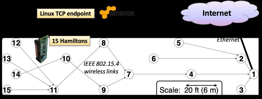
is a serious obstacle to the IoT vision [57,97,104,133,141]. In TelosB Hamilton Firestorm Raspberry Pi
contrast, other networks are seamlessly interoperable with the CPU MSP430 Cortex-M0+ Cortex-M4 Cortex-A53
rest of the Internet. Accessing a new web application from a RAM 10 KiB 32 KiB 64 KiB 256 MB
laptop does not require any new functionality at the Wi-Fi ac- ROM 48 KiB 256 KiB 512 KiB SD Card
cess point, but running a new application in a gateway-based Table 2: Comparison of the platforms we used (Hamilton and
LLN does require additional application-specific functionality Firestorm) to TelosB and Raspberry Pi
to be installed at the gateway.
In this context, TCP-enabled LLN devices would be first- LTE/WLANs [55, 135]. Unfortunately, multihop LLNs have
class citizens of the Internet, natively interoperable with the not yet reached the level of maturity to support a variety of
rest of the Internet via TCP/IP. They could use IoT protocols commercial offerings; only CoAP has an appreciable level of
that assume a TCP-based transport layer (e.g., MQTT [39]) commercial adoption. Other protocols are research proposals
and security tools for TCP/IP networks (e.g., stateful fire- that often (1) are implemented for now-outdated operating
walls), without an application-layer gateway. In addition, systems and hardware or exist only in simulation [10, 75, 88],
while traditional LLN applications like environment mon- (2) target a very specific application paradigm [125, 130, 138],
itoring can be supported by unreliable UDP, certain applica- and/or (3) do not use IP [75, 88, 109, 130]. We choose CoAP
tions do require high throughput and reliable delivery (e.g., and CoCoA because they are not subject to these constraints.
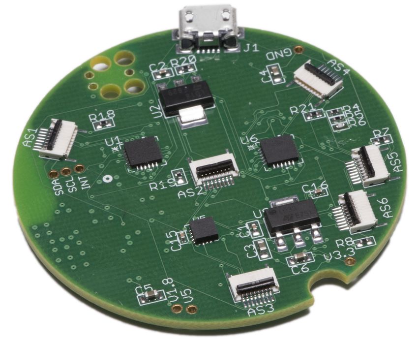
anemometry (Appendix D), vibration monitoring [81]). TCP, Layers 1 to 3. Because it is burdensome to place a border
if it performs well in LLNs, could benefit these applications. router with LAN connectivity within wireless range of every
Adopting TCP in LLNs may also open an interesting re- low-power host (e.g., sensor node), it is common to transmit
search agenda for IoT. TCP is the default transport protocol data (e.g., readings) over multiple wireless LLN hops. Al-
outside of LLNs, and history has shown that, to justify other though each sensor must be battery-powered, it is reasonable
transport protocols, application characteristics must offer sub- to have a wall-powered LLN router node within transmission
stantial opportunity for optimization (e.g., [55, 134, 135]). If range of it.1 This motivates Thread2 [64, 87], a recently devel-
TCP becomes a viable option in LLNs, it would raise the oped protocol standard that constructs a multihop LLN over
bar for application-specific LLN protocols, resulting in some IEEE 802.15.4 links with wall-powered, always-on router
potentially interesting alternatives. nodes and battery-powered, duty-cycled leaf nodes. We use
Although adopting TCP in LLNs could yield significant OpenThread [106], an open-source implementation of Thread.
benefit and an interesting agenda, its feasibility and perfor- Thread decouples routing from energy efficiency, providing
mance remain in question. This motivates our study. a full-mesh topology among routers, frequent route updates,
4 Empirical Methodology and asymmetric bidirectional routing for reliability. Each leaf
This section presents our methodology, carefully chosen to node duty cycles its radio, and simply chooses a core router
ground our study of full-scale TCP in LLNs. with good link quality, called its parent, as its next hop to all
other nodes. The duty cycling uses listen-after-send [120]. A
4.1 Network Stack leaf node’s parent stores downstream packets destined for that
Transport layer. That only a few full-scale TCP stacks exist, leaf node, until the leaf node sends it a data request message.
with a body of literature covering decades of refining, demon- A leaf node, therefore, can keep its radio powered off most
strates that developing a feature-complete implementation of of the time; infrequently, it sends a data request message to
TCP is complex and error-prone [111]. Using a well-tested its parent, and turns on its radio for a short interval afterward
TCP implementation would ensure that results from our mea- to listen for downstream packets queued at its parent. Leaf
surement study are due to the TCP protocol, not an artifact nodes may send upstream traffic at any time. Each node uses
of the TCP implementation we used. Thus, we leverage the CSMA-CA for medium access.
TCP implementation in FreeBSD 10.3 [56] to ground our
4.2 Embedded Hardware
study. We ported it to run in embedded operating systems and
We use two embedded hardware platforms: Hamilton [83]
resource-constrained embedded devices (§4.2).
and Firestorm [18]. Hamilton uses a SAMR21 SoC with a 48
To verify the effectiveness of full-scale TCP in LLNs, we
MHz Cortex-M0+, 256 KiB of ROM, and 32 KiB of RAM.
compare with CoAP [123], CoCoA [29], and unreliable UDP.
Firestorm uses a SAM4L 48 MHz Cortex-M4 with 512 KiB
CoAP is a standard LLN protocol that provides reliability
of ROM and 64 KiB of RAM. While these platforms are more
on top of UDP. It is the most promising LLN alternative to
powerful than the TelosB [113], an older LLN platform widely
TCP, gaining momentum in both academia [29, 38, 90, 119,
121, 129] and industry [3, 79], with adoption by Cisco [5, 41], 1 The assumption of powered “core routers” is reasonable for most IoT use
Nest/Google [4], and Arm [1, 2]. CoCoA [29] is a recent cases, which are typically indoors. Recent IoT protocols, such as Thread [64]
and BLEmesh [63], take advantage of powered core routers.
proposal that augments CoAP with RTT estimation. 2 Thread has a large amount of industry support with a consortium already
It is attractive to compare TCP to a variety of commer- consisting of over 100 members [6], and is used in real IoT products sold by
cial systems, as has been done by a number of studies in Nest/Google [7]. Given this trend, using Thread makes our work timely.
4Protocol Socket Layer posix_sockets
ROM 19972 B 6216 B 5468 B
RAM (Active) 364 B 88 B 48 B
RAM (Passive) 12 B 88 B 48 B
Table 3: Memory usage of TCPlp on RIOT OS. We also
include RIOT’s posix_sockets module, used by TCPlp to
provide a Unix-like interface.
Figure 1: Snapshot of uplink routes in OpenThread topology
mant operation on sensor platforms was a nontrivial effort.
at transmission power of -8 dBm (5 hops). Node 1 is the
We had to modify the FreeBSD implementation according to
border router with Internet connectivity.
the concurrency model of each embedded network stack and
used in past studies, they are heavily resource-constrained the timer abstractions provided by each embedded operating
compared to a Raspberry Pi (Table 2). Both platforms use the system (Appendix A). Our other modifications to FreeBSD,
AT86RF233 radio, which supports IEEE 802.15.4. We use its aimed at reducing memory footprint, are described below.
standard data rate, 250 kb/s. We use Hamilton/OpenThread 5.1 Connection State for TCPlp
in our experiments; for comparison, we provide some results As discussed in Appendix B, TCPlp includes features from
from Firestorm and other network stacks in Appendix A. FreeBSD that improve standard communication, like a slid-
Handling automatic radio features. The AT86RF233 radio ing window, New Reno congestion control, zero-window
has built-in hardware support for link-layer retransmissions probes, delayed ACKs, selective ACKs, TCP timestamps, and
and CSMA-CA. However, it automatically enters low-power header prediction. TCPlp, however, omits some features in
mode during CSMA backoff, during which it does not listen FreeBSD’s TCP/IP stack. We omit dynamic window scaling,
for incoming frames [20]. This behavior, which we call deaf as buffers large enough to necessitate it (≥ 64 KiB) would
listening, interacts poorly with TCP when radios are always not fit in memory. We omit the urgent pointer, as it not rec-
on, because TCP requires bidirectional flow of packets—data ommended for use [61] and would only complicate buffering.
in one direction and ACKs in the other. This may initially Certain security features, such as host cache, TCP signatures,
seem concerning, as deaf listening is an important power- SYN cache, and SYN cookies are outside the scope of this
saving feature. Fortunately, this problem disappears when work. We do, however, retain challenge ACKs [116].
using OpenThread’s listen-after-send duty-cycling protocol, We use separate structures for active sockets used to send
as leaf nodes never transmit data when listening for down- and receive bytes, and passive sockets used to listen for in-
stream packets. For experiments with always-on radios, we coming connections, as passive sockets require less memory.
do not use the radio’s capability for hardware CSMA and link Table 3 depicts the memory footprint of TCPlp on RIOT
retries; instead, we perform these operations in software. OS. The memory required for the protocol and application
Multihop Testbed. We construct an indoor LLN testbed, de- state of an active TCP socket fits in a few hundred bytes, less
picted in Figure 1, with 15 Hamiltons where node 1 is con- than 1% of the available RAM on the Cortex-M4 (Firestorm)
figured as the border router. OpenThread forms a 3-to-5-hop and 2% of that on the Cortex-M0+ (Hamilton). Although TC-
topology at transmission power of -8 dBm. Embedded TCP Plp includes heavyweight features not traditionally included
endpoints (Hamiltons) communicate with a Linux TCP end- in embedded TCP stacks, it fits well within available memory.
point (server on Amazon EC2) via the border router. During 5.2 Memory-Efficient Data Buffering
working hours, interference is present in the channel, due to Existing embedded TCP stacks, such as uIP and BLIP, allow
people in the space using Wi-Fi and Bluetooth devices in the only one TCP packet in the air, eschewing careful imple-
2.4 GHz frequency band. At night, when there are few/no mentation of send and receive buffers [86]. These buffers,
people in the space, there is much less interference. however, are key to supporting TCP’s sliding window func-
5 Implementation of TCPlp tionality. We observe in §6.2 that TCPlp performs well with
We seek to answer the following two questions: (1) Does only 2-3 KiB send and receive buffers, which comfortably fit
full-scale TCP fit within the limited memory of modern LLN in memory even when naïvely pre-allocated at compile time.
platforms? (2) How can we integrate a TCP implementation Given that buffers dominate TCPlp’s memory usage, however,
from a traditional OS into an embedded OS? To this end, we discuss techniques to optimize their memory usage.
we develop a TCP stack for LLNs based on the TCP imple- 5.2.1 Send Buffer: Zero-Copy
mentation in FreeBSD 10.3, called TCPlp [91], on multiple Zero-copy techniques [28, 40, 82, 98, 101] were devised for
embedded operating systems, RIOT OS [24] and TinyOS [95]. situations where the time for the CPU to copy memory is
We use TCPlp in our measurement study in future sections. a significant bottleneck. Our situation is very different; the
Although we carefully preserved the protocol logic in the radio, not the CPU, is the bottleneck, owing to the low band-
FreeBSD TCP implementation, achieving correct and perfor- width of IEEE 802.15.4. By using a zero-copy send buffer,
5Fast Ethernet Wi-Fi Ethernet 802.15.4
Capacity 100 Mb/s 54 Mb/s 10 Mb/s 250 kb/s
(a) Naïve receive buffer. Note that size of advertised window + MTU 1500 B 1500 B 1500 B 104–116 B
size of buffered data = size of receive buffer.
Tx Time 0.12 ms 0.22 ms 1.2 ms 4.1 ms
Table 4: Comparison of TCP/IP links
(b) Receive buffer with in-place reassembly queue. In-sequence data Header 802.15.4 6LoWPAN IPv6 TCP Total
(yellow) is kept in a circular buffer, and out-of-order segments (red) 1st Frame 11–23 B 5B 2–28 B 20–44 B 38–107 B
are written in the space past the received data. nth Frame 11–23 B 5–12 B 0B 0B 16–35 B
Figure 2: Naïve and final TCP receive buffers Table 5: Header overhead with 6LoWPAN fragmentation
however, we can avoid allocating memory to intermediate nus the size of the TCP/IP headers. IEEE 802.15.4 frames,
buffers that would otherwise be needed to copy data, thereby however, are an order of magnitude smaller than frames in
reducing the network stack’s total memory usage. traditional networks (Table 4). The TCP/IP headers consume
In TinyOS, for example, the BLIP network stack supports more than half of the frame’s available MTU. As a result, TCP
vectored I/O; an outgoing packet passed to the IPv6 layer is performs poorly, incurring more than 50% header overhead.
specified as an iovec. Instead of allocating memory in the
Earlier approaches to running TCP over low-MTU links
packet heap for each outgoing packet, TCPlp simply creates
(e.g., low-speed serial links) have used TCP/IP header com-
iovecs that point to existing data in the send buffer. This
pression based on per-flow state [77] to reduce header over-
decreases the required size of the packet heap.
head. In contrast, the 6LoWPAN adaptation layer [105], de-
Unfortunately, zero-copy optimizations were not possible
signed for LLNs, supports only flow-independent compression
for the OpenThread implementation, because OpenThread
of the IPv6 header using shared link-layer state, a clear depar-
does not support vectored I/O for sending packets. The result
ture from per-flow techniques. A key reason for this is that
is that the TCPlp implementation requires a few kilobytes of
the compressor and decompressor in an LLN (host and border
additional memory for the send buffer on this platform.
router) are separated by several IP hops,3 making it desirable
5.2.2 Receive Buffer: In-Place Reassembly Queue for intermediate nodes to be able to determine a packet’s IP
Not all zero-copy optimizations are useful in the embedded header without per-flow context (see §10 of [105]).
setting. In FreeBSD, received packets are passed to the TCP That said, compressing TCP headers separately from IP
implementation as mbufs [137]. The receive buffer and re- addresses using per-flow state is a promising approach to fur-
assembly buffer are mbuf chains, so data need not be copied ther amortize header overhead. There is preliminary work in
out of mbufs to add them to either buffer or recover from this direction [22, 23], but it is based on uIP, which has one
out-of-order delivery. Furthermore, buffer sizes are chosen in-flight segment, and does not fully specify how to resynchro-
dynamically [122], and are merely a limit on their actual size. nize compression state after packet loss with a multi-segment
In our memory-constrained setting, such a design is danger- window. It is also not officially standardized by the IETF.
ous because its memory usage is nondeterministic; there is Therefore, this paper takes an approach orthogonal to
additional memory overhead, due to headers, if the data are header compression. We instead choose an MSS larger than
delivered in many small packets instead of a few large ones. the link MTU admits, relying on fragmentation at the lower
We opted for a flat array-based circular buffer for the re- layers to decrease header overhead. Fragmentation is han-
ceive buffer in TCPlp, primarily owing to its determinism in dled by 6LoWPAN, which acts at Layer 2.5, between the
a limited-memory environment: buffer space is reserved at link and network layers. Unlike end-to-end IP fragmentation,
compile-time. Head/tail pointers delimit which part of the ar- the 6LoWPAN fragments exist only within the LLN, and are
ray stores in-sequence data. To reduce memory consumption, reassembled into IPv6 packets when leaving the network.
we store out-of-order data in the same receive buffer, at the Relying on fragmentation is effective because, as shown
same position as if they were in-sequence. We use a bitmap, in Table 5, TCP/IP headers consume space in the first frag-
not head/tail pointers, to record where out-of-order data are ment, but not in subsequent fragments. Using an excessively
stored, because out-of-order data need not be contiguous. We large MSS, however, decreases reliability because the loss
call this an in-place reassembly queue (Figure 2). of one fragment results in the loss of an entire packet. Exist-
6 TCP in a Low-Power Network ing work [21] has identified this trade-off and investigated
In this section, we characterize how full-scale TCP interacts it in simulation in the context of power consumption. We
with a low-power network stack, resource-constrained hard- investigate it in the context of goodput in a live network.
ware, and a low-bandwidth link. Figure 3a shows the bandwidth as the MSS varies. As
6.1 Reducing Header Overhead using MSS 3 Thread deliberately does not abstract the mesh as a single IP link. Instead,
In traditional networks, it is customary to set the Maximum it organizes the LLN mesh as a set of overlapping link-local scopes, using
Segment Size (MSS) to the link MTU (or path MTU) mi- IP-layer routing to determine the path packets take through the mesh [70].
680 80 6.3 Upper Bound on Single-Hop Goodput
TCP Goodput (kb/s)
TCP Goodput (kb/s)
60 60 We consider TCP goodput between two nodes over the IEEE
40 40
802.15.4 link, over a single hop without any border router.
Using the Hamilton/OpenThread platform, we are able to
20 uplink 20 uplink
downlink downlink
achieve 75 kb/s.5 Figure 4b lists various sources of overhead
0 0 that limit TCPlp’s goodput, along with the ideal upper bounds
1 2 3 4 5 6 7 8 9 1 2 3 4 5 6 7 8
Maximum Segment Size (No. Frames) Buffer Size (No. Segments) that they admit. Link overhead refers to the 250 kb/s link
(a) Effect of varying MSS (b) Effect of varying buffer size capacity. Radio overhead includes SPI transfer to/from the ra-
Figure 3: TCP goodput over one IEEE 802.15.4 hop dio (i.e., packet copying [107]), CSMA, and link-layer ACKs,
which cannot be pipelined because the AT86RF233 radio has
20
CSMA 0.015 TCPlp only one frame buffer. A full-sized 127-byte frame spends 4.1
Rx L2 75 kb/s
Current Draw (mA)
Inverse Gput (s/kb)
Backoff
[Lower is Better]
15 SPI Xfer ACK L4 Hdr
95 kb/s ms in the air at 250 kb/s, but the radio takes 7.2 ms to send
Tx Frame Unused
0.010
10 Init it (Figure 4a), almost halving the link bandwidth available
L3 Hdr
0.005 L2 Hdr
5
L4 ACKs
to a single node. This is consistent with prior results [107].
0 0.000
Radio Unused refers to unused space in link frames due to inefficien-
0 1 2 3 4 5 6 7 Link
Ideal Empirical cies in the 6LoWPAN implementation. Overall, we estimate
Time (ms)
(a) Unicast of a single frame, (b) TCPlp goodput compared with a 95 kb/s upper bound on goodput (100 kb/s without TCP
measured with an oscilloscope raw link bandwidth and overheads headers). Our 75 kb/s measurement is within 25% of this
Figure 4: Analysis of overhead limiting TCPlp’s goodput upper bound, substantially higher than prior work (Table 6).
The difference from the upper bound is likely due to network
expected, we see poor performance at a small MSS due to stack processing and other real-world inefficiencies.
header overhead. Performance gains diminish when the MSS
becomes larger than 5 frames. We recommend using an MSS 7 TCP Over Multiple Wireless Hops
of about 5 frames, but it is reasonable to decrease it to 3 frames We instrument TCP connections between Hamilton nodes in
if more wireless loss is expected. Despite the small frame our multi-hop testbed, without using the EC2 server.
size of IEEE 802.15.4, we can effectively amortize header 7.1 Mitigating Hidden Terminals in LLNs
overhead for TCP using an atypical MSS. Adjusting the Prior work over traditional WLANs has shown that hidden
MSS is orthogonal to TCP header compression. We hope that terminals degrade TCP performance over multiple wireless
widespread use of TCP over 6LoWPAN, perhaps based on our hops [58]. Using RTS/CTS for hidden terminal avoidance has
work, will cause TCP header compression to be separately been shown to be effective in WLANs. This technique has an
investigated and possibly used together with a large MSS. unacceptably high overhead in LLNs [136], however, because
6.2 Impact of Buffer Size data frames are small (Table 4), comparable in size to the
additional control frames required. Prior work in LLNs has
Whereas simple TCP stacks, like uIP, allow only one in-flight
carefully designed application traffic, using rate control [71,
segment, full-scale TCP requires complex buffering (§5.2). In
88] and link-layer delays [136], to avoid hidden terminals.
this section, we vary the size of the buffers (send buffer for up-
But prior work does not explore these techniques in the con-
link experiments and receive buffer for downlink experiments)
text of TCP. Unlike protocols like CoAP and simplified TCP
to study how it affects the bandwidth. In varying the buffer
implementations like uIP, a full-scale TCP flow has a multi-
size, we are directly affecting the size of TCP’s flow window.
segment sliding window of unacknowledged data, making it
We expect throughput to increase with the flow window size,
unclear a priori whether existing LLN techniques will be
with diminishing returns once it exceeds the bandwidth-delay
sufficient. In particular, rate control seems sufficient because
product (BDP). The result is shown in Figure 3b. Goodput
of bi-directional packet flow in TCP (data in one direction
levels off at a buffer size of 3 to 4 segments (1386 B to
and ACKs in the other). So, rather than applying rate control,
1848 B), indicating that the buffer size needed to fill the
we attempt to avoid hidden terminals by adding a delay d
BDP fits comfortably in memory. Indeed, the BDP in this
between link-layer retries in addition to CSMA backoff. After
case is about 125kb/s · 0.1s ≈ 1.6KiB.4
a failed link transmission, a node waits for a random duration
Downlink goodput at a buffer size of one segment is un- between 0 and d, before retransmitting the frame. The idea is
usually high. This is because FreeBSD does not delay ACKs
5 Appendix A.4 provides the corresponding goodput figures for Hamil-
if the receive buffer is full, reducing the effective RTT from
≈ 130 ms to ≈ 70 ms. Indeed, goodput is very sensitive to ton/GNRC and Firestorm/BLIP platforms, for comparison.
6 For this study, we list aggregate goodput over multiple TCP flows.
RTT when the buffer size is small, because TCP exhibits 7 One study [47] achieves ≈ 16 kb/s over multiple hops using the Linux
“stop-and-wait” behavior due to the small flow window. TCP stack. We do not include it in Table 6 because it does not capture the
resource constraints of LLNs (it uses traditional computers for the end hosts)
4 We
estimate the bandwidth as 125 kb/s rather than 250 kb/s to account and does not consider hidden terminals (it uses different wireless channels for
for the radio overhead identified in §6.3. different wireless hops). It uses TCP to evaluate link-layer burst forwarding.
7[144] [22] [67] [86]6 [69, 70] This Paper (Hamilton Platform)
TCP Stack uIP uIP uIP BLIP Arch Rock TCPlp (RIOT OS, OpenThread)
Max. Seg Size 1 Frame 1 Frame 4 Frames 1 Frame 1024 bytes 5 Frames
Window Size 1 Seg. 1 Seg. 1 Seg. 1 Seg. 1 Seg. 1848 bytes (4 Seg.)
Goodput (One Hop) 1.5 kb/s ≈ 13 kb/s ≈ 12 kb/s ≈ 4.8 kb/s 15 kb/s 75 kb/s
Goodput (Multi-Hop) ≈ 0.55 kb/s ≈ 6.4 kb/s ≈ 12 kb/s ≈ 2.4 kb/s 9.6 kb/s 20 kb/s
Table 6: Comparison of TCPlp to existing TCP implementations used in network studies over IEEE 802.15.4 networks.7 Goodput
figures obtained by reading graphs in the original paper (rather than stated numbers) are marked with the ≈ symbol.
0.10 80 0.10 80 2500
Segment Loss (3 Hops)
Segment Loss (1 Hop)
Round-Trip Time (ms)
Frames Transmitted
Seg. Loss Goodput 300000
0.08 0.08 2000
Goodput (kb/s)
Goodput (kb/s)
60 Ideal Goodput (§7.2) 60
0.06 0.06 Model Goodput (§7.4) 1500 200000
40 40
0.04 Seg. Loss Goodput 0.04 1000
Model Goodput (§7.4) 20 20 100000
0.02 0.02 500
0.00 0 0.00 0 0 0
0 25 50 75 100 0 25 50 75 100 0 5 10 15 20 25 30 40 50 60 80 100 0 50 100
Maximum Link Delay (ms) Maximum Link Delay (ms) Maximum Link Delay (ms) Maximum Link Delay (ms)
(a) TCP goodput, one hop (b) TCP goodput, three hops (c) RTT, three hops (outliers omitted) (d) Total frames sent, three hops
Figure 5: Effect of varying time between link-layer retransmissions. Reported “segment loss” is the loss rate of TCP segments,
not individual IEEE 802.15.4 frames. It includes only losses not masked by link-layer retries.
that if two frames collide due to a hidden terminal, the delay bandwidth is B3 . We depict this ideal upper bound in Figure
will prevent their link-layer retransmissions from colliding. 5b, taking B to be the ideal single-hop goodput from §6.3.
We modified OpenThread, which previously had no delay In setups with more than three hops, every set of three adja-
between link retries, to implement this. As expected, single- cent hops is subject to this constraint. The first hop and fourth
hop performance (Figure 5a) decreases as the delay between hop, however, may be able to transfer frames simultaneously.
link retries increases; hidden terminals are not an issue in Therefore, the maximum bandwidth is still B3 . In practice,
that setting. Packet loss is high for the multihop experiment goodput may fall slightly because transmissions from a node
(Figure 5b) when the link retry delay is 0, as is expected may interfere with nodes multiple hops away, even if they can
from hidden terminals. Adding a small delay between link only be received by its immediate neighbors.
retries, however, effectively reduces packet loss. Making We made empirical measurements with d = 40 ms to vali-
the delay too large raises the RTT (Figure 5c). date this analysis. Goodput over one hop was 64.1 kb/s; over
We prefer a smaller frame/segment loss rate, even if good- two hops, 28.3 kb/s; over three hops, 19.5 kb/s; and over four
put stays the same, in order to make more efficient use of hops, 17.5 kb/s. This roughly fits the model.
network resources. Therefore, we prefer a moderate delay This analysis justifies why the same window size works
(d = 40 ms) to a small delay (d = 5 ms), even though both well for both the one-hop experiments and the three-hop exper-
provide the same goodput, because the frame and segment iments in §7.1. Although the RTT is three times higher, the
loss rates are smaller when d is large (Figures 5b and 5d). bandwidth-delay product is approximately the same. Cru-
cially, this means that the 2 KiB buffer size we deter-
7.2 Upper Bound on Multi-Hop Goodput mined in §6.2, which fits comfortably in memory, remains
Comparing Figures 5a and 5b, goodput over three wireless applicable for up to three wireless hops.
hops is substantially smaller than goodput over a single hop.
Prior work has observed similar throughput reductions over
7.3 TCP Congestion Control in LLNs
multiple hops [86, 107]. It is due to radio scheduling con- Recall that small send/receive buffers of only 1848 bytes (4
straints inherent in the multihop setting, which we describe TCP segments) each are enough to achieve good TCP perfor-
in this section. Let B be the bandwidth over a single hop. mance. This profoundly impacts TCP’s congestion control
Consider a two-hop setup: S → R1 → D. R1 cannot receive mechanism. For example, consider Figure 5b. It is remarkable
a frame from S while sending a frame to D, because its ra- that throughput is almost the same at d = 0 ms and d = 30
dio cannot transmit and receive simultaneously. Thus, the ms, despite having 6% packet loss in the first case and less
maximum achievable bandwidth over two hops is B2 . than 1% packet loss in the second.
Figure 6a depicts the congestion window over a 100 sec-
Now consider a three-hop setup: S → R1 → R2 → D. By the
ond interval during the d = 0 ms experiment.8 Interestingly,
same argument, if a frame is being transferred over R1 → R2 ,
then neither S → R1 nor R2 → D can be active. Furthermore, 8 All congestion events in Figure 6a were fast retransmissions, except
if a frame is being transferred over R2 → D, then R1 can hear for one timeout at t = 569 s. cwnd is temporarily set to 1 MSS during fast
retransmissions due to an artifact of FreeBSD’s implementation of SACK
that frame. Therefore, S → R1 cannot transfer a frame at that recovery. For clarity, we cap cwnd at the size of the send buffer, and we
time; if it does, then its frame will collide at R1 with the remove fluctuations in cwnd which resulted from “bad retransmissions” that
frame being transferred over R2 → D. Thus, the maximum the FreeBSD implementation corrected in the course of its normal execution.
82000 An established model of TCP outside of LLNs is [92, 103]:
300 Timeouts
1500 Fast Retransmissions
Size (bytes)
s
200
Count
1000 MSS 3
B= · (2)
100 RTT 2p
500
cwnd ssthresh
0 0 Equation 2 fundamentally relies on there being many com-
500 520 540 560 580 600 0 25 50 75 100
Time (seconds) Maximum Link Delay (ms) peting flows, so we do not expect it to match our empirical
(a) TCP cwnd for d = 0, three hops (b) TCP loss recovery, three hops results from §7.3. But, given that existing work examining
Figure 6: Congestion behavior of TCP over IEEE 802.15.4 TCP in LLNs makes use of this formula to ground new algo-
rithms [72], the differences between Equations 1 and 2 are
the cwnd graph is far from the canonical sawtooth shape interesting to study. In particular, Equation 1 has an added
(e.g., Figure 11(b) in [26]); cwnd is almost always maxed 1 √
w in the denominator and depends on p rather than p, ex-
out even though losses are frequent (6%). This is specific to plaining, mathematically, how TCP in LLNs is more robust to
small buffers. In traditional environments, where links have small amounts of packet loss. We hope Equation 1, together
higher throughput and buffers are large, it takes longer for with Equation 4 in Appendix C, will provide a foundation for
cwnd to recover after packet loss, greatly limiting the send- future research on TCP in LLNs.
ing rate with frequent packet losses. In contrast, in LLNs,
where send/receive buffers are small, cwnd recovers to 8 TCP in LLN Applications
the maximum size quickly after packet loss, making TCP To demonstrate that TCP is practical for real IoT use cases,
performance robust to packet loss. we compare its performance to that of CoAP, CoCoA, and un-
Congestion behavior also provides insight into loss pat- reliable UDP in three workloads inspired by real application
terns, as shown in Figure 6b. Fast retransmissions (used for scenarios: web server, sense-and-send, and event detection.
isolated losses) become less frequent as d increases, suggest- We evaluate the protocols over multiple hops with duty-cycled
ing that they are primarily caused by hidden-terminal-related radios and wireless interference, present in our testbed in the
losses. Timeouts do not become less frequent as d is increased, day (§4.2). In our experiments, nodes 12–15 (Figure 1) send
suggesting that they are caused by something else. data to a server running on Amazon EC2. The RTT from the
border router to the server was ≈ 12 ms, much smaller than
7.4 Modeling TCP Goodput in an LLN within the low-power mesh (≈ 100-300 ms).
Our findings in §7.3 suggest that, in LLNs, cwnd is limited by
In our preliminary experiments, we found that in the pres-
the buffer size, not packet loss. To validate this, we analyti-
ence of simultaneous TCP flows, tail drops at a relay node
cally model TCP performance according to our observations
significantly impacted fairness. Implementing Random Early
in §7.3, and then check if the resulting model is consistent
Detection (RED) [54] with Explicit Congestion Notification
with the data. Comprehensive models of TCP, which take
(ECN) support solved this problem. Therefore, we use RED
window size limitations into account, already exist [108]; in
and ECN for experiments in this section with multiple flows.
contrast, our model is intentionally simple to provide intuition.
While such solutions have sometimes been problematic since
Observations in §7.3 suggest that we can neglect the time
they are implemented in routers, they are more natural in
it takes the congestion window to recover after packet loss.
LLNs because the intermediate “routers” relaying packets in
So, we model a TCP connection as binary: either it is sending
an LLN typically also participate in the network as hosts.
data with a full window, or it is not sending new data because
We generally use a smaller MSS (3 frames) in this section,
it is recovering from packet loss. According to this model, a
because it is more robust to interference in the day (§6). We
TCP flow alternates between bursts when it is transmitting
briefly discuss how this affects our model in Appendix C, but
at a full window, and rests when it is in recovery and not
leave a rigorous treatment to future work.
sending new data. Burst lengths depend on the packet loss
Running TCP in these application scenarios motivates
rate p and rest lengths depend on RTT. This approach leads
Adaptive Duty Cycle and Finer-Grained Link Queue
to the following model (full derivation is in Appendix C):
Management, which we introduce below as they are needed.
MSS 1 8.1 Web Server Application Scenario
B= · 1
(1)
RTT w + 2p To study TCP with multiple wireless hops and duty cycling,
where B, the TCP goodput, is written in terms of the maximum we begin with a web server hosted on a low-power device.
segment size MSS, round-trip time RTT, packet loss rate p We compare HTTP/TCP and CoAP/UDP (§4.1).
(0 < p < 1), and window size w (sized to BDP, in packets). 8.1.1 Latency Analysis
Figures 5a and 5b include the predicted goodput as dotted An HTTP request requires two round-trips: one to establish
lines, calculated according to Equation 1 using the empirical a TCP connection, and another for request/response. CoAP
RTT and segment loss rate for each experiment. Our model requires only one round trip (no connection establishment)
of TCP goodput closely matches the empirical results. and has smaller headers. Therefore, CoAP has a lower latency
94000 8000
100
4000 4000
Response Time (ms)
CoAP
Latency (ms)
Response Time (s)
3000 6000 HTTP 80
Latency (ms)
Latency (ms)
3000 3000
2000 4000 60
2000 2000
40
1000 2000
1000 1000 20
0 0
0 0 CoAP HTTP 0 2500 5000 7500 10000
0
CoAP HTTP
CoAP HTTP CoAP HTTP Response Size (bytes)
(c) 1 s sleep interval (b) 50 KiB response size
(a) No duty cycling (b) 1 s sleep interval (a) Response time vs. size
with adaptive duty cycle
Figure 8: Goodput: CoAP vs. HTTP/TCP
Figure 7: Latency of web request: CoAP vs. HTTP/TCP
is realistic because, using adaptive duty cycling, the sleep
than HTTP/TCP when using an always-on link (Figure 7a). interval may be longer when the node is idle, and reduced to
Even so, the latency of HTTP/TCP in this case is well below 100 ms only when transferring the response.
1 second, not so large as to degrade user experience. Figure 8a shows the total time from dispatching the re-
We now explore how a duty-cycled link affects the latency. quest to receiving the full response, as we vary the size of
Recall that leaf nodes in OpenThread (§4.1) periodically poll the response. It plots the median time, with quartiles shown
their parent to receive downstream packets, and keep their in error bars. HTTP takes longer than CoAP when the re-
radios in a low-power sleep state between polls. We set the sponse size is small (consistent with Figure 7), but CoAP takes
sleep interval—the time that a node waits between polls—to longer when the response size is larger. This indicates that
1 s and show the latency in Figure 7b. Interestingly, HTTP’s while HTTP/TCP has a greater fixed-size overhead than CoAP
minimum observed latency is much higher than CoAP’s, more (higher y-intercept), it transfers data at a higher throughput
than is explained by its additional round trip. (lower slope). TCP achieves a higher throughput than CoAP
Upon investigation, we found that this is because the self- because CoAP sends response segments one-at-a-time (“stop
clocking nature of TCP [76] interacts poorly with the and wait”), whereas TCP allows multiple segments to be in
duty-cycled link. Concretely, the web server receives the flight simultaneously (“sliding window”).
SYN packet when it polls its parent, and sends the SYN-ACK To quantify the difference in throughput, we compare
immediately afterward, at the beginning of the next sleep in- TCP and CoAP when transferring 50 KiB of data in Fig-
terval. The web server therefore waits for the entire sleep ure 8b. TCP achieves 40% higher throughput compared
interval before polling its parent again to receive the HTTP to CoAP, over multiple hops and a duty-cycled link.
request, thereby experiencing the worst-case latency for the 8.1.3 Power Consumption
second round trip. We also observed this problem for batch TCP consumes more energy than CoAP due to the extra round-
transfer over TCP; TCP’s self-clocking behavior causes it to trip at the beginning. In practice, however, a web server is
consistently experience the worst-case round-trip time. interactive, and therefore will be idle most of the time. Thus,
To solve this problem, we propose a technique called Adap- the idle power consumption dominates. For example, TCP
tive Duty Cycling. After the web server receives a SYN, it re- keeps the radio on 35% longer than CoAP for a response size
duces the sleep interval in anticipation of receiving an HTTP of 1024 bytes, but if the user makes one request every 100
request. After serving the request, it restores the sleep interval seconds on average, this difference drops to only 0.35%.
to its old value. Unlike early LLN link-layer protocols like S- Thus, we relegate in-depth power measurements to the
MAC [140] that use an adaptive duty cycle, we use transport- sense-and-send application (§8.2), which is non-interactive.
layer state to inform the duty cycle. Figure 7c shows the
latency with adaptive duty cycling, where the sleep interval 8.2 Sense-and-Send Application Scenario
is temporarily reduced to 100 ms after connection establish- We turn our focus to the common sense-and-send paradigm,
ment. With adaptive duty-cycling, the latency overhead of in which devices periodically collect sensor readings and send
HTTP compared to CoAP is small, despite larger headers them upstream. For concreteness, we model our experiments
and an extra round trip for connection establishment. on the deployment of anemometers in a building, a real-world
LLN use case described in Appendix D. Anemometers collect
Adaptive duty cycling is also useful in high-throughput
measurements frequently (once per second), making heavy
scenarios, and in situations with persistent TCP connections.
use of the transport protocol; given that our focus is on trans-
We apply adaptive duty cycling to one such scenario in §8.2.
port performance, this makes anemometers a good fit for our
8.1.2 Throughput Analysis study. Other sensor deployments (e.g., temperature, humidity,
In §8.1.1, the size of the web server’s response was 82 bytes, building occupancy, etc.) sample data at a lower rate (e.g.,
intentionally small to focus on latency. In a real application, 0.05 Hz), but are otherwise similar. Thus, we expect our re-
however, the response may be large (e.g., it may contain a sults to generalize to other sense-and-send applications.
batch of sensor readings). In this section, we explore larger Nodes 12–15 (Figure 1) each generate one 82-byte reading
response sizes. We use a short sleep interval of 100 ms. This every 1 second, and send it to the cloud server using either
106 6 60
Retransmits per 10 Min.
Radio Duty Cycle (%)
No Batching No Batching 100
CPU Duty Cycle (%)
TCPlp
Batching Batching TCPlp RTOs
Reliability (%)
4 4 75 40 CoCoA
CoAP
50
2 2 TCPlp 20
25 CoCoA
CoAP
0 0 0 0
CoAP CoCoA TCPlp CoAP CoCoA TCPlp 0.00 0.05 0.10 0.15 0.20 0.00 0.05 0.10 0.15 0.20
Injected Loss Rate Injected Loss Rate
(a) Radio duty cycle (b) CPU duty cycle
(a) Reliability (b) Transport-layer retries
Figure 9: Effect of batching on power consumption
8 8
Radio Duty Cycle (%)
TCPlp TCPlp
CPU Duty Cycle (%)
TCP or CoAP. We use most of the remaining RAM as an 6 CoCoA 6 CoCoA
CoAP CoAP
application-layer queue to prevent data from being lost if Ideal
4 4
CoAP or TCP is in backoff after packet loss and cannot send
out new data immediately. We make use of adaptive duty 2 2
cycling for both TCP and CoAP, with a base sleep interval of 0 0
four minutes (OpenThread’s default) and decreasing it to 100 0.00 0.05 0.10 0.15 0.20 0.00 0.05 0.10 0.15 0.20
Injected Loss Rate Injected Loss Rate
ms9 when a TCP ACK or CoAP response is expected.
(c) Radio duty cycle (d) CPU duty cycle
We measure a solution’s reliability as the proportion of
generated readings delivered to the server. Given that TCP and Figure 10: Performance with injected packet loss
CoAP both guarantee reliability, a reliability measurement of
Both CoAP and TCP achieve nearly 100% reliability
less than 100% is caused by overflow of the application-layer
at packet loss rates less than 15%, as shown in Figure 10a. At
queue due to poor network conditions preventing data from
loss rates greater than 9%, CoCoA performs poorly. The rea-
being reliably communicated as fast as they are generated.
son is that CoCoA attempts to measure RTT for retransmitted
Generating data more slowly would result in higher reliability.
packets, and conservatively calculates the RTT relative to the
8.2.1 Performance in Favorable Conditions first transmission. This results in an inflated RTT value that
We begin with experiments in our testbed at night, when there causes CoCoA to delay longer before retransmitting, causing
is less wireless interference. We compare three setups: (1) the application-layer queue to overflow. Full-scale TCP is
CoAP, (2) CoCoA, and (3) TCPlp. We also compare two immune to this problem despite measuring the RTT, because
sending scenarios: (1) sending each sensor reading right away the TCP timestamp option allows TCP to unambiguously
(“No Batching”), and (2) sending sensor readings in batches determine the RTT even for retransmitted segments.
of 64 (“Batching”) [89]. We ensure that packets in a CoAP
Figures 10c and 10d show that, overall, TCP and CoAP
batch are the same size as segments in TCP (five frames).
perform comparably in terms of radio and CPU duty cy-
All setups achieved 100% reliability due to end-to-end
cle. At 0% injected loss, TCPlp has a slightly higher duty
acknowledgments (figures are omitted for brevity). Figures 9a
cycle, consistent with Figure 9. At moderate packet loss, TC-
and 9b also show that all the three protocols consume similar
Plp appears to have a slightly lower duty cycle. This may be
power; TCP is comparable to LLN-specific solutions.
due to TCP’s sliding window, which allows it to tolerate some
Both the radio and CPU duty cycle are significantly
ACK losses without retries. Additionally, Figure 10b shows
smaller with batching than without batching. By sending
that, although most of TCP’s retransmissions are explained by
data in batches, nodes can amortize the cost of sending data
timeouts, a significant portion were triggered in other ways
and waiting for a response. Thus, batching is the more realistic
(e.g., duplicate ACKs). In contrast, CoAP and CoCoA rely
workload, so we use it to continue our evaluation.
exclusively on timeouts, which has intrinsic limitations [143].
8.2.2 Resilience to Packet Loss With exceptionally high packet loss rates (>15%), CoAP
In this section, we inject uniformly random packet loss at the achieves higher reliability than TCP, because it “gives up”
border router and measure each solution. The result is shown after just 4 retries; it exponentially increases the wait time
in Figure 10. Note that the injected loss rate corresponds to between those retries, but then resets its RTO to 3 seconds
the packet-level loss rate after link retries and 6LoWPAN re- when giving up and moving to the next packet. In contrast,
assembly. Although we plot loss rates up to 21%, we consider TCP performs up to 12 retries with exponential backoff. Thus,
loss rates > 15% exceptional; we focus on the loss rate up TCP backs off further than CoAP upon consecutive packet
to 15%. A number of WSN studies have already achieved losses, witnessed by the smaller retransmission count in Fig-
> 90% end-to-end packet delivery, using only link/routing ure 10b, causing the application-layer queue to overflow more.
layer techniques (not transport) [46, 84, 85]. In our testbed This performance gap could be filled by parameter tuning.
environment, we have not observed the loss rate exceed 15% We also consider an ideal “roofline” protocol to calculate a
for an extended time, even with wireless interference. fairly loose lower bound on the duty cycle. This ideal proto-
9 100 ms is comparable to ContikiMAC’s default sleep interval of 125 ms. col has the same header overhead as TCP, but learns which
11You can also read