PMA.Evolution - Sartorius
←
→
Page content transcription
If your browser does not render page correctly, please read the page content below

Installation Instructions | Installationsanleitung | Notice d’installation |
Manuale d’installazione | Instrucciones de instalación | Instrukcja montażu

PMA.Evolution
EVO1Y1
Paint-mixing Scales for Potentially Explosive Areas Zone 2 |
Farbmischwaagen für den Einsatz in explosionsgefährdeten Bereichen der Zone 2 |
Balances pour peintures pour atmosphères explosibles de la zone 2 |
Bilance per la miscelazione di vernici per l’utilizzo in aree a rischio di esplosione della zona 2 |
Balanzas para la mezcla de pinturas en áreas potencialmente explosivas de la zona 2 |
Wagi do mieszania farb do stosowania w obszarach zagrożonych wybuchem strefy 2

                                                                                                       1000025350
Contents of DVD:                                          English – page 3
−− Operating instructions as a pdf file in various           In cases involving questions of interpretation,
   international languages                                   the German-language version shall prevail.
−− Adobe Reader
−− Software drivers for configuration of USB interfaces   Deutsch – Seite 12
                                                             Im Auslegungsfall ist die deutsche Sprache maßgeblich.
Download online: www.sartorius.com/paintmixing
                                                          Français – page 21
                                                             En cas de questions concernant l‘interprétation,
                                                             la version en langue allemande fera autorité.
  System Requirements:
  – Windows, MacOS X                                      Italiano – pagina 30
  – Browser with JavaScript enabled                           Nei casi di interpretazione dubbia fa testo l’originale in
  – PDF-Reader                                                lingua tedesca.

  Use start.html to run the application                   Español – página 39
                                                             En caso de interpretación, la versión en lengua
                                                             alemana será determinante.

                                                          Polski – strona 48
                                                             W kwestiach budzących wątpliwości znaczenie nadrzędne
                                                             ma wersja w języku niemieckim.
English

Contents                                                                                                                    1.2.1 Warnings

1 About This Document  . . . . . . . . . . . . . . . . . . . . . . . . . . . . . . . . . . . . . 3                               WARNING
  1.1 Scope . . . . . . . . . . . . . . . . . . . . . . . . . . . . . . . . . . . . . . . . . . . . . . . . . . 3           Denotes a danger with risk that death or severe injury may
  1.2 Symbols Used . . . . . . . . . . . . . . . . . . . . . . . . . . . . . . . . . . . . . . . . . . 3                    result if it is not avoided.
2 Safety  . . . . . . . . . . . . . . . . . . . . . . . . . . . . . . . . . . . . . . . . . . . . . . . . . . . . . .   3        CAUTION
  2.1 Intended Use  . . . . . . . . . . . . . . . . . . . . . . . . . . . . . . . . . . . . . . . . . .                 3   Denotes a danger with risk that moderate or minor injury may
  2.2 Explosion Protection  . . . . . . . . . . . . . . . . . . . . . . . . . . . . . . . . . .                         4   result if it is not avoided.
  2.3 Personnel Qualification  . . . . . . . . . . . . . . . . . . . . . . . . . . . . . . .                            4
  2.4 Significance of these Instructions . . . . . . . . . . . . . . . . . . . . .                                      4   NOTICE
  2.5 Proper Working Order of the Device . . . . . . . . . . . . . . . . . .                                            4   Denotes a danger with risk that property damage may result if
  2.6 Work on the Electrical Equipment of the Device  . . . . .                                                         5   the risk is not avoided.
  2.7 Personal Protective Equipment  . . . . . . . . . . . . . . . . . . . . . . .                                      5
  2.8 Safety Instructions Concerning Operation of the                                                                       1.2.2 Other Symbols
      Device  . . . . . . . . . . . . . . . . . . . . . . . . . . . . . . . . . . . . . . . . . . . . . . . . .         5
3 Installation . . . . . . . . . . . . . . . . . . . . . . . . . . . . . . . . . . . . . . . . . . . . . . . . .        5   t          Required action: Describes actions which must be
  3.1 Scope of Delivery . . . . . . . . . . . . . . . . . . . . . . . . . . . . . . . . . . . . . .                     5              carried out.
  3.2 Unpacking . . . . . . . . . . . . . . . . . . . . . . . . . . . . . . . . . . . . . . . . . . . . .               5   y          Result: Describes the result of the actions carried
  3.3 Selecting a Setup Location . . . . . . . . . . . . . . . . . . . . . . . . . . . .                                5              out.
  3.4 Installing the Scale . . . . . . . . . . . . . . . . . . . . . . . . . . . . . . . . . . . .                      6
                                                                                                                            −−         Text that follows this symbol is a list.
  3.5 Connecting the Grounding Cable  . . . . . . . . . . . . . . . . . . . . .                                         6
  3.6 Supply Voltage  . . . . . . . . . . . . . . . . . . . . . . . . . . . . . . . . . . . . . . . .                   6              This symbol provides information for the sale of
  3.7 Anti-theft Locking Device . . . . . . . . . . . . . . . . . . . . . . . . . . . . .                               7              scales verified for use in legal metrology.
  3.8 Leveling . . . . . . . . . . . . . . . . . . . . . . . . . . . . . . . . . . . . . . . . . . . . . . . .          7              In the following, the term “verified” is used to
  3.9 Warm-up Time  . . . . . . . . . . . . . . . . . . . . . . . . . . . . . . . . . . . . . . . .                     8              mean “verified for use in legal metrology” or
                                                                                                                                       “conformity-assessed.”
4 Cleaning and Maintenance  . . . . . . . . . . . . . . . . . . . . . . . . . . . . . . . 8
  4.1 Cleaning . . . . . . . . . . . . . . . . . . . . . . . . . . . . . . . . . . . . . . . . . . . . . . . 8
  4.2 Servicing . . . . . . . . . . . . . . . . . . . . . . . . . . . . . . . . . . . . . . . . . . . . . . . 8             Figures on the Operating Display
5 Disposal . . . . . . . . . . . . . . . . . . . . . . . . . . . . . . . . . . . . . . . . . . . . . . . . . . . . 8        The figures in these instructions are based on “standard”
  5.1 Information on Decontamination . . . . . . . . . . . . . . . . . . . . . 8                                            scales. On verified scales, some displays and reports may
                                                                                                                            deviate slightly from the figures. Where this is significant for
6 Accessories . . . . . . . . . . . . . . . . . . . . . . . . . . . . . . . . . . . . . . . . . . . . . . . . . 9
                                                                                                                            operation, the differences will be explained in the text.
7 Serial Number Coding . . . . . . . . . . . . . . . . . . . . . . . . . . . . . . . . . . . . . 9
8 Technical Data . . . . . . . . . . . . . . . . . . . . . . . . . . . . . . . . . . . . . . . . . . .  10
  8.1 General Data  . . . . . . . . . . . . . . . . . . . . . . . . . . . . . . . . . . . . . . . .  10                     2       Safety
  8.2 Model-specific Data . . . . . . . . . . . . . . . . . . . . . . . . . . . . . . . . .  11
  8.3 Verified Models with EC Type Approval Certificate:
      Model-Specific Technical Specifications . . . . . . . . . . . .  11                                                   2.1    Intended Use
9 EU Declaration of Conformity . . . . . . . . . . . . . . . . . . . . . . . . . .  11
                                                                                                                            This scale is only intended for mixing colors and paints.
                                                                                                                            The scale is used in potentially explosive areas in Zone 2.
                                                                                                                            Appropriate containers must be used for loading each type
                                                                                                                            of material.
1               About This Document                                                                                         The scale can be operated via the display as a stand-alone
                                                                                                                            device or using application software (e.g., a paint-mixing
                                                                                                                            program from a paint manufacturer) installed on a connected
1.1          Scope                                                                                                          PC. The scale is connected to the PC/notebook installed
                                                                                                                            outside of the potentially explosive area via a USB cable.
These instructions apply to color-mixing scale models:                                                                      Follow and observe the explosion protection instructions in
−− EVO1Y                                                                                                                    “2.2 Explosion Protection,” page 4.
                                                                                                                            These instructions are part of the device. The device is
1.2          Symbols Used                                                                                                   intended exclusively for use in accordance with these
                                                                                                                            instructions.
The term “device” used in these instructions always refers to
the combined unit of scale, AC adapter and ex-link converter.

                                                                                                                                                      Installation Instructions EVO1Y1         3
Any further use beyond this is considered improper. If the        If individual actions must be carried out by other target
device is not used properly: The protective systems of the        groups or by Sartorius Service personnel: The qualification
device may be impaired. This can lead to personal injury and      required will be indicated in the description of the action.
property damage.
                                                                  Target       Knowledge/authorizations
In the event of use in systems and ambient conditions which       group
have greater safety requirements, you must observe the
                                                                  User         The user is familiar with the operation of the
requirements and provisions applicable in your country.
                                                                               device and the associated work processes. They
                                                                               understand the hazards which may arise when
Operating Conditions for the Device                                            working with the device and can avoid these
The device may only be used indoors.                                           hazards.
                                                                               The user is trained in the operation of the
Only use the device with the equipment and under the                           device. Training takes place during startup and
operating conditions described in the Technical Data.                          is carried out by the operating engineer/
Do not modify the device or make any technical changes.                        laboratory manager or the operator of the
Do not expose the device or accessories supplied by Sartorius                  device.
to extreme temperatures, aggressive chemical vapors,              Operating    The operating engineer/laboratory manager
moisture, shock, vibrations, or strong electromagnetic fields.    engineer/    makes decisions about the use and
Observe the operating conditions described in the Technical       laboratory   configuration of the device.
Data section.                                                     manager      The operating engineer/laboratory manager is
The casing on all connection cables between the devices as                     trained in the operation of the device. Training
well as on the wires inside the device housing is made of PVC.                 takes place during startup and is carried out by
Chemicals that corrode this material must be kept away from                    Sartorius Service or the operator.
these cables.
                                                                  Electrician A qualified electrician has the specialized
                                                                              training, knowledge, and experience as well
2.2    Explosion Protection                                                   as familiarity with applicable regulations to
                                                                              evaluate the assigned work and identify possible
                                                                              hazards.
Use within the scope of validity of the European ATEX
                                                                  Operator     The device operator is responsible for ensuring
Directive:
                                                                               compliance with workplace health and safety
−− In accordance with Directive 2014/34/EU, the EVO1Y1                         regulations.
   model is a category 3 device, suitable for use in Zone 2                    The operator must ensure that anyone working
   potentially explosive areas.                                                with the device has access to the relevant
−− Refer to the EU Type Examination Certificates from                          information and is trained to work with the
   page 59 in Section “18.2 Explosion protection approvals”                    device.
   for the device ID codes.
−− Please observe the safety instructions in drawing 2021460
   from page 59.
                                                                  2.4      Significance of these Instructions
Use in Australia/New Zealand:                                     Failure to follow the instructions in this manual can have
−− Please observe IECEx Certificate of Conformity IECEx FME       serious consequences, e.g., exposure of individuals to
   15.0004X and the Safety Instructions in drawing 2021460        electrical, mechanical, or chemical hazards.
   from page 59.
                                                                  ttBefore working with the device: Read the instructions
                                                                    carefully and completely.
2.3    Personnel Qualification                                    ttIf these instructions are lost: Request a replacement or
                                                                    download the latest version from the Sartorius website
These instructions are addressed to the target groups
                                                                    (www.sartorius.com).
mentioned below. All persons working on the device must
                                                                  ttThe information contained in these instructions must be
possess the stated knowledge and authorizations.
                                                                    available to all individuals working on the device.
If no qualifications are indicated for the actions described in
these instructions: The actions described are addressed to the    2.5      Proper Working Order of the Device
“User” target group.
                                                                  A damaged device can cause malfunctions or lead to hard-to-
                                                                  detect hazards.

4       Installation Instructions EVO1Y1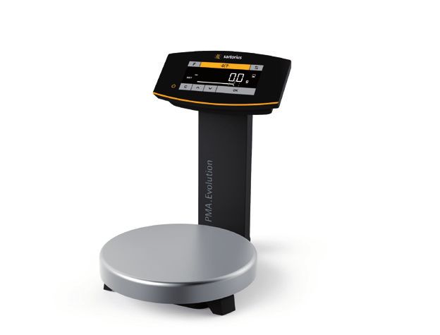
English

ttOnly operate the device when it is safe and in perfect
  working order.                                                     3        Installation
ttImmediately disconnect the damaged device from the
  power.
ttHave any malfunctions or damage repaired immediately               3.1     Scope of Delivery
  by Sartorius Service personnel.
                                                                     Item                                                   Quantity
2.6    Work on the Electrical Equipment of the                       Large weighing pan: d 233 mm                           1
       Device                                                        USB cable                                              1
Work on and modifications to the electrical equipment of the         AC adapter YPS06-USB                                   Optional
device may only be carried out by Sartorius Service personnel.       Installation instructions                              x
The device may only be opened by Sartorius Service personnel.
           Seal on Scales Verified for Use in Legal Metrology
                                                                     3.2     Unpacking
           Legislation requires that a seal be affixed to
           verified scales. On Sartorius devices, this seal takes
           the form of a sticker with the “Sartorius” logo. If       Procedure
           the seal is removed, the validity of verification will    ttOpen the packaging, making sure to remove all parts
           become void and you must have your scale                     carefully.
           re-verified. For verified scales for use in the EEA,      ttAfter unpacking the device, check it immediately for any
           the declaration of conformity set out in the                 external damage.
           calibration and supplied here shall apply. Please         ttIf the device is stored temporarily: Store the device
           keep it in a safe place.                                     according to the ambient conditions (ambient conditions
                                                                        see Chapter “8.1 General Data,” page 10).
                                                                     ttSave all parts of the original packaging for any future
2.7    Personal Protective Equipment                                    transport. All cables should be unplugged when
                                                                        transporting.
Personal protective equipment protects against risks arising
from the material being processed.
                                                                     3.3     Selecting a Setup Location
ttWhen the workplace or the process in which the device
  is used requires personal protective equipment: Wear               Select the right setup location:
  personal protective equipment.                                     −− Set up the device on a stable, even surface that is not
                                                                        exposed to vibrations.
                                                                     −− Maintain free access to the device at all times.
2.8    Safety Instructions Concerning Operation
       of the Device                                                 Choose a location that is not subject to the following negative
−− Take care that the glass panel of the operating display is not    influences:
   damaged (e.g., by falling objects, impact, or extreme             −−   Heat (heater or direct sunlight)
   pressure). If the glass panel is damaged, disconnect the device   −−   Drafts from open windows, AC systems, and doors
   from the power supply immediately.                                −−   Extreme vibrations during weighing
−− The surface of the operating display should not be touched        −−   Heavy “traffic areas” (personnel)
   with pointed, sharp, hard, or rough objects. You should only      −−   Extremely high humidity
   use the touch pen provided or your fingertips. Do not use         −−   Electromagnetic fields
   parts of clothing (e.g., sleeves) or sponges for cleaning         −−   Extremely dry air
   because these can scratch the surface (e.g., due to rivets or
   buttons in the sleeve or sand in the sponge).                     Acclimatization
−− Avoid generating static electricity on the glass panel of the     Condensation from humidity can form on the surfaces of a
   operating display and plastic casing.                             cold device when it is brought into a warm area. You should
                                                                     therefore let a device that has been disconnected from its
               Danger of Damage to the Scale!                        power source acclimatize for approximately 2 hours before
               Never close a paint can using a hammer while          reconnecting it to the supply voltage.
               it is still on the weighing pan.
               When closing, place the paint can on a firm,
               stable surface.

                                                                                               Installation Instructions EVO1Y1        5
3.4 Installing the Scale Inspections should be carried out at least once every three
years. The applicable requirements and guidelines should
also be observed during operation.
NOTICE Establish a low resistance connection from the scale to
The device must be disconnected from the power supply for
a customer-supplied equipotential bonding conductor
all assembly work.
connection via the equipotential bonding conductor
connection on the device using a suitable grounding cable
3.4.1 Place the weighing pan on the scale with a gauge of at least 4 mm2 (not included).
Installation must be carried out properly by trained personnel
ttPlace the weighing pan onto the and according to commonly accepted technical standards.
scale from above. The system should only be operated for the first time when it
is certain that the area is not potentially explosive.
If deviations are evident during startup due to transport
damage (e.g., no display, no backlighting), disconnect the
scale from the power supply and contact Sartorius Service.
Connect the scale to the equipo-
tential bonding conductor using
an equipotential bonding cable
3.4.2 Connecting the Scale
with a gage of at least 4 mm².
ttInsert the USB cable into the ttConnect the cable lug of the
socket on the back of the equipotential bonding cable to
display. the grounding terminal of the
scale.
ttConnect the equipotential
bonding cable to the custom-
er-supplied equipotential
1 ttLoosen the screw (1) on the lock. bonding conductor.
ttSwivel the lock over the USB
cable.
ttRe-tighten the lock screw. 3.6 Supply Voltage
Required qualifications: Electrician
The scale is connected to the power supply via a PC/notebook
or using the optional AC adapter YPS06-USB (see Chapter “6
ttLay the USB cable through the Accessories,” page 9), which is supplied with mains
cable holders on the back of the adapters for use in various countries.
scale.
NOTICE
−− Ensure that the voltage rating printed on the AC adapter is
identical to your local mains voltage (for connection data,
see Chapter “8.1 General Data”, page 21).
−− If the stated supply voltage or the plug design of the power
supply does not comply with your country's standard then
3.5 Connecting the Grounding Cable please inform your nearest Sartorius representative.
This explosion-protected system should be set up according
to commonly accepted technical standards. The applicable Power supply via the AC adapter is only required:
national electrical code and safety regulations for your −− When no PC or notebook is available.
particular country must be observed. −− In exceptional cases, when the output voltage of the USB
Before starting up the scale, a check must be carried out by interface of the PC or notebook is not sufficient.
or under the supervision of a qualified electrician to ensure
that the system is in good working order. 3.6.1 Installing the AC Adapter
Check whether or not the competent authorities (e.g. tt WARNING Lethal electric shock and equipment
industrial supervisory board) need to be informed. It is also damage due to incorrect power plug adapter! Only use
necessary to carry out inspections of the system during the country-specific power plug adapter. Never plug
operation. the power plug adapter into the socket when it is
Inspection intervals should be such that any significant disconnected from the power supply.
defects that may occur can be identified in good time.
6 Installation Instructions EVO1Y1English
ttUse the right mains adapter for your mains power supply: Connecting a PC/Notebook
ttInsert the USB cable into a USB socket on a PC or laptop.
Connecting an AC Adapter (Optional)
ttInsert the USB cable into the
AC adapter.
ttPlug the AC adapter into the
wall outlet (supply voltage).
3.7 Anti-theft Locking Device
ttIf required, secure the scale at
the back.
Mains adapter set YAK01
Bag Region/Country
a) transparent Europe/EU (except United Kingdom)
b) blue USA
c) yellow United Kingdom
Mains adapter set YAK02
3.8 Leveling
d) red Australia
Leveling for Models Verified for Use in Legal Metrology
e) turquoise South Africa
Only
f) white Argentina
Leveling the scale compensates for slant or unevenness at the
g) pink Brazil place of installation. The scale must be perfectly horizontal to
ensure consistent, reproducible weighing results.
Mains adapter set YAK03
The scale needs to be re-leveled and then adjusted if
h) light brown China necessary each time its setup location is changed.
i) black India
ttTurn the two leveling feet as
j) green Korea shown in the illustration until
12* the air bubble is centered within
ttPush (1) and slide (2) to insert 9* the circle of the level indicator.
the mains adapter required for −− Air bubble at “12 o'clock:” Turn
your power supply into the 6* both feet clockwise.
opening of the AC adapter. −− Air bubble at “3 o'clock:” Turn the
When doing this, the mains left foot clockwise and the right
adapter needs to lock into * o'clock foot counterclockwise.
position. −− Air bubble at “6 o'clock:” Turn
both feet counterclockwise.
−− Air bubble at “9 o'clock:” Turn the
Removing/Replacing left foot counterclockwise and
the Mains Adapter the right foot clockwise.
ttUnlock (1) and then remove the
mains adapter (2).
Installation Instructions EVO1Y1 73.9 Warm-up Time Cleaning the Device Housing
ttWipe off the housing with a slightly damp cloth. For more
Using a Scale Verified for Use in Legal Metrology: severe contamination, use a mild soap solution.
ttWipe the device with a soft cloth.
Ensure that there is a warm-up time of at least 24
hours after initial connection to the power supply. 4.2 Servicing
0 To ensure accurate results are To ensure the continued accuracy of your scale, we
delivered, the scale must warm up recommend scheduling regular servicing at least once a year.
for at least 30 minutes after initial Sartorius Service offers different service contracts with
connection to the power supply. maintenance intervals that are tailored to your needs.
Only then will the device have
A calibration certificate should always be issued as part of
reached the required operating
30 every maintenance session. Safety inspections of the AC
temperature.
adapter and its connections must be performed at appropriate
intervals by a qualified electrician (e.g., every 2 years).
4 Cleaning and
Maintenance 5 Disposal
4.1 Cleaning 5.1 Information on Decontamination
The operator is responsible for adhering to local legislation on
Before cleaning the AC adapter or the scale: Disconnect all
the proper declaration of transport and disposal and the
devices from the power supply.
proper disposal of the device.
WARNING Electrical Hazard from Voltage or
Current WARNING
Disconnect the AC adapter (if connected) from the mains. Risk of injury due to contaminated devices!
Unplug any connected data cables from the PC. Never open Devices contaminated with hazardous materials (NBC
the scale or the AC adapter. The parts contained in these contamination) will not be accepted for repair or disposal.
devices cannot be cleaned, repaired, or replaced by the user.
NOTICE 5.1.1 Information on Disposal
Do not clean the following parts with acetone or aggressive
cleaning agents: The device and its accessories do not belong in your regular
−− Mains socket household waste, since they are made of high-grade materials
−− Data interface which can be recycled and reused. All parts must be disposed
−− Labels, and all other plastic parts of properly by disposal facilities. The packaging is made of
environmentally friendly materials that can be used as
secondary raw materials.
Procedure
ttDisconnect the device from the power supply. 5.1.2 Disposal
ttNOTICE Make sure that no liquid or dust gets into the
scale or the AC adapter.
Requirements
ttNOTICE Corrosion or damage to the device due to
unsuitable cleaning agents! The device has been decontaminated.
ttDo not use corrosive, chloride-containing, and
aggressive cleaning agents. Procedure
ttDo not use cleaning agents that contain abrasive ttDispose of the device. Follow the disposal instructions
ingredients, e.g. scouring agents, steel wool. on our website (www.sartorius.com).
ttOnly use soft brushes and cloths for cleaning. ttDispose of the packaging in accordance with local
ttDo not use solvent-based cleaning agents. government regulations.
Cleaning the Control Panel
ttBefore cleaning the control panel: Turn off the device as
touching the screen could trigger unwanted inputs.
8 Installation Instructions EVO1Y1English
6 Accessories 7 Serial Number Coding
Accessories Order Number
USB connection cable YCC01-0040M5
Power supply (5 V/900 mA) YPS06-USB
Power plug adapter set for YPS06-USB YAK01
−− USA and Japan
−− Europe/EU
−− United Kingdom
Power plug adapter set for YPS06-USB YAK02
−− Australia
−− South Africa
−− Argentina
−− Brazil
Power plug adapter set for YPS06-USB YAK03
−− India
−− Korea
−− China
Equipotential bonding cable, 2 m YCC01-X046M2
The manufacture date of this device is encoded in the serial
In-use cover for the control panel, YDC03PMA10
number. The format is as follows:
pack of 10
In-use cover for the support arm, YDC03PMA-CO10 YMM x x x x x
pack of 10 Y Year
In-use cover for weighing pan, YDC03PMA-WP10 3 2014-2020
pack of 10 4 2021-2027
CAL weight 5 2028-2034, etc.
−− 5 kg, accuracy class F2 YCW654-AC-00
−− 2 kg, accuracy class F2 YCW624-AC-00 The Y column indicates the year group, which covers a period
of 7 years. Within each year group, the months (M M) are
−− 1 kg, accuracy class F2 YCW614-AC-00
counted up from 13.
Year: 2015 2016 2017 2018 2019 ...
MM: 25-36 37-48 49-60 61-72 73-84 ...
Example:
328xxxxx (April 2015). “xxxxx” is a consecutive number that
resets and starts from one every month.
Installation Instructions EVO1Y1 98 Technical Data
8.1 General Data
Specification Unit Value
ID code (explosion protection) II 3G Ex ic nA IIB T4 Gc as per EC Type Examination Certificate no.
FM15ATEX0008X
Supply voltage only via USB interface or Sartorius AC adapter YPS06-USB
Input voltage VDC +4.5–5.0
Power consumption W 2.0 (typically)
Further data IP40 in accordance with EN 60529/IEC 60529
Ambient conditions
The technical specifications apply under the following ambient conditions:
Environment For indoor use only.
Ambient temperature* +10°C to +30°C
Operational capability °C Guaranteed between +5 and +40
Storage and shipping °C -10 to +60
Relative humidity** % 15 to 80 for temperatures up to 30°C non-condensing, decreasing
linearly to 50% relative humidity at 40°C
Electromagnetic compatibility In accordance with EN 61326-1/IEC61326-1
Electrical equipment for measurement, control and laboratory use –
EMC requirements – Part 1: General requirements
Interference resistance Basic requirements
Transient emissions Class B
Suitable for use in residential areas and areas that are connected to a
low voltage network that also supplies residential buildings.
Verified scales in accordance with EU requirements comply with the
requirements of Council Directive 2014/31/EC with EN 45501:2015 and
OIML R76:2006.
* For verified scales in accordance with EU requirements, refer to the
information on the scale.
** For verified scales in accordance with EU requirements, the legal
regulations apply.
Available application programs Recalculation, factor calculation, formula
AC adapter YPS06-USB
USB power plug (5 V/900 mA) Type FW7712 (manufacturer's certificate)
Primary 100–240 V~, -10%/+10%, 50–60 Hz, 0.125 A
Secondary 5 VDC, ± 5%, 900 mA (max.)
Further data Protection class II
IP40 in accordance with EN 60529/IEC 60529
10 Installation Instructions EVO1Y1English
8.2 Model-specific Data
Specification Unit Value
PMA.Evolution
EVO1Y1
Weighing capacity g 7500/999.95
Readability g 0.1/0.05
Tare range (subtractive) g -7500
External adjustment weight / kg 1, 2, 5 /
accuracy class F2 or better
Size of weighing pan d mm 233
Net weight kg 2.4
8.3 Verified Models with EC Type Approval Certificate: Model-Specific Technical Specifications
Specification Unit Value
Model PMA.Evolution, EVO1Y
Accuracy class �
Type PMA-EV
Weighing capacity max. g 7500
Scale interval d g 0.1
Verification scale interval e g 1
Temperature range +10°C to +30°C
Tare equalization range (subtractive) < 100% from max. weighing capacity
9 EU Declaration of Conformity
The attached Declaration of Conformity hereby confirms compliance of the device with the directives cited.
For verified scales for use in the EEA, the declaration of conformity set out in the conformity assessment (calibration) shall apply.
Please keep it in a safe place.
Installation Instructions EVO1Y1 11Inhalt 1.2.1 Warnungen
1 Über dieses Dokument . . . . . . . . . . . . . . . . . . . . . . . . . . . . . . . . . . 12 WARNUNG
1.1 Gültigkeit . . . . . . . . . . . . . . . . . . . . . . . . . . . . . . . . . . . . . . . . . . . . 12 Kennzeichnet eine Gefährdung, die Tod oder schwere Körper-
1.2 Darstellungsmittel . . . . . . . . . . . . . . . . . . . . . . . . . . . . . . . . . . . 12 verletzung zur Folge haben kann, wenn sie nicht vermieden
wird.
2 Sicherheit . . . . . . . . . . . . . . . . . . . . . . . . . . . . . . . . . . . . . . . . . . . . . . . . 12
2.1 Bestimmungsgemäße Verwendung . . . . . . . . . . . . . . . . . 12 VORSICHT
2.2 Explosionsschutz . . . . . . . . . . . . . . . . . . . . . . . . . . . . . . . . . . . . 13 Kennzeichnet eine Gefährdung, die eine mittelschwere oder
2.3 Personalqualifikation . . . . . . . . . . . . . . . . . . . . . . . . . . . . . . . . 13 leichte Körperverletzung zur Folge haben kann, wenn sie nicht
2.4 Bedeutung dieser Anleitung . . . . . . . . . . . . . . . . . . . . . . . . 13 vermieden wird.
2.5 Einwandfreiheit des Geräts . . . . . . . . . . . . . . . . . . . . . . . . . . 13
2.6 Arbeiten an der elektrischen Ausrüstung ACHTUNG
des Geräts . . . . . . . . . . . . . . . . . . . . . . . . . . . . . . . . . . . . . . . . . . . 14 Kennzeichnet eine Gefährdung, die Sachschäden zur Folge
2.7 Persönliche Schutzausrüstung . . . . . . . . . . . . . . . . . . . . . . 14 haben kann, wenn sie nicht vermieden wird.
2.8 Sicherheitshinweise zur Bedienung des Gerätes . . . . 14
3 Installation . . . . . . . . . . . . . . . . . . . . . . . . . . . . . . . . . . . . . . . . . . . . . . . 14 1.2.2 Weitere Darstellungsmittel
3.1 Lieferumfang . . . . . . . . . . . . . . . . . . . . . . . . . . . . . . . . . . . . . . . . 14
3.2 Auspacken . . . . . . . . . . . . . . . . . . . . . . . . . . . . . . . . . . . . . . . . . . . 14 t Handlungsanweisung: Beschreibt Tätigkeiten, die
3.3 Aufstellort wählen . . . . . . . . . . . . . . . . . . . . . . . . . . . . . . . . . . 14 ausgeführt werden müssen.
3.4 Waage montieren . . . . . . . . . . . . . . . . . . . . . . . . . . . . . . . . . . . 15 y Ergebnis: Beschreibt das Ergebnis der ausgeführ-
3.5 Erdung anschließen . . . . . . . . . . . . . . . . . . . . . . . . . . . . . . . . . 15 ten Tätigkeiten.
3.6 Spannungsversorgung . . . . . . . . . . . . . . . . . . . . . . . . . . . . . . . 15
−− Texte, die dieser Markierung folgen, sind Aufzäh-
3.7 Diebstahlsicherung . . . . . . . . . . . . . . . . . . . . . . . . . . . . . . . . . . 16
lungen.
3.8 Nivellieren . . . . . . . . . . . . . . . . . . . . . . . . . . . . . . . . . . . . . . . . . . . 16
3.9 Anwärmzeit . . . . . . . . . . . . . . . . . . . . . . . . . . . . . . . . . . . . . . . . . 17 Dieses Symbol gibt einen Hinweis für den eich-
pflichtigen Verkehr für konformitätsbewertete
4 Reinigung und Wartung . . . . . . . . . . . . . . . . . . . . . . . . . . . . . . . . 17 (geeichte) Waagen.
4.1 Reinigen . . . . . . . . . . . . . . . . . . . . . . . . . . . . . . . . . . . . . . . . . . . . . 17 Im weiteren Text steht der Begriff ‚geeicht‘ für
4.2 Warten . . . . . . . . . . . . . . . . . . . . . . . . . . . . . . . . . . . . . . . . . . . . . . 17 den Fachausdruck konformitätsbewertet.
5 Entsorgung . . . . . . . . . . . . . . . . . . . . . . . . . . . . . . . . . . . . . . . . . . . . . . . 17
5.1 Hinweise zur Dekontamination . . . . . . . . . . . . . . . . . . . . . 17
Abbildungen der Bedienanzeige
6 Zubehör . . . . . . . . . . . . . . . . . . . . . . . . . . . . . . . . . . . . . . . . . . . . . . . . . . 18
Die Abbildungen in dieser Anleitung basieren auf „Stan-
7 Codierung der Seriennummer . . . . . . . . . . . . . . . . . . . . . . . . . . 18 dard“-Waagen. Bei den geeichten Waagen können einige
Anzeigedarstellungen und Protokolle von den Abbildungen
8 Technische Daten . . . . . . . . . . . . . . . . . . . . . . . . . . . . . . . . . . . . . . . . 19
etwas abweichen. Wo dies für den Betrieb von Bedeutung ist,
8.1 Allgemeine Daten . . . . . . . . . . . . . . . . . . . . . . . . . . . . . . . . . . . 19
werden die Unterschiede im Text erläutert.
8.2 Modellspezifische Daten . . . . . . . . . . . . . . . . . . . . . . . . . . . . 20
8.3 Geeichte Modelle mit EG-Bauartzulassung:
Modellspezifische technische Daten . . . . . . . . . . . . . . . . 20
9 EU-Konformitätserklärung . . . . . . . . . . . . . . . . . . . . . . . . . . . . . 20
2 Sicherheit
2.1 Bestimmungsgemäße Verwendung
1 Über dieses Dokument Diese Waage ist nur bestimmt für das Mischen von Farben und
Lacken. Die Waage wird im explosionsgefährdeten Bereich der
Zone 2 eingesetzt. Zur Aufnahme der Materialien müssen
1.1 Gültigkeit
geeignete Gefäße verwendet werden.
Diese Anleitung gilt für Farbmischwaagen der Modelle: Die Waage darf sowohl über das Display im Stand-Alone-Be-
trieb, als auch mit Hilfe einer auf dem PC installierten
−− EVO1Y Applikationssoftware (z. B. eine Farbmischapplikation des
Lackherstellers) gesteuert werden. Die Waage wird dabei über
1.2 Darstellungsmittel ein USB-Kabel mit dem außerhalb des explosionsgefährdeten
Bereiches aufgestellten Personalcomputer / Notebook verbun-
Der in der Anleitung verwendete Begriff Gerät bezeichnet den. Die Angaben zum Explosionsschutz im „2.2 Explosions-
immer die Kombination Waage, Netzgerät und Ex-Link schutz“, Seite 13 sind zu beachten.
Konverter.
12 Installationsanleitung EVO1Y1Deutsch
Die Anleitung ist Teil des Geräts. Das Gerät ist ausschließlich Wenn einzelne Tätigkeiten durch andere Zielgruppen oder den
für den Einsatz gemäß dieser Anleitung bestimmt. Sartorius Service ausgeführt werden müssen: Die benötigte
Qualifikation ist bei der Beschreibung der Tätigkeit
Jede weitere Verwendung gilt als nicht bestimmungsgemäß.
angegeben.
Wenn das Gerät nicht bestimmungsgemäß eingesetzt wird:
Die Schutzvorrichtungen des Geräts können beeinträchtigt Zielgruppe Kenntnisse und Zuständigkeiten
werden. Dies kann zu Personenschäden und Sachschäden
Bediener Der Bediener ist mit dem Betrieb des Geräts und
führen.
den damit verbundenen Arbeitsprozessen ver-
Bei Verwendung in Anlagen und Umgebungsbedingungen mit traut. Er kennt die Gefahren, die bei Arbeiten
erhöhten Sicherheitsanforderungen die Auflagen und Bestim- mit dem Gerät auftreten können und kann diese
mungen Ihres Landes beachten. Gefahren vermeiden.
Der Bediener ist in den Betrieb des Geräts ein-
Einsatzbedingungen für das Gerät gewiesen. Die Einweisung erfolgt im Rahmen
der Inbetriebnahme und wird durch den
Das Gerät nur in Gebäuden verwenden. Betriebsingenieur / Laborleiter oder den Betrei-
Das Gerät nur mit den Ausstattungen und unter Betriebsbe- ber des Geräts durchgeführt.
dingungen einsetzen wie sie in den Technischen Daten Betriebsin- Der Betriebsingenieur / Laborleiter entscheidet
beschrieben sind. Das Gerät nicht umbauen oder technisch genieur / über den Einsatz und die Parametrierung des
verändern. Laborleiter Geräts.
Das Gerät sowie das von Sartorius gelieferte Zubehör nicht Der Betriebsingenieur / Laborleiter ist in den
extremen Temperaturen, aggressiven chemischen Dämpfen, Betrieb des Geräts eingewiesen. Die Einweisung
Feuchtigkeit, Stößen, Vibrationen oder starken elektromagne- erfolgt im Rahmen der Inbetriebnahme und
tischen Feldern aussetzen. Einsatzbedingungen gemäß den wird durch den Sartorius Service oder den
Technischen Daten einhalten! Betreiber durchgeführt.
Die Verbindungskabel zwischen den Geräten sowie die Elektro- Die Elektrofachkraft kann aufgrund ihrer fachli-
Ummantelung der Litzen der inneren Verdrahtungen bestehen fachkraft chen Ausbildung, Kenntnisse und Erfahrungen
aus PVC-Materialien. Chemikalien, die diese Materialien sowie Kenntnis der einschlägigen Bestimmun-
angreifen, müssen von diesen Leitungen ferngehalten werden. gen die ihr übertragenen Arbeiten beurteilen
und mögliche Gefahren erkennen.
2.2 Explosionsschutz Betreiber Der Betreiber des Geräts ist für die Einhaltung
der Sicherheits- und Arbeitsschutzbestimmun-
gen zuständig.
Verwendung im Geltungsbereich der europäischen Der Betreiber muss sicherstellen, dass alle Perso-
ATEX-Richtlinie: nen, die am Gerät arbeiten, Zugang zu den rele-
−− Bei dem Modell EVO1Y1 handelt es sich gemäß Richtlinie vanten Informationen haben und in die Arbeit
2014/34/EU um ein Gerät der Kategorie 3, das für den am Gerät eingewiesen sind.
Einsatz im explosionsgefährdeten Bereich der Zone 2
geeignet ist.
−− Die Kennzeichnungen der Geräte sind den EU-Type 2.4 Bedeutung dieser Anleitung
Examination Certificates (EU-Baumusterprüfbescheinigun-
gen) im Kapitel „18.2 Zulassungen Explosionsschutz“, Seite Die Nichtbeachtung der Anleitung kann ernste Folgen haben,
59 zu entnehmen. z. B. Gefährdung von Personen durch elektrische, mechanische
−− Die Sicherheitshinweise gemäß der Zeichnung 2021460 ab oder chemische Einflüsse.
Seite 59 sind zu befolgen. ttVor allen Arbeiten am Gerät die Anleitung aufmerksam
und vollständig durchlesen.
Verwendung in Australien / Neuseeland: ttBei Verlust der Anleitung Ersatz anfordern oder die
−− Das IECEx Certificate of Conformity IECEx FME 15.0004X aktuelle Anleitung von der Sartorius-Internetseite herun-
sowie die Sicherheitshinweise gemäß der Zeichnung terladen (www.sartorius.com).
2021460 ab Seite 59 sind zu befolgen. ttDie Informationen aus der Anleitung müssen für alle
Personen verfügbar sein, die am Gerät arbeiten.
2.3 Personalqualifikation
2.5 Einwandfreiheit des Geräts
Diese Anleitung richtet sich an die unten genannten Zielgrup-
pen. Alle Personen, die am Gerät arbeiten, müssen über die Ein beschädigtes Gerät kann zu Fehlfunktionen führen oder
genannten Kenntnisse und Zuständigkeiten verfügen. schwer erkennbare Gefährdungen hervorrufen.
Wenn bei den beschriebenen Tätigkeiten in dieser Anleitung
keine Qualifikation angegeben ist: Die beschriebenen Tätig-
keiten richten sich an die Zielgruppe „Bediener“.
Installationsanleitung EVO1Y1 13ttDas Gerät nur in sicherheitstechnisch einwandfreiem
Zustand betreiben. 3 Installation
ttBeschädigtes Gerät sofort spannungslos schalten.
ttBeschädigungen umgehend durch den Sartorius Service
beheben lassen. 3.1 Lieferumfang
2.6 Arbeiten an der elektrischen Ausrüstung Artikel Menge
des Geräts Waagschale groß: d 233 mm 1
USB Kabel 1
Jegliche Arbeiten und Modifikationen an der elektrischen
Ausrüstung des Geräts dürfen nur vom Sartorius Service Netzgerät YPS06-USB optional
vorgenommen werden. Das Gerät darf nur vom Sartorius Installationsanleitung x
Service geöffnet werden.
Versiegelungsmarke an geeichten Varianten
3.2 Auspacken
Der Gesetzgeber fordert eine Versiegelung der
geeichten Waage. Diese Versiegelung erfolgt
mittels einer Klebemarke mit Namenszug „Sarto- Vorgehen
rius“. Wird sie entfernt, erlischt die Eichgültigkeit ttÖffnen Sie die Verpackung und entnehmen Sie vorsichtig
und die Waage muss geeicht werden. Bei geeich- alle Teile.
ten Waagen für den Einsatz im EWR gilt die bei ttÜberprüfen Sie das Gerät nach dem Auspacken sofort auf
der Eichung ausgestellte und der Waage beige- äußere Beschädigungen.
legte Konformitätserklärung. Bitte unbedingt ttWenn das Gerät zwischengelagert wird: Das Gerät gemäß
aufbewahren. den Umgebungsbedingungen lagern (Umgebungsbedin-
gungen siehe Kapitel „8.1 Allgemeine Daten“, Seite 19
ttBewahren Sie alle Teile der Originalverpackung für einen
2.7 Persönliche Schutzausrüstung eventuellen Rücktransport auf. Lassen Sie beim Versand
keine Kabel stecken!
Die persönliche Schutzausrüstung schützt vor Gefährdungen
durch die verarbeiteten Materialien.
3.3 Aufstellort wählen
ttWenn der Arbeitsbereich oder der Prozess, in dem das
Gerät eingesetzt wird, eine persönliche Schutzausrüstung Den richtigen Standort wählen:
erfordert: Die persönliche Schutzausrüstung tragen. −− Das Gerät auf eine stabile, erschütterungsarme, gerade Fläche
stellen.
−− Zugang zu dem Gerät jederzeit freihalten.
2.8 Sicherheitshinweise zur Bedienung des
Gerätes Bei der Aufstellung Standorte mit ungünstigen Einflüssen
−− Die Glasscheibe des Bediendisplays nicht beschädigen (z. B. vermeiden:
durch herabfallende Gegenstände, Schläge oder starken −− Hitze (Heizung, Sonneneinstrahlung)
Druck). Wird die Glasscheibe beschädigt, ist das Gerät sofort −− Direkter Luftzug durch offene Fenster, Klimaanlagen und
vom Netz zu trennen! Türen
−− Die Oberfläche des Bediendisplays nicht mit spitzen, scharfen, −− Erschütterungen während der Messung
harten oder rauen Gegenständen berühren, sondern aus- −− Kein „Personendurchgangsverkehr“
schließlich mit einem dafür vorgesehenen Touchpen oder mit −− Extrem hohe Luftfeuchtigkeit
den Fingerspitzen. Zum Reinigen keinesfalls Teile der Kleidung −− Elektromagnetische Felder
(z. B. Jackenärmel) oder Schwämme verwenden, da diese die −− Extrem trockene Luft
Oberfläche zerkratzen können (z. B. durch Nieten oder Knöpfe
im Jackenärmel oder Sand in Schwämmen). Akklimatisieren
−− Elektrostatische Aufladung der Glasscheibe des Bediendisplays Wenn ein kaltes Gerät in eine warme Umgebung gebracht
und des Kunststoffgehäuses vermeiden. wird kann dies zu Kondensation von Luftfeuchtigkeit führen
(Betauung). Daher akklimatisieren Sie das vom Netz getrennte
Beschädigungsgefahr der Waage! Gerät ca. 2 Stunden, bevor Sie es wieder an die Versorgungs-
Verschließen Sie nie die Farbdose mit einem spannung anschließen.
Hammer, solange diese auf der Waagschale
steht.
Stellen Sie die Farbdose zum Verschließen auf
einen festen stabilen Untergrund.
14 Installationsanleitung EVO1Y1Deutsch
3.4 Waage montieren durchzuführen. Während des Betriebes sind die entsprechen-
den Auflagen und Richtlinien zu erfüllen.
Die Waage mit einem geeigneten Erdungskabel von mindes-
ACHTUNG tens 4 mm2 Querschnitt (nicht im Lieferumfang enthalten)
Für alle Montagearbeiten muss das Gerät von der Spannungs-
niederohmig über die am Gerät vorhandenen Potenzialaus-
versorgung getrennt sein.
gleichsanschluss an einen kundenseitigen Potenzialausgleichs-
anschluss anschließen.
3.4.1 Waagschale aufsetzen Die Installation muss von einer dafür ausgebildeten Fachkraft
vorschriftsmäßig und nach den Regeln der Technik durchge-
ttSetzen Sie die Waagschale von führt werden. Die Anlage erstmalig nur dann in Betrieb
oben auf die Waage auf. nehmen, wenn sichergestellt ist, dass der Bereich nicht
explosionsgefährdet ist.
Zeigen sich bei dieser Inbetriebnahme durch Transportschäden
Abweichungen (z. B. keine Anzeige, keine Hintergrundbeleuch-
tung), so ist die Waage vom Netz zu trennen und der Sartorius
Service zu informieren.
Verbinden Sie die Waage mit
einem Potenzialausgleichskabel
3.4.2 Waage anschließen
von mindestens 4 mm² Querschnitt
ttStecken Sie das USB-Anschluss- mit dem Potenzialausgleich.
kabel auf der Rückseite des ttSchließen Sie den Kabelschuh
Displays in die Buchse. des Potenzialausgleichskabels
an die Erdungsklemme der
Waage an.
ttSchließen Sie das Potenzialaus-
gleichskabel an den kundensei-
1 ttLösen Sie die Schraube (1) der tigen Potenzialausgleich an.
Verriegelung.
ttSchwenken Sie die Verriegelung
über das USB-Kabel. 3.6 Spannungsversorgung
ttZiehen Sie die Schraube der Benötigte Qualifikation: Elektrofachkraft
Verriegelung an.
Die Spannungsversorgung der Waage erfolgt über einen
PC / Notebook oder durch das optionale Netzgerät YPS06-USB
(siehe Kapitel „6 Zubehör“, Seite 18), das mit verschiedenen
ttVerlegen Sie das USB-Anschluss-
länderspezifischen Netzadaptern geliefert wird.
kabel durch die Kabelhalter auf
der Rückseite der Waage.
ACHTUNG
−− Der auf dem Netzgerät aufgedruckte Spannungswert muss
mit der lokalen Netzspannung übereinstimmen (Anschlussda-
ten siehe Kapitel „8.1 Allgemeine Daten“, Seite 21).
−− Sollte die angegebene Netzspannung oder die Steckerausfüh-
rung des Netzgerätes nicht der verwendeten Ländernorm
entsprechen, verständigen Sie bitte die nächste Sartorius-Ver-
3.5 Erdung anschließen
tretung.
Die explosionsgeschützte Anlage nach den anerkannten
Regeln der Technik errichten. Dabei sind die entsprechenden Die Spannungsversorgung über das Netzgerät wird nur
nationalen Gesetze/Vorschriften zu beachten. benötigt:
Vor Inbetriebnahme der Waage muss der ordnungsgemäße −− wenn kein PC oder Notebook vorhanden ist.
Zustand durch eine Elektrofachkraft oder unter Leitung und −− in Ausnahmefällen die Ausgangsspannung der USB-Schnitt-
Aufsicht einer Elektrofachkraft überprüft werden. stelle des PCs oder Notebooks nicht ausreichend ist.
Prüfen Sie, ob die zuständigen Behörden (z. B. Gewerbeauf-
3.6.1 Netzgerät montieren
sichtsamt) informiert werden müssen. Auch während des
Betriebes sind Prüfungen der Anlage erforderlich. tt WARNUNG Tödliche Stromschläge und Geräteschäden
Die Fristen dazu sind so zu bemessen, dass entstehende durch falsche Netzsteckeradapter! Nur den länderspezifi-
Mängel, mit denen gerechnet werden muss, rechtzeitig schen Netzsteckeradapter verwenden. Den Netzsteckerad-
erkannt werden. Die Prüfungen sind mindestens alle drei Jahre apter nie getrennt vom Netzgerät in die Steckdose stecken.
Installationsanleitung EVO1Y1 15ttVerwenden Sie den zu Ihrem Stromnetz passenden Anschluss an Personalcomputer / Notebook
Netzadapter: ttStecken Sie das USB-Anschlusskabel in eine USB-Buchse
(z. B. Personalcomputer, Laptop).
Anschluss an Netzgerät (optional)
ttStecken Sie das USB-Anschluss-
kabel in das Netzgerät.
ttStecken Sie das Netzgerät in
eine Steckdose (Netzspannung)
3.7 Diebstahlsicherung
ttSichern Sie die Waage bei
Bedarf an der Rückseite.
Netzadapterset YAK01
Beutel Region/Land
a) transparent Europa/EU (außer Großbritannien)
b) blau USA
c) gelb Großbritannien
Netzadapterset YAK02
3.8 Nivellieren
d) rot Australien Nivellieren bei konformitätsbewerteten (geeichten)
e) türkis Südafrika Modellen
f) weiß Argentinien Mit der Nivellierung der Waage können Neigungen am
Aufstellort der Waage ausgeglichen werden. Eine exakte
g) rosa Brasilien waagerechte Stellung der Waage gewährleistet genaue
Netzadapterset YAK03 Wägeergebnisse.
Die Waage muss nach jedem Standortwechsel neu nivelliert
h) hellbraun China
und danach gegebenenfalls justiert werden.
i) schwarz Indien
j) grün Korea ttDrehen Sie die beiden Fuß-
schrauben gemäß Abbildung,
12* bis die Luftblase der Libelle in
ttDrücken (1) und schieben (2) der Kreismitte steht.
Sie den für Ihre Stromversor- 9*
−− Luftblase bei »12 Uhr«: beide
gung erforderlichen Netzadap- 6* Fußschrauben im Uhrzeigersinn
ter in die Öffnung des Netzge- drehen.
räts. −− Luftblase bei »3 Uhr«: linke
Der Netzadapter muss dabei * Uhr Fußschraube im Uhrzeigersinn,
einrasten. rechte Fußschraube gegen den
Uhrzeigersinn drehen.
−− Luftblase bei »6 Uhr«: beide
Netzadapter
Fußschrauben gegen den
demontieren / tauschen
Uhrzeigersinn drehen.
ttEntriegeln (1) Sie den Netz −− Luftblase bei »9 Uhr«: linke
adapter und ziehen (2) Sie Fußschraube gegen den Uhr
ihn ab. zeigersinn, rechte Fußschraube im
Uhrzeigersinn drehen.
16 Installationsanleitung EVO1Y1Deutsch
3.9 Anwärmzeit Gerätegehäuse reinigen
ttDas Gehäuse mit einem leicht feuchten Reinigungstuch
Geeichte Waagen im eichpflichtigen Verkehr abwischen. Für stärkere Verschmutzungen eine milde
einsetzen: Seifenlauge verwenden.
Anwärmzeit von mindestens 24 Stunden einhalten ttDas Gerät danach mit einem weichem Tuch abwischen.
nach erstmaligem Anschluss an das Stromnetz.
4.2 Warten
0 Um genaue Resultate zu liefern,
benötigt die Waage eine Anwärm- Um die fortdauernde Messsicherheit Ihrer Waage zu gewähr-
zeit von mindestens 30 Minuten leisten, empfehlen wir die regelmäßige, mindestens jährliche
nach erstmaligem Anschluss an die Wartung. Der Sartorius Service bietet Ihnen hierzu unter-
Spannungsversorgung. Erst dann schiedliche Wartungsverträge an, die wir individuell an Ihre
hat das Gerät die notwendige Bedürfnisse anpassen.
30 Betriebstemperatur erreicht.
Im Rahmen jeder Wartung sollte immer ein Kalibrierzertifikat
erstellt werden. Lassen Sie eine sicherheitstechnische Überprü-
fung des Netzgerätes und dessen Anschlüsse in angemessenen
4 Reinigung und Wartung Abständen von einer Elektrofachkraft durchführen (z. B. alle
2 Jahre).
4.1 Reinigen
Vor Reinigen des Netzgerätes oder der Waage: Alle Geräte
5 Entsorgung
spannungslos schalten.
WARNUNG Gefahr durch elektrische Span- 5.1 Hinweise zur Dekontamination
nung! Der Betreiber ist für die Einhaltung der landesrechtlichen
Vorhandenes Netzgerät (optional) vom Netz trennen. Gegebe- Bestimmungen zur sachgerechten Deklaration bei Transport
nenfalls angeschlossenes Datenkabel am PC abziehen. Öffnen und Entsorgung und zur sachgerechten Entsorgung des Geräts
Sie niemals die Waage oder das Netzgerät. Diese enthalten verantwortlich.
keine Geräteteile, die vom Bediener gereinigt, repariert oder
ausgetauscht werden können.
WARNUNG
ACHTUNG Verletzungsgefahr durch kontaminierte Geräte!
Folgende Teile nicht mit Aceton oder aggressiven Reinigungs-
Mit gefährlichen Stoffen kontaminierte Geräte (ABC‑Konta-
mitteln reinigen:
mination) werden nicht zur Reparatur und Entsorgung
−− Netzsteckereingang
zurückgenommen.
−− Datenschnittstelle
−− Schilder sowie alle restlichen Kunststoffteile
5.1.1 Hinweise zur Entsorgung
Vorgehen Das Gerät und das Zubehör gehören nicht in den Hausmüll,
ttDas Gerät von der Spannungsversorgung trennen. denn sie sind aus hochwertigen Materialien hergestellt, die
ttACHTUNG Darauf achten, dass keine Flüssigkeit oder recycelt und wiederverwendet werden können. Alle Teile
Staub in die Waage oder in das Netzgerät gelangen. müssen durch Entsorgungseinrichtungen fachgerecht entsorgt
ttACHTUNG Korrosion oder Beschädigungen am Gerät werden. Die Verpackung besteht aus umweltfreundlichen
durch ungeeignete Reinigungsmittel! Materialien, die als Sekundärrohstoffe dienen können.
ttKeine ätzenden, chloridhaltigen und aggressiven
Reinigungsmittel verwenden. 5.1.2 Entsorgen
ttKeine Reinigungsmittel verwenden, die scheuernde
Bestandteile enthalten, z. B. Scheuermilch, Stahlwolle.
Voraussetzungen
ttZur Reinigung nur weiche Bürsten und Putzlappen
verwenden. Das Gerät ist dekontaminiert.
ttKeine lösemittelhaltigen Reinigungsmittel verwenden.
Vorgehen
Bedienfeld reinigen ttDas Gerät entsorgen. Dazu die Entsorgungshinweise auf
ttVor dem Reinigen des Bedienfeldes: Das Gerät ausschalten, unserer Internetseite (www.sartorius.com) beachten.
da durch die Berührung sonst ungewollt Eingaben ttDie Verpackung gemäß den landesrechtlichen Bestimmun-
erfolgen können. gen entsorgen.
Installationsanleitung EVO1Y1 176 Zubehör 7 Codierung der
Zubehör Bestellnummer
Seriennummer
USB-Verbindungskabel YCC01-0040M5
Netzgerät (5 V / 900 mA) YPS06-USB
Netzstecker-Adapterset für YPS06-USB YAK01
−− USA und Japan
−− Europa / EU
−− Großbritannien
Netzstecker-Adapterset für YPS06-USB YAK02
−− Australien
−− Südafrika
−− Argentinien
−− Brasilien
Netzstecker-Adapterset für YPS06-USB YAK03
−− Indien
−− Korea
−− China
Potenzialausgleichskabel, 2 m YCC01-X046M2
Arbeitsschutzhaube für Bedienfeld, YDC03PMA10
10er Pack
Das Herstelldatum des Gerätes ist in der Seriennummer codiert.
Arbeitsschutzhaube für Stativ, YDC03PMA-CO10 Die Struktur ergibt sich wie folgt:
10er Pack
JMM x x x x x
Arbeitsschutzhaube für Waagschale, YDC03PMA-WP10
10er Pack J Jahr
3 2014–2020
Justiergewicht
4 2021-2027
−− 5 kg, Genauigkeitsklasse F2 YCW654-AC-00
5 2028-2034 usw.
−− 2 kg, Genauigkeitsklasse F2 YCW624-AC-00
−− 1 kg, Genauigkeitsklasse F2 YCW614-AC-00
Die Jahresspalte J steht für die Jahresgruppennummer, die
einen Zeitraum von jeweils 7 Jahren definiert. Innerhalb jeder
Jahresgruppe werden die Monate (M M) von 13 an
hochgezählt.
Jahr: 2015 2016 2017 2018 2019 ...
MM: 25-36 37-48 49-60 61-72 73-84 ...
Beispiel:
328xxxxx (April 2015). „xxxxx“ ist eine fortlaufende Nummer,
die jeden Monat neu hochgezählt wird.
18 Installationsanleitung EVO1Y1Deutsch
8 Technische Daten
8.1 Allgemeine Daten
Angabe Einheit Wert
Kennzeichnung (Explosionsschutzart) II 3G Ex ic nA IIB T4 Gc lt. EG-Baumusterprüfung Nr. FM15ATEX0008X
Spannungsversorgung nur über USB Schnittstelle oder Sartorius Netzgerät YPS06-USB
Eingangsspannung VDC +4,5 bis 5,0
Leistungsaufnahme W 2,0 (typisch)
Weitere Daten IP40 gemäß EN 60529/IEC 60529
Umgebungsbedingungen
Die technischen Daten gelten bei folgenden Umgebungsbedingungen:
Umgebung Verwendung nur in Innenräumen
Umgebungstemperatur* +10 °C – +30 °C
Betriebsfähigkeit °C Gewährleistet zwischen +5 – +40
Lager und Transport °C –10 – +60
Relative Luftfeuchte** % 15 – 80 für Temperaturen bis zu 30 °C nicht-kondensierend,
linear abnehmend bis zu 50 % relativer Luftfeuchte bei 40 °C
Elektromagnetische Verträglichkeit gemäß EN 61326-1/IEC61326-1 Elektrische Mess-, Steuer-, Regel- und
Laborgeräte – EMV-Anforderungen – Teil 1: Allgemeine Anforderungen
Störfestigkeit Grundanforderungen
Störaussendung Klasse B
Geeignet für den Gebrauch im Wohnbereich und Bereichen, die direkt
an ein Niederspannungsnetz angeschlossen sind, das (auch) Wohnge-
bäude versorgt.
Geeichte Waagen gemäß EU entsprechen den Anforderungen der
EG-Richtlinie 2014/31/EU mit EN45501:2015 bzw. OIML R76:2006.
* Bei geeichten Waagen gemäß EU, siehe Angaben auf der Waage.
** Bei geeichten Waagen gemäß EU gelten die gesetzlichen Vorschriften
Wählbare Anwendungsprogramme Rekalkulation, Faktorverrechnung, Rezeptur
Netzgerät YPS06-USB
USB Steckernetzteil (5 V / 900 mA) Type FW7712 (Herstellerbezeichnung)
Primär 100 – 240 V~, –10 % / +10 %, 50 – 60 Hz, 0,125 A
Sekundär 5 VDC, ± 5 %, 900 mA (max.)
Weitere Daten Schutzklasse II
IP40 gemäß EN 60529/IEC 60529
Installationsanleitung EVO1Y1 198.2 Modellspezifische Daten
Angabe Einheit Wert
PMA.Evolution
EVO1Y1
Wägebereich g 7500 / 999,95
Ablesbarkeit g 0,1 / 0,05
Tarierbereich (subtraktiv) g –7500
Externer Justiergewichtswert / kg 1, 2, 5 /
Genauigkeitsklasse F2 oder besser
Größe der Waagschale d mm 233
Nettogewicht kg 2,4
8.3 Geeichte Modelle mit EG-Bauartzulassung: Modellspezifische technische Daten
Angabe Einheit Wert
Modell PMA.Evolution EVO1Y
Genauigkeitsklasse �
Bauart PMA-EV
Wägebereich Max g 7500
Ziffernschritt d g 0,1
Eichwert e g 1
Temperaturbereich +10°C – +30°C
Taraausgleichsbereich (subtraktiv) < 100% vom maximalen Wägebereich
9 EU-Konformitätserklärung
Mit der beigefügten Konformitätserklärung wird die Übereinstimmung des Geräts mit den benannten Richtlinien erklärt.
Bei geeichten Waagen für den Einsatz im EWR gilt die bei der Konformitätbewertung (Eichung) ausgestellte Konformitätserklä-
rung. Bitte unbedingt aufbewahren.
20 Installationsanleitung EVO1Y1Français
Table des matières 1.2.1 Avertissements
1 À propos de ce manuel . . . . . . . . . . . . . . . . . . . . . . . . . . . . . . . . . . . . 21 AVERTISSEMENT
1.1 Validité . . . . . . . . . . . . . . . . . . . . . . . . . . . . . . . . . . . . . . . . . . . . . . . . . 21 Signale un danger qui est susceptible d’entraîner la mort ou
1.2 Typographie . . . . . . . . . . . . . . . . . . . . . . . . . . . . . . . . . . . . . . . . . . . . 21 des blessures graves s’il n’est pas évité.
2 Sécurité . . . . . . . . . . . . . . . . . . . . . . . . . . . . . . . . . . . . . . . . . . . . . . . . . . . . . 21 ATTENTION
2.1 Utilisation conforme . . . . . . . . . . . . . . . . . . . . . . . . . . . . . . . . . . . 21 Signale un danger qui est susceptible d'entraîner des blessures
2.2 Protection contre les explosions . . . . . . . . . . . . . . . . . . . . . . . 22 moyennes ou légères s'il n'est pas évité.
2.3 Qualification du personnel . . . . . . . . . . . . . . . . . . . . . . . . . . . . 22
2.4 Importance de ce mode d’emploi . . . . . . . . . . . . . . . . . . . . . . 22 AVIS
2.5 État de l'appareil . . . . . . . . . . . . . . . . . . . . . . . . . . . . . . . . . . . . . . . 22 Signale un danger qui est susceptible de provoquer des
2.6 Travaux sur l’équipement électrique de l’appareil . . . . . 23 dommages matériels s’il n’est pas évité.
2.7 Équipement de protection individuelle . . . . . . . . . . . . . . . . 23
2.8 Consignes de sécurité concernant l’utilisation de 1.2.2 Autres signes typographiques
l’appareil . . . . . . . . . . . . . . . . . . . . . . . . . . . . . . . . . . . . . . . . . . . . . . . 23
3 Installation . . . . . . . . . . . . . . . . . . . . . . . . . . . . . . . . . . . . . . . . . . . . . . . . . . 23 t Instruction : décrit des actions qui doivent être
3.1 Contenu de la livraison . . . . . . . . . . . . . . . . . . . . . . . . . . . . . . . . 23 effectuées.
3.2 Déballage . . . . . . . . . . . . . . . . . . . . . . . . . . . . . . . . . . . . . . . . . . . . . . 23 Résultat : décrit le résultat des actions qui
y
3.3 Choisir le lieu d'installation . . . . . . . . . . . . . . . . . . . . . . . . . . . . 23 viennent d'être effectuées.
3.4 Monter la balance . . . . . . . . . . . . . . . . . . . . . . . . . . . . . . . . . . . . . 24
3.5 Raccorder la mise à la terre . . . . . . . . . . . . . . . . . . . . . . . . . . . . 24 −− Les textes qui suivent ce signe sont des énuméra-
3.6 Alimentation électrique . . . . . . . . . . . . . . . . . . . . . . . . . . . . . . . 24 tions.
3.7 Système antivol . . . . . . . . . . . . . . . . . . . . . . . . . . . . . . . . . . . . . . . . 25 Ce symbole donne une indication relative à l’utili-
3.8 Mettre à niveau . . . . . . . . . . . . . . . . . . . . . . . . . . . . . . . . . . . . . . . . 25 sation en métrologie légale de balances évaluées
3.9 Temps de préchauffage . . . . . . . . . . . . . . . . . . . . . . . . . . . . . . . . 26 conformes (approuvées pour l’utilisation en métro-
4 Nettoyage et maintenance . . . . . . . . . . . . . . . . . . . . . . . . . . . . . . . . 26 logie légale).
4.1 Nettoyage . . . . . . . . . . . . . . . . . . . . . . . . . . . . . . . . . . . . . . . . . . . . . . 26 Par la mention « approuvé pour l’utilisation en
4.2 Maintenance . . . . . . . . . . . . . . . . . . . . . . . . . . . . . . . . . . . . . . . . . . . 26 métrologie légale », le texte fait référence à
l’évaluation de la conformité.
5 Recyclage . . . . . . . . . . . . . . . . . . . . . . . . . . . . . . . . . . . . . . . . . . . . . . . . . . . 26
5.1 Instructions de décontamination . . . . . . . . . . . . . . . . . . . . . . 26
6 Accessoires . . . . . . . . . . . . . . . . . . . . . . . . . . . . . . . . . . . . . . . . . . . . . . . . . . 27 Affichage sur l'écran de commande
7 Codification du numéro de série . . . . . . . . . . . . . . . . . . . . . . . . . . 27 Les illustrations représentées dans ce manuel se basent sur les
balances « standard ». Si vous utilisez une balance approuvée
8 Caractéristiques techniques . . . . . . . . . . . . . . . . . . . . . . . . . . . . . . . 28 pour l'usage en métrologie légale, il se peut que certains
8.1 Caractéristiques générales . . . . . . . . . . . . . . . . . . . . . . . . . . . . . 28 affichages à l'écran et certains rapports diffèrent légèrement
8.2 Caractéristiques techniques spécifiques aux des illustrations représentées. Ces différences sont expliquées
différents modèles . . . . . . . . . . . . . . . . . . . . . . . . . . . . . . . . . . . . . 29 si cela s'avère nécessaire pour le fonctionnement.
8.3 Modèles approuvés pour l’utilisation en métrologie
légale avec approbation CE de type : caractéristiques
techniques spécifiques aux différents modèles . . . . . . . 29
9 Déclaration de conformité UE . . . . . . . . . . . . . . . . . . . . . . . . . . 29
2 Sécurité
2.1 Utilisation conforme
1 À propos de ce manuel Cette balance doit uniquement être utilisée pour mélanger des
peintures et des vernis. La balance peut être utilisée dans les
atmosphères explosibles de la zone 2. Utilisez des récipients
1.1 Validité
adaptés pouvant contenir les matières.
Ce manuel d'installation est valable pour les modèles de La balance peut être commandée par l’intermédiaire de
balances pour peintures suivants : l'écran en fonctionnement autonome ou à l’aide d'un logiciel
−− EVO1Y d'application installé sur un ordinateur (par ex. une applica-
tion de mélange de peinture du fabricant de peinture).
La balance est connectée à l'ordinateur/ordinateur portable
1.2 Typographie installé hors de la zone à risque d'explosions à l'aide d'un
Le terme « appareil » utilisé dans le manuel désigne toujours la câble USB. Respectez les instructions relatives à la protection
combinaison de la balance, du bloc d’alimentation et du contre les explosions dans le chapitre « 2.2 Protection contre
convertisseur de jonction antidéflagrant. les explosions », page 22.
Manuel d'installation EVO1Y1 21You can also read