XRS3 RIFLESCOPE OWNER'S GUIDE - Model# ETXRS3G4 - Bushnell
←
→
Page content transcription
If your browser does not render page correctly, please read the page content below

XRS3

                  RIFLESCOPE OWNER’S GUIDE

Model# ETXRS3G4   								          		       7-21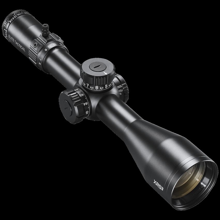
Congratulations on your purchase of the Elite Tactical™ XRS3 Riflescope. Please read this owner’s manual
thoroughly to get the best use out of your riflescope.

        WARNING: NEVER LOOK AT THE SUN THROUGH THE RIFLESCOPE, OR ANY OTHER OPTICAL
        INSTRUMENT, THIS MAY CAUSE PERMANENT EYE DAMAGE.

Elite Tactical XRS3 RIFLESCOPE FEATURES
Elite Tactical™ is constantly at the forefront of quality and innovation. The Elite Tactical XRS3 riflescopes are no exception.
Fully-Multi Coated Optics, ED Prime glass, argon purging, and waterproof construction offer crisp, bright images in every
environment.

All exterior lens surfaces have our EXO Barrier™ coating (in addition to full multi-coatings). EXO Barrier, quite simply,
is the best protective lens coating technology Bushnell has ever developed. Added at the end of the coating process,
EXO Barrier molecularly bonds to the lens and fills the microscopic pores in the glass. The result is an ultra-slick coating
that repels water, oil, fog, dust, and debris; rain, snow, fingerprints, and dirt will not stick. EXO Barrier is built to last: the
bonded coating will not fade with the passage of time or normal wear and tear.

All Elite Tactical XRS3 riflescope models feature:
     • CLARITY - The best resolution and contrast in all lighting conditions.
     • FIRST FOCAL PLANE - Maintains reticle scale at any magnification.
     • HIGH LIGHT TRANSMISSION - Light transmission is increased 2% over XRS II by enhancing the Ultra Wide
         Band Coating system to enable optimum brightness and true color in every lighting condition. Reticle elements
         are etched glass due to the complex pattern and recoil resistance requirements.
     • DURABILITY - Machined from billet aluminum, the primary structural components are rock-solid.
     • REPEATABILITY - Click Value and Tracking are very precise, consistent, and reliable.

The Elite Tactical XRS3 scope covered in this manual include a 34mm tube, G4P reticle, side focus parallax adjustment,
and adjustable or removable PCR ThrowHammer knob, locking windage turret, and non-locking elevation turret with
RevLimiter zero-stop.

KEY ELEMENTS OF A SCOPE
   • Objective Lens: This lens has three functions. First, it permits light to pass into the scope. Second, it determines
      resolution. Generally, larger lens allow more light to enter the scope and resolve details better than smaller ones.
      Finally, it forms an image for the other lenses to magnify to a usable size. The image formed by this lens is upside
      down.
   • Erector System: The erector system serves three functions. Its primary function is to erect the image (that is, flips
      the image right-side-up) and align it to the reticle. During this process, primary magnification of the image takes
      place. The third function is a mechanical one. The erector lenses are housed in a tube constrained by a spherical
      joint at one end, while the other end of the tube is allowed to respond to windage or elevation turret
      adjustments.
   • Reticle: In simple terms, the aiming device around which the scope is built. This element replaces the iron sight
      system of non-scoped rifles.
   • Ocular or Eye Lens: This element provides the secondary and final magnification of the image, and allows for
      reticle focusing independent of the target image focus.

2
PARTS GUIDE

                                                     D-Lok™ Ring (Locking Diopter)
    Fast Focus Eyepiece
                                                              Throw Hammer Knob

    Power Change Ring                                                                  Elevation Turret

                                                                                             Side Focus Adjustment

                 Windage Turret

                                                                                                                          Objective Lens

MOUNTING YOUR SCOPE
Even with its technologically advanced design and features, your new scope will not perform at its best if not properly mounted. One
of the most important contributing factors to the combined accuracy of your scope and rifle is mount selection and the care with
which mounting is done. Dependable mounts that secure your scope to the rifle will reward you with dependability and consistent
accuracy.

Remember, not all scopes are compatible with all mounts on all rifles. If there is any doubt in your mind, you should seek the advice
of your local retailer or gunsmith.

WARNING: A RIFLESCOPE SHOULD NEVER BE USED AS A SUBSTITUTE FOR EITHER A BINOCULAR OR SPOTTING SCOPE. IT
     MAY RESULT IN YOU INADVERTENTLY POINTING THE FIREARM AT SOMETHING YOU DO NOT WISH TO DESTROY.

PRELIMINARY SCOPE ADJUSTMENTS
Before installing the scope, we recommend you calibrate the eyepiece’s focus to your aiming eye’s vision. Refocusing the ocular
distance will sharpen the reticle focus and improve overall optical quality. It will also mitigate eye fatigue/strain when using the scope
over prolonged periods. To refocus, hold the scope about 3 to 4 inches from your eye and point at the open sky or another flatly lit
area such as a monotone painted wall.

Note that the XRS3 has a locking diopter feature. Ensure the diopter is unlocked before making diopter adjustments. First, refer to
D-LOK RING section later in this manual.

Quickly glance into the scope. If the reticle appears blurred at first glance, the diopter requires adjustment. To make the first-
pass, coarse adjustment, again look into the scope, and quickly turn the diopter until the reticle image appears in focus (ignore
the background image). For the final-pass, fine adjustment, remember to take relatively quick glances, as your vision will naturally
compensate for minor out-of-focus conditions with prolonged looks. Quickly glance into the scope and observe the reticle. If the
reticle image is sharp, then you may have gotten lucky, but typically follow-up, fine adjustments are needed. If so, turn the diopter in
a chosen direction by a small amount, then recheck the reticle focus again. If better, continue trials in even smaller amounts to either
side of the new diopter position. If worse, try the other direction. Repeat until the reticle is instantly in focus during a quick glance.

The diopter is now setup for your vision! Typically, only minor adjustments are required over the years. While the collar’s internal
friction should hold it in place with general handling, it is also recommended to reengage the D-Lok diopter lock.

                                                                                                                                             3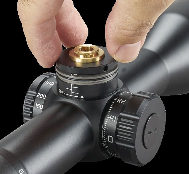
WARNING: BEFORE BEGINNING THE MOUNTING PROCEDURE, BE SURE THE ACTION IS OPEN, THE CLIP OR
        MAGAZINE IS REMOVED, AND THE CHAMBER IS CLEAR. DO NOT ATTEMPT ANY WORK UNTIL YOUR FIREARM HAS
        BEEN CLEARED AND DETERMINED TO BE SAFE.

        WARNING: IF THE SCOPE IS NOT MOUNTED FAR ENOUGH FORWARD, ITS REARWARD MOTION MAY INJURE THE
        SHOOTER WHEN THE RIFLE RECOILS.

While mounting your scope, we recommend that you DO NOT take shortcuts as it may damage either the mounting system or the
scope. Each mounting system will have its own instructions to follow, and it is best to read these first to be ensure you understand
them and have the necessary tools on hand.

We further recommend that you plan to go through the mounting procedure twice. The first time, to be sure everything fits together
and functions properly. On the first run-through, please keep the following in mind:

    •   If applicable, before attaching base/accessory rail, clean the mounting holes in the receiver and the threads of the attaching
        screws with high-concentration IPA (isopropyl alcohol) to free them of oil or grease.
    •   If the mount manufacturer has recommended using a thread adhesive, do not use it on the first mounting trial. Once
        adhesive has been set, it is difficult to demount if anything needs correction and residue will be present that should be
        removed before restarting.
    •   Be sure the mounting screws do not protrude into the receiver.
    •   When using twist-lock style rings, do not use the scope as a lever when installing. The initial resistance to turning may cause
        damage to the scope and is not covered by the warranty. We recommend using a wooden dowel or matching diameter
        metal cylinder to seat the rings.
    •   Be sure the position of the scope does not interfere with the operation of the action.
    •   Be sure there is at least 3mm of clearance between the edges of the rings and any protruding surfaces such as the turret
        housing (saddle), power change ring, and the flare of the objective bell. Note the beginning of fillet transitions for the
        previously mentioned features. Also, be sure there is at least 3mm of clearance between the objective bell and the barrel.
    •   You should test the position the scope for the proper eye relief. The scope rings should be left loose enough so that the
        scope will slide easily. Variable power scopes should be set at the highest magnification when performing this procedure.
        Mount the rifle and look through the scope in your normal shooting position. Unless only going to be used in a bench-rest
        (seated) or prone position (lying down), the modified-prone (leaning over a rest surface while standing or kneeling) position
        is recommended for more versatility.
    •   Test position the rifle for the proper cheek weld several times to ensure that your scope is positioned properly. If the scope
        is too high or low, consider altering the cheek weld riser position, if it is adjustable. Alternatively, different height rings may
        be needed. Be sure adequate clearance is still maintained between the scope and rifle.
    •   When you are satisfied that everything is okay, then add temporary reference markings (masking tape works well for this)
        demount and start again. This time, add scope leveling (anti-cant) considerations while positioning the riflescope, and
        securely fasten all hardware per manufacturer’s instructions. securely fasten all hardware per manufacturer’s instructions.
        Typically, 15 lbf*in is the maximum fastener torque recommended for joints around the scope tube.

PARALLAX
You may have noticed that placing your eye at different positions (i.e. side-to-side OR up-and-down) behind the scope’s eyepiece
causes the reticle to appear to move around to different points on your target. This is called “parallax error” (target and reticle are not
in the same focal plane), and it becomes more noticeable (and more of a problem) the greater the difference between target distance
and side-focus setting. In some cases, parallax will not affect bullet point of impact enough to be of significant concern. If you need to
shoot at a target distance inside of 50 yd, lower magnification settings will be more effective at improving image quality.

D-LOK™ RING (LOCKING DIOPTER)
1. Before any adjustment, ensure D-Lok™ is disengaged by rotating the
   D-Lok™ ring counterclockwise at least 1/2-rotation. (FIG. 1)

2. After the D-Lok™ is disengaged and the Fast-Focus eyepiece ring freely                                                  FAST FOCUS
   rotates, the diopter may be focused to your eye.                                                                        EYEPIECE

3. While looking at a neutral background, such as a clear sky or blank wall,                                               D-LOK™ RING
   adjust the Fast-Focus Eyepiece until the reticle is in focus.
                                                                                                                     FIG. 1

(WARNING: DO NOT LOOK TOWARDS THE SUN!)

4
USING THE SIDE FOCUS
The ET XRS3 model covered in this manual provide an adjustment for parallax compensation (side focus knob), which works by
moving an optical element until the target (based on its distance) appears in the same plane of focus as the reticle. Your ET XRS3
scope can be focused as close as 50 yards. Just line up the estimated distance to your target with the index value or approximate
the distance if between indices, and you will eliminate most of the aiming errors caused by parallax. After setting the side focus,
you can double-check by moving your head around from side to side behind the eyepiece; the point of aim should not shift if the
side focus is correctly set. An alternative method is to look through the scope and turn the side focus knob until the target image, at
whatever range, is sharply focused. Please note the distance markings on the dial are intended as reference points. Exact side focus
adjustments may be needed to achieve a high resolution, parallax-free image. Also note that the rifle and scope must be stationary
when performing parallax error inspections. Any amount of induced movement will directly affect the point-of-aim and provide false
feedback.

USING THE LOCKING WINDAGE TURRET
Your Elite Tactical Riflescope features a T-Lok™ (locking) windage turret, which provides audible and visual adjustment references.
When the turret is pulled into the outward position, rotate in the right or left directions to make appropriate adjustments. Each
increment of the turret provides an audible and tactile “click” that coincides with a visible reference point movement on the turret
knob. Each “click” represents 1/10 MIL. After adjustments, the turret can be pushed back in to prevent movement or left extended
and ready for further adjustments, if preferred.

After adjustments, you can reset the turret to zero by following the steps below:
Note: When resetting the windage turret, ensure the windage turret is in the locked (inboard) position.
Use the included Bushnell multi-tool or a coin to remove the turret cap-screw found on top of the turret knob, do not displace the
o-ring found under the turret cap-screw. Take care not to dislodge the O-Ring on the inner turret body. Also avoid introducing any
contaminants or debris into the exposed turret components.
Remove the turret knob and return it to the inner turret, with the “zero” mark on the knob lining up with the horizontal index line on
the inner turret body.
Return the turret screw to the top of the knob and tighten it down, making sure the turret knob is in the locked position, so the turret
knob does not turn while tightening the screw.

                          FOR WINDAGE TURRET, BE SURE
                            IT IS PULLED OUT TO UNLOCK
                                      BEFORE ADJUSTING.

RESETTING THE ELEVATION TURRET
Rotate the elevation turret knob counterclockwise to move the point-of-aim up or clockwise to move it down. One full revolution of
the elevation dial will move the point of impact 10 MILS at any distance. After zeroing your rifle, you can reset the elevation turret to
zero by following these steps:
    • While holding the elevation turret steady with your free hand, use the included Bushnell multi-tool or a coin to remove the
         turret cap-screw found on top of the turret knob, being careful not to displace the o-ring found under the turret cap-screw.
    • Remove the turret knob and return it to the inner turret with the “zero” mark on the knob lining up with the vertical index line
         on the inner turret body.
    • Return the turret screw to the top of the knob and tighten it down, making sure to steady the turret knob with your free hand,
         so the turret knob does not turn while tightening the screw.

                                                                                                                                            5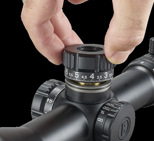
REVLIMITER™ (Zero Stop) INSTRUCTIONS
• Step 1: Obtain a good zero on your rifle. Remove the turret knob cap-screw using the included Bushnell Multi-tool
   or a coin. (FIG. 1)
• Step 2: Remove the turret knob and set it aside (FIG. 2A). Loosen the three set-screws found on the perimeter of the black inner
   locking ring 1½ turns (using 1.5mm hex wrench-provided) (FIG. 2B). These screws are “captured” in the RevLimiter ring so that
   they cannot be completely removed and dropped or lost. Once these set-screws are loosened, the ring should fall down the
   turret shaft.
• Step 3: Turn the RevLimiter disk clockwise until it contacts the fixed pin in the bottom of the turret (FIG. 3A). While holding the
   disk with gentle downward and clockwise pressure, gently tighten the three set screws in the RevLimiter disk to 2 lbf*in (FIG. 3B).
   (Do not overtighten screws. We recommended gripping the short leg of the L-key to reduce leverage). Your zero stop is set.
• Step 4: Re-index the turret knob to zero and return the turret cap-screw to the top of the turret knob and tighten
   (FIG. 4).

         FIG. 1                                   FIG. 2A                                  FIG. 2B

         FIG. 3A                                  FIG. 3B                                  FIG. 4

If you wish to disengage the RevLimiter or you need to change the setting, the sequence is basically the reverse of the above. Secure
the disk in the upward position along the turret shaft to allow the turret to turn freely in the downward direction.

You may also choose to set the RevLimiter to a position that allows you to have POA travel below your absolute zero. A suggestion is to
set it 0.2 to 0.5 MILS below absolute zero so that the turret may be “slipped” quickly and easily to account for ammunition selection or
large atmospheric differences like when traveling to a location with significant elevation change. Just be mindful of turret knob position
before removing and return to the same position. To simplify things, it’s not recommended to turn the inner turret body without the
turret knob installed and secured.

VARIABLE POWER ADJUSTMENTS
Changing the magnification of the ET XRS3 is easily accomplished by grasping the new Throwhammer™ knob, which is fastened to
the power change ring. The throw lever is factory installed , but may be removed with the provided Bushnell Multi-tool. Use the lever
to rotate the power change ring clockwise for higher magnification or counterclockwise for lower magnification. The magnification
setting is identified by noting the number behind the stationary dot on the scope tube.

6
POWER CHANGE RING (PCR) Throwhammer™ ADJUSTMENT
   • The Throwhammer™ knob Is factory installed in the neutral sweep (9 o’clock to 3 o’clock) position.
   • The hardware hex sockets are 7/64 inch. Use the hex driver on the included Bushnell multitool to remove and/or
   reposition the related PCR parts.
   • If the knob is undesired, remove and use the supplied, spare screw to fill in the open tapped hole.
   • A small amount of low-strength, removable thread-locker (e.g. Loctite® 242) may be used.
   • The screws may be torqued to 8-10 lbf * in and the knob to 12-14 lbf * in. CAUTION: Do Not Overtighten

FIRST FOCAL PLANE RETICLE
The ET XRS3 covered by this manual has a reticle located in the first focal plane. Therefore, the reticle will increase in size when
the magnification is increased or vice versa. This feature allows the continued use of the MIL measurement system in the reticle,
regardless of the power setting.

ELITE TACTICAL G4P PRECISION RETICLE
The G4P reticle, developed in conjunction with G.A. Precision,
provides a clean reticle space for fast target acquisition while
the hybrid hash-dot tree provides for intuitive and efficient
holds without using the turrets. The reticle is shown to the right,
but the following pages will provide a more in-depth look.

THE HORIZONTAL CROSSHAIR
The numerically designated MIL markings extend from
the center of the crosshairs outward to the right in 2 MIL
increments on the horizontal crosshair. The numbers were
removed on the left side of the reticle to keep the reticle plane
clean, but the reference points coincide with the markings from
the right side of the crosshair. Measurements from the center
point to the right are as follows: 0.25 MIL, 0.5, 0.75, 1.0, 1.2,
1.5, 2.0, etc.

A carryover feature of the G4P reticle is bold hash marks on the horizontal stadia that provide hold-off marks for shooting at moving
targets. These “mover marks” are located at 1, 1.2, and 1.5 MILS to the left and right of the center of the crosshairs. These are for
typical target speeds at given distances. Use a ballistic solver tool to determine the correct mover hold for your firearm and ammo
combination.

1/2 MIL and 1 MIL markings stop extending at the 8 MIL position. Within the milling bar sections of the reticle, 1 MIL increments are
designated by the longer hash marks, which measure 1.5 MIL in height from top to bottom. Intermediate 0.1 MIL markings are visible
between each 1 MIL marking, are 1 MIL height and extend all the way through the FOV. The 0.1 MIL markings provide you with a
very precise horizontal measurement of your target.

THE VERTICAL CROSSHAIR
Like the horizontal crosshair, the vertical crosshair places the numerically designated MIL markings on only the right side. Once
again, the numerically designated markings are in 2 MIL increments with 0.25 MIL interval hash marks inside of 1 MIL and every 0.5
MIL interval outside of 1 MIL. The 11th MIL measurement down the reticle converts to 0.1 milling bars. The horizontal hashes begin
to elongate for windfall references and floating dots are applied for additional holds without crowding the reticle space to maintain
the relatively clear appearance of the G-series design that familiar users are accustomed to.

                                                                                                                                        7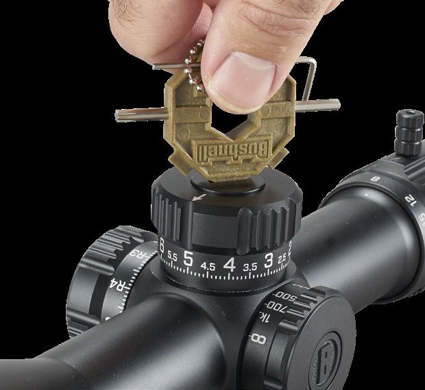
PRELIMINARY SIGHTING-IN
You can save a significant amount of expense and frustration by pre-sighting the scope to the rifle before live-firing. This is also critical
if your berm is small.
Two basic methods can be used for pre-sighting your scope. Method one is to use a Bushnell® Bore Sighter (laser, magnetic or
standard). The use of a Bore Sighter saves time and ammunition and is the system most often used by gunsmiths.
The second method is traditional bore sighting. Rifles are typically sighted-in (aka zeroed) at 100yds, but this is the user’s preference.
The reticle is located in the first focal plane, so the reticle graduations may be used for reference at any magnification setting.

    BORE SIGHTING METHOD
    • Place a target at 100 yards.
    • Remove the bolt from the rifle.
    • Place the rifle on sandbags or shooting rest.
    • Set the scope to approximately 1/3 of the magnification range.
    • Peer through the bore from the receiver end and adjust the rifle’s position to center the target in the                        Fig. A
                                                                                                                            Reticle not in alignment
       bore (Fig. A).
    • Without moving the rifle, look into the scope and note the position of the reticle on the target. Grasp
       the turret and turn it in the appropriate directions indicated by the arrows to center the reticle on the
       bull’s eye (Fig. B). Each “click” or increment on the Adjustment Scale Ring will change the bullet impact
       by the laser engraved value on the top of your scope model’s turret. For reference, 0.1 MIL is
       1cm @ 100m OR 0.36in @ 100yd.
                                                                                                                                      Fig. B
FINAL SIGHTING-IN                                                                                                             Reticle in alignment

         WARNING: SINCE THIS PROCEDURE INVOLVES LIVE FIRE, YOU SHOULD DO THIS AT AN APPROVED RANGE OR
         OTHER SAFE AREA. CHECK BORE FOR OBSTRUCTIONS. AN OBSTRUCTED BORE MAY CAUSE INJURY TO YOU AND
         OTHERS NEARBY. EYE AND EAR PROTECTION IS RECOMMENDED.

From a steady rest position, fire two or three rounds at a 100-yard target. Note the impact of the bullet on the target and adjust the
windage and elevation dials as needed. A shorter distance may be chosen if target size or ammunition is limited. Use this as a coarse
adjustment, then final zeroing distance as the fine adjustment target distance.
To move the point-of-impact, adjust the dial direction to match the desired change. The adjustments on your riflescope model are
marked in MILS (milliradians), and the point of impact at any distance will change by .1 MIL for each click of the windage or elevation
adjustment. One full revolution of turret adjustment=10 MILS.

CARING FOR YOUR RIFLESCOPE
Your scope needs very little maintenance. Exterior metal surfaces should be kept clean. A light dusting with a slightly dampened soft
cloth is enough in most cases.

Your new scope features windage and elevation turrets that are sealed against water and dust ingress, but care must be taken to
avoid introducing contaminants or debris into the turret components while the turret knobs are removed.

We also recommend that lens covers are utilized when the scope is not being used. Lenses should be inspected regularly and
occasionally cleaned depending on contaminant type and amount. Dust, dirt, and fingerprints that collect on the lens surfaces can
degrade image quality. Although lens cleaning is not difficult, it does require care and some patience. Note that it is not necessary to
keep the lens perfectly clean at all times.

For typical dust accumulation, start by using a blow out bulb (using your mouth isn’t ideal due to the moisture that will cause some
particulates to adhere more readily) to dislodge loose debris. A lens brush may also be used. Then use your breath to moisten the
surface and very gently wipe out from center in a spiraling motion.

If the scope has been used outside during a rainstorm and/or has heavy spotting from mud or otherwise, it is recommenced to
introduce a low-pressure water source like from a faucet or bottle of water. If using a garden hose, remove nozzle and reduce flow-
rate.

NOTE: Any cloth must be clean and should be microfiber like the included SPUDS® OR it may be a high quality automotive paint
finish cloth (e.g. $10 per “rag”). Single use lens tissue is also acceptable, but facial tissue is not. Do not use solvents (this includes lens
wipes with IPA). Do not use paper towels or cotton cloths.

8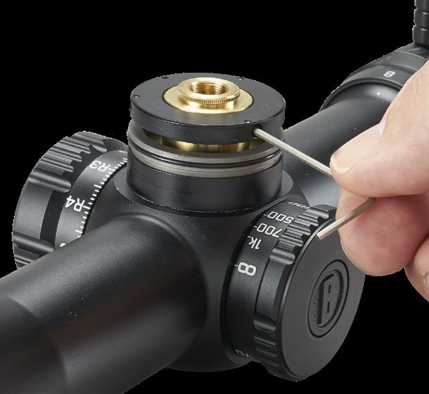
TYP. 0.04
ALL DOTS
G4P Reticle Detail
2X 0.05
OUTSIDE 2 MIL
3X 42.00 B 6X 0.05
LINE WIDTH
A
3X 30.00
2 1
4X 0.12
START OF HASH
FROM CENTER
2X 0.02
INSIDE 2 MILS
0.25
TYP. 1/2 INTERVAL
B
A
8X 0.10
0.50
TYP. HOR INTEGER 2X 0.15
1.20 MILNOTES:
TYP. 0.04 1 - RETICLE IS IN FIRST FOCAL PL
HORIZONTAL ONLY
ALL DOTS 2 - FONT IS CENTURY GOTHIC
B
2X 0.05 3 - FONT HEIGHT IS EQUIVALENT
OUTSIDE 2 MIL 4 - LEADING EDGE OF NUMERA
MILS TO RIGHTOF ADJACENT HO
TYP. 0.10
SPACING
2 1
6X 0.05
LINE WIDTH 2X 0.02 2X 0.175
INSIDE 1 MIL 1.50 MIL HORIZONTAL ONLY
TYP. 1.50
INTEGER BARS
2X 0.050.02
OUTSIDETYP.1THICKNESS
MIL
0.1 INTERVAL
MILLING BARS
3X 0.25
STADIA THICKNESS
STARTS AT 30
TYP. 0.10
SPACING
0.03
TYP. THICKNESS
1 MIL INTERVAL
MILLING BARS
TYP. 1.50
INTEGER BARS
0.02
TYP. 1.00
TYP. THICKNESS
A
0.1 INTERVAL
0.1 INTERVAL
MILLING BARS
MILLING BARS
3X 0.25
STADIA THICKNESS
REMARQUE : L’ÉPAISSEUR DES TRAITS
STARTS AT 30 3 X 0,25 n’est pas présente dans le
réticule G4P de la lunette XRS3.
9
G4P Reticle Detail (cont.)
2 1
0.02
4X 0.50 TYP. VER. HASH
THICKNESS
3.00 0.02
TYP. HOR. HASH THICKNESS
EXCEPT FOR 1.00, 1.20 &
1.50 POSITIONS (BOTH SIDES)
3.00
2.50
2.00
1.50
1.20
1.00
0.75
0.50
0.25
0.50
1.00
1.50
2.00
2.50
3.00
3.50
4.00
0
0.20
TYP. SPACING
2 4 6
0
0.25
0.50
0.75
1.00
1.50
2.00 2
14X 0.25
2X 1.00
2.00 4
2X 3.00
6
2X 4.00
HEIGHT 0.312
8
2X 5.00
0.50
TYP. SPACING
CENTER TO LEAD EDGE
10
0.02
TYP. SECONDARY
0.02 HASH THICKNESS
TYP. SECONDARY
STADIA THICKNESS
2 1
10Technical Specifications
Travel per Revolution (MIL)
Minimum Parallax (Yards)
Windage Travel (MIL)
Eye Relief, Max Mag.
Tube Diameter (mm)
Mag x Obj. Diam.
Elev. Travel (MIL)
Elevation Turrets
Windage Turret
@ 100 Yds (Ft)
Field of View
Weight (oz )
Length (in)
Reticle
SKU
ETXRS3G4 6-36x56 G4P FFP Exposed, Non-Locking w/ Exposed, 29 15 10 34 50 101.6mm 18 - 3 14.8 38.9
RevLimiter™ Zero-Stop Locking
DO YOU NEED TO SEND YOUR SCOPE TO US?
Before returning your scope for service, you should check the following points to make sure the problem is with the scope:
• Check the mounting system and rings for looseness or misalignment.
• Check to be sure the barrel and action are properly bedded and all receiver screws are tight.
• Check to be sure the mounting system allows sufficient clearance between the objective bell and the barrel.
• Check to be sure you are using the same type and weight ammunition that you used for sighting-in.
• Consider moving riflescope over to a different rifle of known function and/or placing an alternative riflescope onto the
primary rifle that is assumed to be non-suspect. The goal is to see if the concern follows the riflescope or remains with
the rifle.
11COVERAGE YOU CAN COUNT ON
All Bushnell products are engineered to deliver to your expectation and manufactured to withstand the rigors of the outdoors
for the lifetime of the product. In the event that our product fails you, we will stand behind it and repair it at no cost to you.
If we can’t repair it then we will replace it with a product of equal or better value. No receipt required and fully transferable.
All Bushnell® products carry a product lifetime warranty against defects in workmanship or materials. Product lifetime is
defined as 30 years for riflescopes, 20 years for binoculars and spotting scopes, 5 years for electro-optics (laser rangefinders,
red dot sights, reflex sights, speed gun radars, night vision, GPS) and electronic components (illuminated reticles) and 2 years
for trail cams. Coverage period start date is determined by proof of purchase or manufacturing date of the product. This
warranty does not cover cosmetic damage; damage caused by failing to properly maintain the product; loss; theft; damage
as a result of unauthorized repair, modification, or disassembly; intentional damage, misuses, or abuse. This Warranty will be
void if the date stamp or other serialization codes have been removed from the Product. We may replace your product with a
product of equal or better physical condition.
To view the full warranty and download the details of the warranty, click this link: https://www.bushnell.com/bu-warranty.html
To submit a repair request or check the status of a repair ticket: https://service.bushnell.com/s/
Alternatively, you can request a copy of the warranty by calling us at 1-800-423-3537 or writing to us at one of the following
addresses:
IN U.S.A. Send To: IN CANADA Send To:
Bushnell Holdings, Inc. Bushnell Holdings, Inc.
Attn.: Repairs Attn.: Repairs
9200 Cody 140 Great Gulf Drive, Unit B
Overland Park, Kansas 66214 Vaughan, Ontario L4K 5W1
Canada
For products purchased outside the United States or Canada, please contact your local dealer for applicable warranty
information.
This warranty gives you specific legal rights and you may also have other rights, which vary from state to state.
We warrant that during the warranty period, with proper use and care, the product will be free from defects in materials and workmanship
and will meet represented performance standards as defined by the warrantor in its sole discretion.
The remedies described herein are your sole and exclusive remedies and our entire liability for any breach of this warranty. Our liability shall
under no circumstances exceed the actual amount paid by you for the defective product, nor shall we under any circumstances be liable for
any consequential, incidental, special or punitive damages or losses, whether direct or indirect.
Some states do not allow the exclusion or limitation of incidental or consequential damages, so the above limitation or exclusion may not
apply to you.
Our responsibility for defective goods is limited to repair or replacement as described in this warranty statement.
©2021 Bushnell Outdoor Products
12FRANÇAIS Félicitations pour l’achat de la lunette de visée Elite Tactical™ XRS3. Merci de lire entièrement ce manuel d’utilisation pour exploiter au mieux la lunette de visée. AVERTISSEMENT : NE JAMAIS REGARDER LE SOLEIL À TRAVERS LA LUNETTE DE VISÉE OU TOUT AUTRE INSTRUMENT OPTIQUE CAR CELA POURRAIT ENTRAÎNER DES LÉSIONS OCULAIRES IRRÉVERSIBLES. CARACTÉRISTIQUES DE LA LUNETTE DE VISÉE Elite Tactical XRS3 Elite Tactical™ est toujours à l’avant-garde en termes de qualité et d’innovation. Les lunettes de visée Elite Tactical XRS3 ne font pas exception à cette règle. Avec un système entièrement revêtu par traitement multicouche, un verre de qualité à faible dispersion, purgé à l’argon, et une construction étanche, cet instrument offre des images nettes et claires dans tout type d’environnement. Toutes les surfaces externes sont recouvertes de notre nouveau revêtement EXO Barrier™ (outre l’application intégrale de revêtements multicouche). EXO Barrier est tout simplement la meilleure technologie de revêtement de protection des lentilles jamais développée par Bushnell. Ajouté à la fin du procédé de revêtement, EXO Barrier se lie moléculairement à la lentille et remplit les pores microscopiques dans le verre. Il en résulte un revêtement ultra-lisse imperméable à l’eau, l’huile, au brouillard, à la poussière, aux débris. Sa surface n’offre aucune adhérence à la pluie, à la neige, aux empreintes digitales et à la saleté. En outre, EXO Barrier est conçu pour durer : c’est un revêtement adhérent qui ne s’estompe pas avec le temps ou suite à l’usure naturelle normale. Tous les modèles de lunette de visée Elite Tactical XRS3 offrent les fonctionnalités suivantes : • CLARTÉ – La meilleure résolution et un contraste optimal en toutes conditions de luminosité. • PREMIER PLAN DE MISE AU POINT – L’échelle du réticule est maintenue indépendamment du grossissement. • TRANSMISSION LUMINEUSE ÉLEVÉE – La transmission lumineuse augmente de 2 % avec DMR II Pro grâce à l’amélioration du système de revêtement à bande extra large, qui offre une luminosité optimale et un rendu des couleurs exact en toutes conditions de luminosité. Les éléments du réticule sont en verre gravé en raison du motif complexe et des exigences de résistance au recul. • DURABILITÉ – Fabriquée à partir d’aluminium, les composants structurels principaux sont extrêmement résistants. • RÉPÉTABILITÉ – La valeur du déclic et le suivi sont très précis, conformes et fiables. La lunette de visée Elite Tactical XRS3 décrite par ce manuel se rapporte à un tube de 34 mm, à un réticule G4P, à un ajustement latéral de parallaxe de la mise au point, à une tourelle de blocage de la dérive par mollette PCR « ThrowHammer » ajustable ou amovible et à une tourelle d’élévation non-bloquante avec RevLimiter « zéro stop ». ÉLÉMENTS PRINCIPAUX D’UNE LUNETTE DE VISÉE • Lentille de l’objectif : La lentille de l’objectif a trois fonctions. D’abord, elle permet à la lumière de passer dans la lunette. Ensuite, elle détermine la résolution. Généralement, plus la lentille est grande, plus elle laisse pénétrer de lumière dans la lunette, permettant un meilleur discernement des détails. Enfin, elle forme une image que les autres lentilles grossissent à une taille utilisable. L’image formée par cette lentille est à l’envers. • Système érecteur : Le système érecteur remplit trois fonctions. Sa fonction principale consiste à ériger l’image (c’est- à-dire, à retourner l’image dans le bon sens) et à l’aligner sur le réticule. Pendant ce processus a lieu le grossissement principal de l’image. La troisième fonction est mécanique. Les lentilles érectrices sont logées dans un tube limité par un joint sphérique à une extrémité. L’autre extrémité du tube peut répondre aux ajustements de la tourelle de dérive ou d’élévation. • Réticule : Le réticule est tout simplement le dispositif de visée autour duquel est construite la lunette. Cet élément remplace le système de vue en fer des fusils sans lunette. • Oculaire ou œilleton : Cet élément fournit le grossissement secondaire et final de l’image et permet la mise au point du réticule indépendamment de la mise au point de l’image cible.
GUIDE DES PIÈCES
                                                          Bague D-Lok™ (Verrouillage du dioptre)
       Oculaire à mise au
                                                                  Mollette « Throw Hammer »
             point rapide

                                                                                             Tourelle d’élévation
      Bague de réglage du
           grossissement
                                                                                                   Ajustement de la mise
                                                                                                   au point latérale
                 Tourelle de dérive

                                                                                                                                  Objectif

INSTALLATION DE LA LUNETTE
En dépit de sa conception et de ses fonctionnalités technologiquement avancées, sans un montage correct, cette lunette de visée n’offrira pas
une utilisation optimale. L’un des facteurs importants les plus déterminants pour obtenir une précision combinée de la lunette et du fusil est
le choix du support et le soin apporté au montage. Des supports solides permettant une fixation sécurisée de la lunette sur le fusil offrent une
extrême fiabilité et une précision rigoureuse.

Point important : toutes les lunettes ne sont pas compatibles avec tous les supports sur tous les fusils. En cas de doute, demander conseil à un
revendeur ou armurier local.

             AVERTISSEMENT : NE PAS UTILISER UNE LUNETTE DE VISÉE EN REMPLACEMENT DE JUMELLES OU D’UN TÉLESCOPE
             D’OBSERVATION. CELA POURRAIT, PAR MÉGARDE, ENTRAÎNER UN POINTAGE DE L’ARME À FEU VERS UN OBJET QUE
             L’ON NE SOUHAITE PAS DÉTRUIRE.

RÉGLAGES PRÉLIMINAIRES DE LA LUNETTE DE VISÉE
Avant d’installer la lunette, nous recommandons de calibrer la mise au point de l’oculaire à la vision de l’œil de visée de l’utilisateur. Remettre
au point la distance oculaire augmentera la netteté de la mise au point du réticule et améliorera la qualité optique globale. Cette mise au point
atténuera également la fatigue/contrainte oculaire lors d’une utilisation prolongée de la lunette. Pour effectuer une remise au point, maintenir
la lunette à environ 3 à 4 pouces de l’œil et pointer vers le ciel ouvert ou vers une autre zone présentant un éclairage plat, par exemple une
peinture murale monotone.

Remarque : la lunette XRS3 est équipée d’un dispositif de blocage du dioptre. Toujours s’assurer que le dioptre est déverrouillé avant
d’effectuer tout ajustement à l’oculaire. D’abord, se référer à la section BAGUE D-LOK plus loin dans ce manuel.

Jeter un coup d’œil rapide dans la lunette. Si le réticule apparaît flou au premier coup d’œil, le dioptre doit être mis au point. Pour effectuer le
premier réglage grossier, regarder à nouveau dans la lentille et tourner rapidement le dioptre jusqu’à ce que l’image sur le réticule apparaisse
nette (ignorer l’image de fond). Ne pas oublier de jeter des coups d’œil rapides pour le réglage final et ajusté, car l’œil compense naturellement
les conditions légèrement floues par des regards prolongés. Regarder à nouveau à travers la lentille et observer le réticule. Une image nette du
réticule à ce stade est probablement un coup de chance. En général, des réglages complémentaires plus précis s’avèrent nécessaires. Si c’est
le cas, tourner légèrement la bague de réglage dioptrique dans une direction choisie, puis revérifier la mise au point du réticule. Si les résultats
sont meilleurs, répéter les essais en tournant encore plus légèrement d’un côté ou de l’autre à partir de la nouvelle position du dioptre. Si les
résultats obtenus sont mauvais, essayer dans l’autre direction. Répéter cette procédure jusqu’à ce que le réticule soit net lors de l’observation.

La dioptrie est maintenant adaptée à la vision de l’utilisateur ! En général, seuls quelques légers réglages s’avèreront nécessaire au fil des ans.
Cependant, si la friction interne de la bague suffit à la maintenir en place lors d’une manipulation normale, il est recommandé de réarmer le
verrouillage de l’oculaire D-Lok.
AVERTISSEMENT : AVANT DE COMMENCER LA PROCÉDURE DE MONTAGE, VÉRIFIER QUE LE MÉCANISME
EST OUVERT, LE CLIP OU LE CHARGEUR RETIRÉ ET LA CHAMBRE VIDE. NE PAS INTERVENIR PAS AVANT
D’AVOIR VÉRIFIÉ QUE L’ARME EST VIDE ET SÛRE.
AVERTISSEMENT : SI LA LUNETTE N’EST PAS MONTÉE SUFFISAMMENT EN AVANT, SON MOUVEMENT VERS
L’ARRIÈRE PEUT BLESSER LE TIREUR AU MOMENT DU RECUL DE L’ARME.
Lors de l’installation de la lunette, nous recommandons de ne PAS sauter d’étapes, sous peine d’endommager le système de montage ou la
lunette. Chaque système de montage comporte ses propres instructions qu’il convient de suivre et il est préférable de commencer par lire les
instructions pour s’assurer de les comprendre et de disposer des outils nécessaires à portée de main.
Nous recommandons en outre d’effectuer deux fois la procédure de montage. La première fois, pour s’assurer que toutes les pièces sont bien
installées et fonctionnent correctement. Lors de la première procédure de montage, garder à l’esprit les points suivants :
• Le cas échéant, avant de fixer la base/le rail de l’accessoire, nettoyer les trous de montage dans le récepteur et les filets des vis de fixation
avec de l’alcool isopropylique à forte concentration pour retirer l’huile ou la graisse éventuellement présente.
• Si le fabricant du support recommande une colle à filetage, ne pas l’utiliser lors du premier essai de montage. Une fois que la colle prend,
il est difficile de démonter l’ensemble si une pièce doit être corrigée. Tout résidu doit être enlevé avant de recommencer l’opération.
• Vérifier que les vis de montage ne dépassent pas dans le récepteur.
• Si des supports à verrouillage rotatif sont utilisés, ne pas utiliser la lunette comme levier pour l’installer. La résistance initiale à la rotation
peut endommager la lunette, ce qui n’est pas couvert par la garantie. En guise d’alternative, nous recommandons l’utilisation d’une cheville
en bois ou d’un cylindre métallique de diamètre correspondant pour installer les bagues.
• Vérifier que la position de la lunette n’interfère pas avec le fonctionnement du mécanisme
• S’assurer de la présence d’un jeu d’au moins 3 mm entre les bords des bagues et les surfaces en saillie, telles que le logement de la
tourelle (selle), la bague de sélection de portée et l’évasement du logement de l’objectif. Noter le début des crans de transition pour les
fonctionnalités mentionnées précédemment. S’assurer également qu’il y ait au moins 3 mm de jeu entre le logement de l’objectif et le canon.
• Tester la position de la lunette pour obtenir un dégagement oculaire adéquat. Les colliers de la lunette doivent être suffisamment lâches
pour permettre un coulissement aisé de la lunette. Dans le cadre de cette procédure, les lunettes à grossissement variable doivent être
réglées sur le grossissement maximal. Monter le fusil, puis regarder à travers la lunette en position de tir normale. À moins que la lunette ne
soit exclusivement utilisée en position de repos stable (assise) ou couchée (allongée), la position couchée-modifiée (debout ou à genoux, avec
appui contre une surface stable) est recommandée pour plus de polyvalence.
• Tester plusieurs fois la position du fusil pour déterminer le bon calage de la crosse contre la joue et afin de s’assurer de la bonne position
de la lunette. Si la lunette est trop haute ou trop basse, modifier éventuellement le calage crosse/joue si possible. Sinon, utiliser des colliers
de différentes hauteurs. S’assurer qu’un dégagement suffisant est présent entre la lunette et le fusil.
• Si le montage est satisfaisant et que tout est réglé, ajouter des points de repère temporaires (avec de l’adhésif par exemple), procéder au
démontage et recommencer. Cette fois, tenir compte du nivelage de la lunette (anti-dévers) lors de son positionnement et fixer solidement
tout le matériel conformément aux instructions du fabricant. Fixer solidement tout le matériel conformément aux instructions du fabricant.
Généralement, 15 livres-force pouce est le couple maximum de serrage recommandé pour les colliers du tube de la lunette.
PARALLAXE
La position du réticule sur la cible varie en fonction de la position de l’œil derrière la lunette (côte à côte ou haut et bas). Ce phénomène
est appelé « erreur de parallaxe » (la cible et le réticule ne se trouvent pas sur le même plan de mise au point) et devient plus visible (et
donc plus problématique) si la différence entre la distance de la cible et le paramètre de mise au point latérale est élevée. Dans certains
cas, la parallaxe n’aura pas suffisamment d’effet sur le point d’impact de la balle pour être une source de préoccupation significative.
Cependant, si l’on doit tirer à une distance de cible à moins de 25 yards, des paramètres de grossissement plus faibles amélioreront la
qualité d’image.
BAGUE D-LOK™ (VERROUILLAGE DU DIOPTRE)
Avant d’effectuer le moindre réglage, s’assurer que D-Lok™ est désarmé en
faisant pivoter la bague D-Lok™ dans le sens contraire des aiguilles d’une
montre d’au moins 1/2 rotation. (FIG. 1)
Oculaire à mise
Après avoir désarmé le D-Lok™, l’oculaire à mise au point rapide tourne au point rapide
librement, et le dioptre peut être adapté à l’œil de l’utilisateur.
Bague D-Lok™
Ajuster l’oculaire à mise au point rapide jusqu’à ce que le réticule soit net lors (Verrouillage du
de l’observation d’un fond neutre, comme un ciel dégagé ou un mur nu. dioptre)
FIG. 1
(ATTENTION : NE PAS REGARDER LE SOLEIL!)UTILISATION DE LA MISE AU POINT LATÉRALE
Le modèle ET XRS3 décrit dans ce manuel comporte un réglage permettant de corriger la parallaxe (molette de mise au point latérale), qui
fonctionne en déplaçant un élément optique jusqu’à ce que la cible (en fonction de sa distance) apparaisse dans le même plan focal que
le réticule. La lunette XRS3 est réglée en usine pour une mise au point à 50 yards. Aligner simplement la distance estimée à la cible sur
une valeur d’indice ou estimer la distance entre les indices. Ainsi, la plupart des erreurs de visée causées par la parallaxe seront éliminées.
Revérifier le réglage de l’objectif en bougeant la tête d’un côté à l’autre derrière la lunette : si la mise au point latérale est bonne, le
point de visée ne doit pas bouger. Il est également possible d’effectuer un réglage à n’importe quelle distance, en regardant à travers la
lunette et en tournant la mollette de mise au point latérale jusqu’à ce que la cible devienne nette. Remarque : les marques de distances
sur le cadran constituent des points de repère. Des réglages latéraux précis peuvent s’avérer nécessaires pour obtenir une image haute
résolution sans parallaxe. Il convient également de noter que le fusil et la lunette doivent être immobiles lorsque sont effectuées des
inspections d’erreurs de parallaxe. Tout mouvement induit affectera directement le point de visée et génèrera un relevé incorrect.
UTILISATION DE LA TOURELLE DE DÉRIVE BLOQUANTE
La lunette Elite Tactical est dotée d’une tourelle de dérive (bloquante) T-Lok™, offrant des repères de réglage acoustiques et visuels.
Une fois la tourelle tirée en position extérieure, la faire pivoter vers la droite ou vers la gauche pour effectuer les réglages appropriés.
Chaque incrément de la tourelle produit un « clic » sonore et tactile qui coïncide avec un mouvement de référence visible sur la mollette
de la tourelle. Chaque « clic » représente 1/10 de MIL. Après réglage, la tourelle peut être repoussée vers l’intérieur pour empêcher tout
mouvement ou étendue vers la gauche, prête pour de nouveaux réglages, au choix.
Après réglage, la tourelle peut être zérotée en suivant les étapes ci-dessous :
Remarque : Lors du zérotage de la tourelle de dérive, s’assurer qu’elle se trouve en position bloquée (vers l’intérieur).
Utiliser l’outil multifonction Bushnell inclus ou une pièce de monnaie pour retirer la vis de blocage située au-dessus de la mollette de la
tourelle. Ne pas déplacer le joint torique inséré sous la vis de blocage de la tourelle. Veiller à ne pas déloger le joint torique sur le corps
intérieur de la tourelle. En outre, éviter également de faire pénétrer des contaminants ou débris dans les composants exposés de la
tourelle.
Retirer la mollette de la tourelle et la tourner vers l’intérieur, afin d’aligner la marque « zéro » sur la ligne de repère horizontale sur le corps
intérieur de la tourelle.
Replacer la vis sur la mollette de la tourelle et serrer en veillant à ce que la mollette de la tourelle soit en position verrouillée, afin d’éviter
qu’elle ne tourne pendant le serrage de la vis.
POUR LA TOURELLE DE DÉRIVE, VÉRIFIER
QU’ELLE EST TIRÉE VERS L’EXTÉRIEUR
AVANT D’EFFECTUER TOUT RÉGLAGE.
ZÉROTAGE DE LA TOURELLE D’ÉLÉVATION
Tourner la mollette de la tourelle d’élévation dans le sens contraire des aiguilles d’une montre pour déplacer le point de visée vers le haut
ou dans le sens des aiguilles d’une montre pour le déplacer vers le bas. Un tour complet du cadran d’élévation déplace le point d’impact
de 10 MIL quelle que soit la distance. Après avoir zéroté le fusil, procéder au zérotage de la tourelle d’élévation en suivant les étapes
suivantes :
• Tout en maintenant fermement la tourelle d’élévation avec une main libre, utiliser l’outil multifonctions Bushnell inclus ou une pièce
de monnaie pour retirer la vis de blocage située au-dessus de la mollette de la tourelle. Ne pas déplacer le joint torique inséré sous
la vis de blocage de la tourelle.
• Retirer la mollette de la tourelle et la tourner vers l’intérieur, afin d’aligner la marque « zéro » sur la ligne de repère verticale sur le
corps intérieur de la tourelle.
• Replacer la vis sur la mollette de la tourelle et serrer en veillant à maintenir fermement la mollette de la tourelle avec une main libre,
afin d’éviter qu’elle ne tourne pendant le serrage de la vis.INSTRUCTIONS REVLIMITER™ (zéro stop)
• Étape 1 : Obtenir un bon zérotage du fusil. Retirer la vis de blocage de la mollette de la tourelle à l’aide de l’outil multifonctions
Bushnell ou d’une pièce de monnaie. (FIG. 1)
• Étape 2 : Retirer la mollette de la tourelle et la mettre de côté (FIG. 2A). Desserrer les trois vis de réglage autour de la bague de
serrage intérieure de 1 tour ½ (utiliser la clé Allen de 1,5 mm fournie) (FIG. 2B). Ces vis sont « capturées » dans la bague RevLimiter de
sorte qu’il est impossible de les retirer complètement, de les faire tomber ou de les perdre. Une fois ces vis de réglage desserrées, la
bague est censée tomber au bas de l’axe de la tourelle.
• Étape 3 : Tourner le disque RevLimiter dans le sens des aiguilles d’une montre jusqu’à ce qu’il entre en contact avec la goupille fixe au
bas de la tourelle (FIG. 3A). Tout en maintenant le disque en exerçant une légère pression de haut en bas et dans le sens des aiguilles
d’une montre, serrer doucement les trois vis de réglage dans le disque RevLimiter à 2 livres-force pouce (FIG. 3B). (Ne pas serrer
excessivement les vis. Nous recommandons d’utiliser la partie courte de la clé Allen afin de réduire l’effet de levier). Le zéro stop est
réglé.
• Étape 4 : Replacer la mollette de la tourelle sur zéro et réinsérer la vis de blocage sur celle-ci, puis serrer (FIG. 4).
FIG. 1 FIG. 2A FIG. 2B
FIG. 3A FIG. 3B FIG. 4
Si l’on souhaite désactiver le RevLimiter ou modifier le réglage, les étapes à suivre sont l’inverse des précédentes. D’abord,
sécuriser le disque en position haute le long de l’axe de la tourelle pour permettre à celle-ci de tourner librement vers le bas.
Il est également possible de configurer le RevLimiter dans une position permettant au point de visée de passer sous
le zéro absolu de l’utilisateur. Nous suggérons de le configurer entre 0,2 et 0,5 MIL sous le zéro absolu de sorte que la
tourelle puisse « glisser » rapidement et facilement afin de tenir compte de la sélection de munitions ou de différences
atmosphériques élevées, par exemple lors d’un déplacement dans un lieu présentant un changement d’altitude significatif.
Veiller à bien noter la position de la mollette de la tourelle avant de l’enlever, afin de pouvoir la replacer dans la même
position. Il n’est pas recommandé de tourner le corps intérieur de la tourelle si la mollette de la tourelle n’est pas installée et
fixée.
RÉGLAGE DU GROSSISSEMENT
Le réglage du grossissement sur la lunette ET XRS3 est facilité par le nouveau levier « Throwhammer™ », placé sur la bague
de sélection du grossissement. Ce levier est installé en usine mais peut être ôté à l’aide de l’outil multifonctions Bushnell
fourni. Utiliser le levier pour faire pivoter la bague de sélection du grossissement dans le sens des aiguilles d’une montre
pour augmenter le grossissement ou dans le sens contraire des aiguilles d’une montre pour le réduire. Le réglage du
grossissement est identifié par un chiffre mentionné derrière le point stationnaire sur le corps de la lunette.BAGUE DE SÉLECTION DU GROSSISSEMENT ET RÉGLAGE THROWHAMMER™
• Le levier « Throwhammer™ » est installé en usine en position champ neutre (de 9 heures à 3 heures).
• La dimension de clé Allen à utiliser est 7/64 pouces. Utiliser la clé Allen présente sur l’outil multifonctions Bushnell fourni pour
ôter et repositionner les pièces de la bague de sélection du grossissement.
• Si l’on souhaite retirer le levier, insérer la vis de rechange fournie pour combler le trou taraudé.
• Il est possible d’utiliser une petite quantité de colle à filetage de faible force (par exemple, Loctite® 242).
• Les vis peuvent être serrées à 8-10 livres-force pouce et la mollette à 12-14 livres-force pouce.
ATTENTION : Ne pas trop serrer
RÉTICULE AU PREMIER PLAN DE MISE AU POINT
La lunette ET XRS3 décrite dans ce manuel possède un réticule situé dans le premier plan de mise au point. Par conséquent, la taille du
réticule augmente avec l’augmentation du grossissement et vice-
versa. Ce dispositif permet l’utilisation continue du système de
mesure MIL dans le réticule, indépendamment du réglage de
grossissement.
RÉTICULE DE PRÉCISION ELITE TACTICAL G4P
Le réticule G4P, développé avec la collaboration de G.A. Precision,
est net et espacé pour un repérage rapide de la cible. À l’inverse,
l’axe hybride traits-points garantit une tenue intuitive et efficace
sans utiliser les tourelles. Le réticule s’affiche sur la droite, mais les
pages suivantes contiennent des explications plus détaillées.
LA MIRE HORIZONTALE
Les chiffres-repère exprimés en MIL partent du centre de la mire
vers la droite et sont exprimés en incréments de 2 MIL sur la mire
horizontale. Les chiffres sont absents sur le côté gauche du réticule
pour conserver la netteté du plan du réticule, mais les points de
repère coïncident avec les inscriptions présentes sur le côté droit
de la mire. Les mesures à partir du point central vers la droite sont les suivantes : 0,25 MIL, 0,5, 0,75, 1,0, 1,2, 1,5, 2,0, etc.
La fonction de report du réticule G4P apparaît sous la forme de repères sur les traits horizontaux et constituent des repères de mise à
distance pour le tir sur des cibles mouvantes. Ces « marques de mouvement » se situent à 1, 1,2 et 1,5 MIL vers la gauche et vers la droite
à partir du centre de la mire. Elles sont utilisées pour des vitesses de cible classiques à des distances données. Utiliser un instrument de
mesure balistique pour déterminer la tenue correcte du fusil et munitions.
Les intervalles à ½ MIL et à 1 MIL s’interrompent à la position 8 MIL. Dans les sections à tirets du réticule, les incréments de 1 MIL sont
indiqués par des repères plus longs, qui mesurent 1,5 MIL de haut en bas. Les intervalles intermédiaires à 0,1 MIL sont visibles entre la
marque 1 MIL, hauteur 1 MIL et vont jusqu’au champ de vision. Les intervalles à 0,1 MIL fournissent un repérage horizontal très précis de
la cible. Par exemple, à 30 MIL du centre, une barre fixe de repérage rapide fait 0,25 MIL de haut. Elle n’est visible que si les réglages de
grossissement sont bas.
LA MIRE VERTICALE
Sur la mire verticale, les chiffres-repère exprimés en MIL s’affichent uniquement du côté droit, comme pour la mire horizontale. Encore une
fois, les chiffres repère sont représentés par des incréments de 2 MIL avec des marques d’intervalle de 0,25 MIL sous 1 MIL et tous les 0,5
MIL d’intervalle au-dessus de 1 MIL. La 11e mesure MIL au bas de la mire passe à des crans de 0,1 et la barre de rep. Le prolongement des
traits horizontaux fournit des références de dérive et l’insertion de points flottants évite la surcharge de l’espace du réticule pour conserver
l’apparence relativement claire du design de la gamme G bien connue des utilisateurs fréquents.You can also read