Presents EMC Design Considerations in DC-DC Converters for Automotive Application
←
→
Page content transcription
If your browser does not render page correctly, please read the page content below
Presents

 EMC Design Considerations in DC-DC
 Converters for Automotive Application
Dr. Min Zhang
February, 2021
Visit: www.mach1design.co.uk
Email: info@mach1design.co.uk
This presentation outlines
This Presentation outlines:
 1. DC-DC converters in the automotive industry
 2. DC-DC design challenges from an EMC perspective
 3. DC-DC converters EMC testing & trouble shooting

This Presentation is one of a series that include:
 EMC in Electric Drive Unit - New Challenges for the Automotive Sector
 Grounding & shielding technique for EV application
 And More
 Page 1 of 96 Dr Min Zhang - February 2021
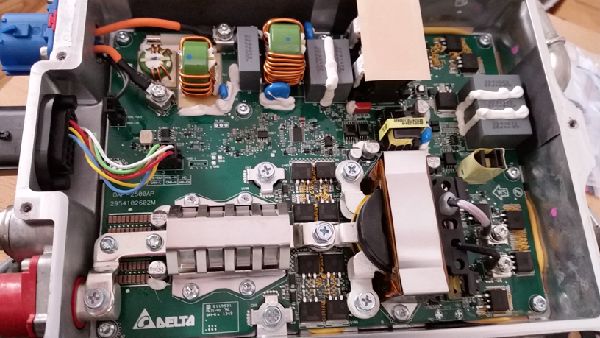
The key element in managing power
In electric vehicle application, DC-DC converters have now replaced
alternators in internal combustion engine vehicles.

 1. Key component in providing low voltage power
 2. Functional safety critical
 3. Safety critical
 4. Supply instantaneous huge current demand
A Tesla DC-DC module made by Delta Electronics

 Page 2 of 96 Dr Min Zhang - February 2021
Bridging HV and LV systems in EVs
 Converting high voltage power to low voltage power

 H Power low 48 &/ 12V
 400 - 800 V
 DC DC
 LV Battery

 Battery Pack M M
 Loads All LV loads
 Electric Drive Unit HV compressor motor

 Page 3 of 96 Dr Min Zhang - February 2021
V

 -
 f
Also common in hybrids and PHEVs

 Commonly seen in systems where both 12V and 48V power systems
 co-exist.
 Power low

 12V DC DC 48V

 Such as chassis
 control, electric
 Alternator M
 12V Battery Loads Super caps power steering or Loads
 braking system

 Page 4 of 96 Dr Min Zhang - February 2021
-
 f
Simpli ed schematics of HV LV DC-DC

 HV+

 Y-Caps

 DC Link 12V

 Chassis Ref

 HV-
 HV- Bus 0V Ref

 Multi-stage Input Filter Boost Converter Phase Shift Full Bridge Sync Recti er Output Filter

 Simpli ed schematics of phase shift full bridge converter

 Page 5 of 96 Dr Min Zhang - February 2021
fi
 fi
 fi
Simpli ed schematics of LV DC-DC

 48V 12V

 0V Ref

 Filter Stage Power Conversion Stage Filter Stage

 Simpli ed schematics of a bi-directional buck boost converter

 Page 6 of 96 Dr Min Zhang - February 2021
fi
 fi
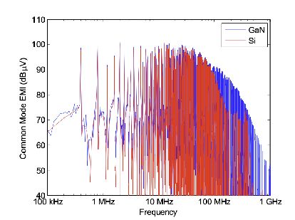
State-of-the-art design and new trend
The end game is to achieve the highest power density, which means:
 . High switching frequency - so as to keep passive components small

⚡. Fast switching speed - to minimise loss, hence improve thermal. GaN and Sic MOSFETs
are the design of choices
 . Advanced thermal materials and design - new materials together with system thermal
solution
 . Enhanced electromagnetic design - to reduce eddy current loss, avoid using large and bulky
EMC lter components

 . State-of-the-art PCB design - to achieve small size and good EMC performance

 . And to keep the whole module at low cost - this really should be put as rule NO.1 !

 Page 7 of 96 Dr Min Zhang - February 2021
fi
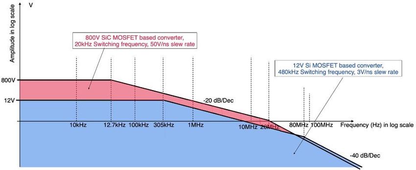
DC-DC EMC design challenges

⚠. A high voltage challenge . Problem of being fast

 Common mode current ICM=CstraydV/dt

 Available Y-Class cap CY=2E/V2

 400V 800V 1200V EV HV design trend

 Page 8 of 96 Dr Min Zhang - February 2021

DC-DC EMC design challenges - Continued

In fact, all the electronics design requirements are EMC design
constraints in one way or another! Why?
. High switching frequency means more EMI energy
. Fast switching speed indicates it hurts more (noise wise) every time a switching event occurs
. Thermal requirement will require high switching frequency and fast switching speed (to
minimise switching loss), but as the points made above, it is bad for EMC. Thermal paste also
means no direct electric connection.

. Most of the time, electromagnetic design only focuses on power conversion function without
taking care of the leakage ux.

. And you want to apply 6 layer or 12 layer PCB? No no no, that’s way too expensive!

 Page 9 of 96 Dr Min Zhang - February 2021
 fl
DC-DC EMC design challenges - Continued

On top of those challenges, we have
. More stringent EMC requirements - worldwide

. Safety critical requirement and functional safety requirement

. Communication circuit evolution, used to be CAN, now CAN FD, Flexray, automotive
ethernet in future

. New EMC requirements such as HV/LV attenuation, HV transient, etc

 Page 10 of 96 Dr Min Zhang - February 2021
Switching frequency and speed e ect

When doubling the switching frequency, generally we end up being 6dB worse
 6 dB

 0 dB

 f

When doubling the switching speed, we get at least another 3dB increase in high frequency of EMI
spectrum

 Page 11 of 96 Dr Min Zhang - February 2021
 ff
On chassis, 0V, ground, or earth?

Have you found the ‘quiet ground’ yet? - It is a joke! There’s no such
thing as a ‘quiet ground’!
 Instead, we often see:

 . Too many di erent symbols on one schematic

 . Ground plane is not a plane (often with track or gap on the plane)

 . Connection between 0V reference and chassis reference is high
 impedance
 . Connection between the ‘analogue ground’ and ‘digital ground’ is
 a think track

 Page 12 of 96 Dr Min Zhang - February 2021
 ff
A commonly seen issue

A commonly seen issue is a high impedance connection between di erent references. This high
impedance path could be a poor electrical connection, or lack of gasket, or oxidised metal structure,
which means noise voltage developed cross it will help drive emissions.
 KL 30

 0V + -

 + + -
 Chassis Reference
 Metal Enclosure -
 The true ‘quiet’ reference in the system, in which all
 signals are referenced to

 Page 13 of 96 Dr Min Zhang - February 2021

 ff
How e ective is your lter?

Most of the lters are somehow ine ective due to various reasons.
. Inductor is by passed by nearby conductors (could easily bypassed by a ground plane, for
instance)
. Inductor is the wrong type (for instance, too many turns, use power conversion type in lter
type application, etc)
. L-C resonance (you might put a damping resistor in there, but is it in the right place?)

. Filter location is wrong (EMI lter should be placed near the connector not the power stage)

. Too many capacitors make lter performance worse (yes, surprising facts!)

. Should I put ground plane under the inductor or not? (A million dollar question!)

 Page 14 of 96 Dr Min Zhang - February 2021
 ff
 fi
 fi
 fi
 fi
 ff
 fi
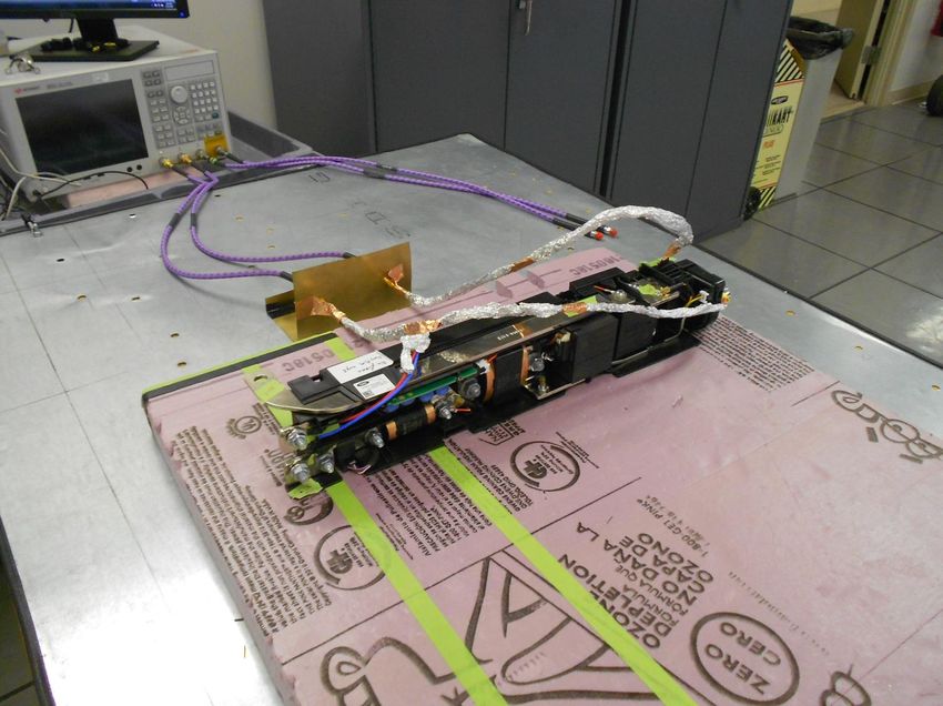
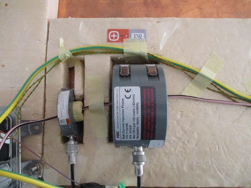
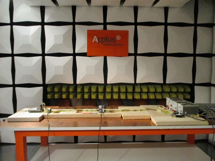
EMC testing and trouble shooting File Number: DRAFT REPORT
 Page Number 232/462

 RI 112 – RF Immunity (BCI)

 Temperature: 22.2 – 23.1 ºC
 Test date: 17/11/2020 – 24/11/2020 Humidity: 47.3 – 53.1 %
 Test area: SAC-4 Atm. pressure: 1025.5 - 1027.1 mbar

 Test Setup
e order EMI filter using two inductors performWhat
 better
 we found is now that usually force order EMI filter using two inductors perform better

 Generally speaking, if you failed conductive emission test, chances are
size and the specialty height of these components
 because you can reduce a component size and the specialty height of these components
now. So for less area, less volume, less money, you and get the same filter effect now. So for less area, less volume, less money, you
 basically

 that you will fail radiated emission test, together with radiated immunity
son that it's physically a lot smaller. get better filter effect for the simple reason that it's physically a lot smaller.

 tests.
 Fig. 361: Test setup – RI 112, BCI

 Fig. 362: Test setup – RI 112, Bulk injection probe at 150 mm position. DBCI test setup

 Conducted emission Radiated emission Bulk current injection HV/LV coupling

 Page 15 of 96 Dr Min Zhang - February 2021
Contact us for the full-length detailed presentation

 Design Review and Diagnosis
 Compliance
 Consulting
 Training

 Visit: www.mach1design.co.uk
 Email: info@mach1design.co.uk

Page 16 of 96 Dr Min Zhang - February 2021
You can also read