Pressure Points - Munich Re
←
→
Page content transcription
If your browser does not render page correctly, please read the page content below
Pressure Points
Table of contents “Let’s Get Digital”
“Let’s Get Digital”.............................. 1
Code use of digital pressure gauges for hydrostatic testing
History and Status of Grade 91 Author: Paul Coco, Senior Engineer
Creep-Strength-Enhanced Date: February 23, 2021
Ferritic Steel....................................... 3
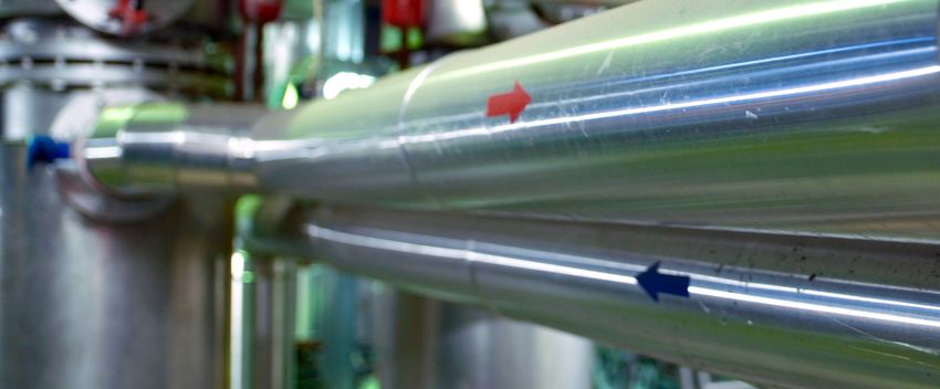
In the last 20 years, the use of digital pressure gauges for industrial applications
Ask the Engineer............................... 5 has increased due to advantages in durability, calibration, customization,
reliability and readability over the traditional analog gauges. Digital pressure
2021 Technical Training and gauges are devices that convert applied pressure into signals with readouts
Marketing Events.............................. 6 displayed numerically, while analog gauges use a dial. Although analog and
digital pressure gauges fulfill the same function, each apply different
technologies and are used in various applications.
Limitations associated with both analog and digital pressure gauges dictate a
prescribed use for their application. Understanding these limitations across
industry sectors can be found in industry specific governing codes or standards.
The last step in the fabrication of an ASME Boiler Pressure Vessel Code (BPVC)
stamped pressure component is the code hydrostatic pressure test. ASME BPVC
addresses the calibration and range allowed for use of a specific test gauge
during a code hydrostatic test. In Section VIII, Division 1 UG-102, the requirement
HSB, a Munich Re company,
for analog gauges states:
is a technology-driven company
built on a foundation of specialty
Dial indicating pressure gauges used in testing shall be graduated over a
insurance, engineering, and
range of about double the intended maximum test pressure, but in no case
technology, all working
shall the range be less than 1 1/2 nor more than 4 times that pressure.
together to drive innovation
in a modern world.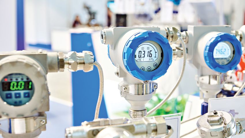
HSB                                          Page 2/6
Pressure Points

For digital gauges, UG-102 further states:

    Digital reading pressure gauges having a wider range of pressure
    may be used, provided the readings give the same or greater
    degree of accuracy as obtained with dial pressure gauges.

The inherent uncertainty in pressure gauges involves:

− the possibility of error of the transducer monitoring the pressure;
− the error in the dial representing the measurement; and
− the human error in reading the gauge.

With a digital pressure gauge the third error is eliminated.

ASME B40.1 defines the accuracy grades of dial (analog) type gauges while ASME B40.7 defines the accuracy grades of
digital gauges. For analog and digital pressure gauges the accuracy for grade 3A (code standard for test gauges) test
gauges have an error of +/-0.25% span over the entire range.

Initially this appears to meet the requirements of UG-102, provided in the example that a 100 psig analog or digital gauge
with a 0.25% accuracy is accurate to within 0.25 psig from 0 to 100 psig in both cases. However, digital pressure gauges are
typically used with a wider range than an analog gauge. In this same example the digital pressure gauge range span might
be from 0-1000 psig with a similar accuracy of 0.25%. This would be accurate to 2.5 psig for the same component being
pressure tested. To address this issue digital pressure gauges can be calibrated to the reading (as grade 3AR) which in
most cases will have smaller errors. In this case, the error will be associated with the actual reading versus the error of the
entire span. As an example, a component with a code hydrostatic test pressure of 75 psig would have the following
associated errors:

− Grade 3A ASME B40.1 Dial type 0-100 psig error 0.25% -> 0.25 psig
− Grade 3A ASME B40.7 Digital type 0-1000 psig error 0.25% -> 2.5 psig
− Grade 3AR ASME B40.7 Digital type 0-1000 psig error 0.25% @ 75 psig -> 0.1875 psig

When using digital pressure gauges for nuclear applications, Section III in NB/NC/ND-6412(b) takes a different approach.
The nuclear code requires that a combined error due to calibration and readability does not exceed 1% of the test pressure.
For example, if the test pressure is 4675 psig and the combined error is 51 psig then it would not meet the code since 1% of
the test pressure would be 46.75 psig.

So the question is, how is the combined error determined? The code states that it is due to readability and calibration. To
look at it we need to understand the digital pressure gauge that is being used.

Think of readability as the scale and marks on an analog gauge. The marks might be in the scale of 5 psig increments and
therefore the readability would be 5 psig. The similar thing could be said about a digital gauge when you look at the
resolution of the gauge. In most cases for a digital gauge readability and resolution are usually the same. For example, with a
digital gauge it may go out 3 decimal places like 0.001. However, if the third decimal place does not give a stable reading
and fluctuates wildly or too fast, then the readability is only 2 decimal places. Most gauges are designed to have their
resolution stable which matches the readability. Note this number is what is on display on the digital output and the number
of increments a pressure change is detected. For most gauges they are about 1 or 5 psig depending on the gauge.

Next comes the error associated with calibration. In this case, we are looking at the accuracy of the gauge. Digital gauges
are certified to an accuracy of +/- some percent of full range. So, a 0-600 psig gauge that is +/-1% is +/-6 psig. If your test
reads 15 psig, that means your reading is between 9 and 21 psig. If you have a 0-50 psig 1% gauge, then a 15 psig reading is
14.5-15.5 psig. You can see how this is similar to the range requirements for analog gauges.
HSB                                          Page 3/6
Pressure Points

Now, let’s look at an example with a test pressure of 1500 psig. Our digital gauge has an unrestricted range of 0-10000 psig
with a readability of 5 psig and an error of +/-0.25%. With 1% of test pressure being 15 psig and the combined error being
25 psig (Error of the full range) + 5 psig (Readability), this digital pressure gauge would not meet the code range
requirements for the specific test pressure to meet Section III code requirements.

Although digital pressure gauges offer many advantages over analog gauges, proper consideration is required to make sure
code range requirements are met.

About the author              Paul Coco joined HSB (Hartford Steam Boiler) in January 2014 and is a graduate of the United States Naval
Paul Coco, Senior Engineer    Academy where he earned a Bachelor of Science degree in aeronautical engineering. Paul also holds a Master’s
paul_coco@hsb.com             Degree of Engineering Management and a Master of Science Degree in Mechanical Engineering. Paul served in
                              the U. S. Navy from 2002 through 2010 which included the role of Reactor Mechanical Division Officer and
                              Training Officer. In 2007 and through 2010, Paul joined the Mechanical Engineering Department at the U. S.
                              Naval Academy where he taught Applied Engineering Thermodynamics for Naval Applications.

                              Paul has also worked as a Reactor Operations Engineer where he conducted detailed technical reviews of
                              nuclear licenses in accordance with federal codes and standards and performed quality assurance inspections
                              on domestic and international nuclear vendors for nuclear safety and related components.

                              Within the HSB Codes and Standards group, Paul is responsible for providing code technical support to internal
                              and external clients with a focus on nuclear construction to ASME Section III and the associated nuclear
                              conformity assessment programs.

History and Status of Grade 91 Creep-Strength-Enhanced Ferritic Steel
Author: Jay Cameron, P.E.
Date: February 11, 2021

Material mechanical properties and allowable stresses
The material specifications’ properties for Grade 91 have been relatively stable since its inclusion in the ASTM (American
Society for Testing and Materials) material specifications. However, due to better processing yields, the specification
minimum tensile strength for forgings was increased in ASTM A182 and A336, and these revised specifications were
adopted in the ASME Code in the 2013 and 2017 Editions, respectively. The Section II, Part D (II-D) allowable stresses were
revised in the 2019 Edition based on these modifications; the allowable stresses in the intermediate-temperature, time-
independent regime were increased up to 6%.

However, the biggest impact to the use of this material happened with the elevated-temperature properties. After other
competing alloys were adopted into the Code, additional data for Grade 91 were obtained and reanalyzed. This resulted in
the Grade 91 allowable stresses at higher temperatures in the time-dependent regime and in thicker sections being reduced
about 7% in 1994. This reduction in properties set in motion global testing of this material — expanding into more and more
heats of materials and evaluations of different product forms (plate, pipe, tube, forgings).

Normally, the allowable stresses published in the Code are based on test data extrapolated out to 100,000 hours. Since it is
not practical to conduct all lab tests for 100,000 hours (over 11 years), standard analytical procedures use shorter-term test
data that is linearized and extrapolated to 100,000 hours. This procedure has proven to serve the industry very well for many
other materials.
HSB Page 4/6
Pressure Points
However, after a significant increase in the amount of data in the data set (including much longer lab tests), the thorough
analysis of the data revealed an anomaly. With these new data for Grade 91, the longer-time data indicated that there was a
change in the slope of the data at lower stresses and longer durations — meaning that the linear extrapolation process used
was not correct. This means that the stress levels of components operating for a long time could cause creep damage and
possibly cracking or fracture at much shorter lifetimes than the 100,000-hour basis. So, in the 2019 Edition, the allowable
stresses were reduced up to 19% at the highest permitted temperatures. [See the following illustration.]
lab test
stress extrapolation
new data
hours to failure
Material chemistry and allowable stresses
Parallel to these mechanical property investigations, EPRI (The Electric Power Research Institute) was conducting a
thorough investigation of the chemistry, microstructure and high-temperature properties of Grade 91 due to some boiler
cracking issues in the field. Their investigation resulted in recommended chemistry changes that could improve the creep
ductility and also creep strength. These chemistry changes were first published in Code Case 2864. Code Cases are
optional, so releasing the improved chemistry by Code Case was solely to provide commercial convenience for the
purchaser. However, the Code Case used the same allowable stresses as for the unmodified chemistry. On June 9, 2019,
a revision to the Code Case was made to increase the allowable stresses roughly 7% higher than what was published
in the 2019 II-D.
Once the final optimum chemistry was negotiated and agreed to in the ASME Code Committees, the chemistry was
included in all the wrought [other than casting] product form material specifications in ASTM. In very quick order, ASME
adopted these revised specifications in the 2019 Edition. The improved chemistry was designated as Type 2 and the
previous chemistry was designated as Type 1. However, the 2019 Section II, Part D was not concurrently revised to explicitly
include Type 2, nor its increased allowable stresses. Therefore, since there was no designation of Type in II-D, which means
that the allowables could be used for either Type — boiler and pressure vessel Manufacturers could use Type 2 without
having to use the Code Case, but with the existing allowable stresses.
Approved for publication in the 2021 Edition of Section II, Part D are additional stress lines for Type 2 — having allowable
stresses roughly 7% higher than those of Type 1. Along with this revision, B31.1 has an action proceeding through the
Committee process to make parallel changes for piping components.
About the author Jay joined HSB (Hartford Steam Boiler) in 1992. He holds a B.S. degree in Mechanical Engineering, Engineering
Jay Cameron, P.E. Mechanics from Worcester Polytechnic Institute and an M.S. degree in Metallurgy from Rensselaer Polytechnic
jay_cameron@hsb.com Institute and is a Registered Professional Engineer.
Jay provides technical assistance for all non-nuclear ASME Boiler and Pressure Vessel Codes and the National
Board Inspection Code (NBIC) and supports clients with design reviews. His technical expertise is in the areas
of pressure vessel design and repair, stress analysis and materials.
Jay currently serves as Chair of BPV II (Materials) and Vice Chair of the Subgroup on Materials (BPV VIII) and is
a member of the Special Committee on Interpretations (BPV VIII). He has presented courses on pressure vessel
design to audiences around the world.HSB Page 5/6 Pressure Points Ask the Engineer Question: When conducting the final pressure test in accordance with UG-99 or UG-100, is it required that the gaskets and bolting installed on all flanges, including temporary closures used just for the pressure test, be identical to the hardware that will be actually installed on the vessel in service? Response: This issue was addressed by the Committee for the first time in Interpretation VIII-1-86-189, published in December 1987. Below is an excerpt from this Interpretation, specifically Questions and Replies (5) and (6). Interpretation: VIII-1-86-189 Subject: Section VIII, Division 1, UG-99 Date Issued: December 14, 1987 File: BC87-426 Question: For purposes of hydrostatic testing, is the gasket considered part of the pressure vessel? Response: Yes. Question: With the concurrence of the owner/user, is it permissible to use gaskets in the required hydrostatic test that have physical characteristics similar to the gaskets used in the design calculations? Response: Yes. As you can see, these questions focused on the gasket being used during the pressure test, with no mention of the bolting. Also, this Interpretation is an example where the Committee issued an opinion without any direct support from the requirements published within the standard. In the 1997 Addenda to Section VIII, Division 1 (VIII-1), a major revision was made to the pressure testing rules essentially prohibiting any leakage from the pressure vessel during the time that the Authorized Inspector conducts his visual examination. This includes all bolted flange assemblies except for temporary test closures. When these rules were added to UG-99(g) and UG-100(d), they did not address whether or not the gaskets and bolting used for the bolted flange(s) during the pressure test were the actual hardware that would be shipped with the vessel. And if not, did the test gaskets and bolting have to conform with the gaskets and bolting that would be used in operation? It has taken 23 years for the Committee to finally clarify this subject in the standard. In the upcoming 2021 Edition to be published this summer, new paragraphs UG-99(l) and UG-100(f) introduce rules for the test gaskets and bolting for custom designed flange assemblies and modified standard flange assemblies where additional calculations are required. During the balloting of this proposal, it was debated at length whether these rules should also apply to standard rated flanges, such as ASME B16.5 and B16.47, but the Committee elected not to invoke these rules for these types of flanges. At the time of the hydrostatic or pneumatic pressure test: 1. Flanges shall be assembled with either an identical gasket used for operation of the pressure vessel, or a gasket with the same outside diameter, inside diameter, thickness, gasket factor (m) and minimum seating stress (y) used in the flange design calculations. 2. The flange shall also be assembled with bolting having identical allowable stress at room temperature as used in the design calculations. As stated earlier, it took many years to approve these rules and in fact, the basic proposal did draw several strong objections. The compromise reached was to add an option allowing the User or his designated agent to waive either one or both of the requirements, so long as they declare as such in the General Notes section of Form U-DR-1 or Form U-DR-2 ( User Design
HSB                                               Page 6/6
Pressure Points

Requirements — See Appendix KK): Both Manufacturers and Users should refer to ASME PCC-1, Paragraph 13 when
considering waiving these requirements. The use of test gaskets and bolting, with properties differing from those used in
the design calculations, do not necessarily verify the integrity of flanged joints.

Note that it is not mandatory for a User Design Specification to be used for VIII-1 construction. However, in order to take
exception to this new rule concerning test gaskets and bolting, a User Design Requirements Form U-DR-1, as given in
Appendix KK, must be supplied containing a statement that these requirements are waived. The form must be signed by the
User or designated agent. However, for the purpose of meeting this requirement in UG-99(l) or UG-100(f), it is not necessary
to fill out any other details requested on the form.

About the author                   Thomas Pastor is currently Vice-President of the Codes and Standards Group for HSB (Hartford Steam Boiler),
Thomas Pastor, P.E.                Global Inspection and Engineering Services Division and has been with HSB for over 34 years. He holds a B.S.
thomas_pastor@hsb.com              and M.S. in Civil Engineering from the University of Connecticut, is a licensed Professional Engineer in the
                                   state of Connecticut and holds a National Board Commission. Tom’s technical expertise is in the area of stress
                                   analysis and pressure vessel design and he has presented over 150 courses and workshops on ASME boiler and
                                   pressure vessel standards to audiences around the world.

                                   Additionally, Thomas Pastor is an ASME Fellow and currently serves on several ASME committees; Senior Vice
                                   President of the Council on Standards and Certification, Member of the Board on Pressure Technology Codes &
                                   Standards, BPV-VIII Standards Committee (Pressure Vessels), Subgroup Design of BPV-VIII and Subgroup
                                   General Requirements of BPV-VIII.

2021 Technical Training and Marketing Events
Dates                         Loction                        Topic
April 6-8                     Malaysia/Virtual               ASME (all Sections)
April 23-24                   India/Virtual                  ASME Section IX
April 27-28                   U.S./Virtual                   ASME Section IX
May 11-12                     U.S./Virtual                   PED
May 18-19                     Malaysia/Virtual               PED and Brexit

     For more information on HSB training and events, please email us at Getinfo@hsb.com

March 2021

Pressure Points is published by                                                                 Editor:
                                                                                                Jennifer Apruzzese
HSB
One State Street                                                                                Contributors:
Hartford, CT 06103                                                                              Paul Coco, Senior Engineer
                                                                                                Jay Cameron, P.E.
GetInfo@HSB.com                                                                                 Thomas Pastor, P.E.
You can also read