PROCEEDINGS OF SPIE Compact hyperspectral instruments
←
→
Page content transcription
If your browser does not render page correctly, please read the page content below
PROCEEDINGS OF SPIE
       SPIEDigitalLibrary.org/conference-proceedings-of-spie

                   Compact hyperspectral instruments

                   Jougla, Paul, Robert, Alice, Lochard, Jérémie, Boyadjian,
                   Joel, Costes, Vincent, et al.

                                  Paul Jougla, Alice Robert, Jérémie Lochard, Joel Boyadjian, Vincent Costes,
                                  Laurie Pistre, Matthieu Castelnau, Damien Rodat, Christian Imbert, Camille
                                  Desjardins, "Compact hyperspectral instruments," Proc. SPIE 11852,
                                  International Conference on Space Optics — ICSO 2020, 118523J (11 June
                                  2021); doi: 10.1117/12.2599609

                                  Event: International Conference on Space Optics — ICSO 2021, 2021, Online
                                  Only

Downloaded From: https://www.spiedigitallibrary.org/conference-proceedings-of-spie on 14 Sep 2021 Terms of Use: https://www.spiedigitallibrary.org/terms-of-use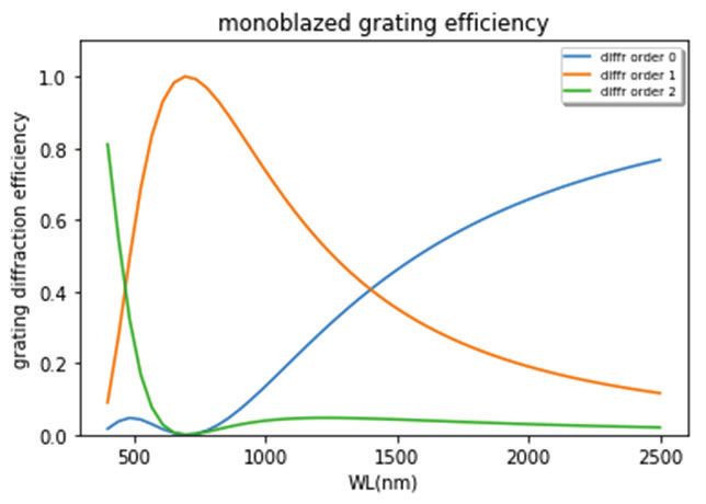
International Conference on Space Optics—ICSO 2020
                Virtual Conference
                30 March–2 April 2021

                                                                             Edited by Bruno Cugny, Zoran Sodnik, and Nikos Karafolas

              Compact hyperspectral instruments

                                      International Conference on Space Optics — ICSO 2020, edited by Bruno Cugny, Zoran Sodnik,
                                                Nikos Karafolas, Proc. of SPIE Vol. 11852, 118523J · © 2021 ESA and CNES
                                                          CCC code: 0277-786X/21/$21 · doi: 10.1117/12.2599609

                                                                        Proc. of SPIE Vol. 11852 118523J-1
Downloaded From: https://www.spiedigitallibrary.org/conference-proceedings-of-spie on 14 Sep 2021
Terms of Use: https://www.spiedigitallibrary.org/terms-of-use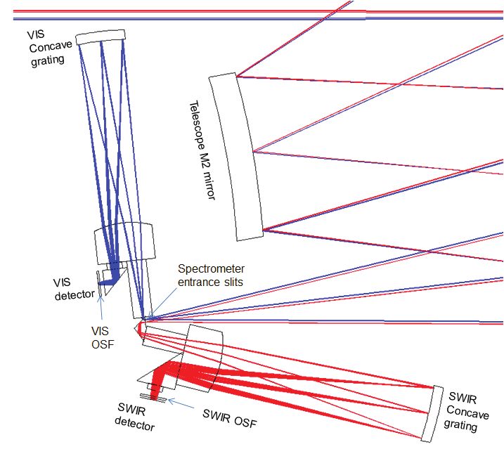
ICSO 2020                                                                                            Virtual Conference
                   International Conference on Space Optics                                                          30 March-2 April 2021

                                         COMPACT HYPERSPECTRAL INSTRUMENTS
                     Paul Jougla *a (paul.jougla@airbus.com), Alice Roberta (alice.robert@airbus.com), Jérémie Locharda
                                  (jeremie.lochard@airbus.com), Joël Boyadjiana (joel.boyadjian@airbus.com)
                         Vincent Costes b, Laurie Pistre b, Matthieu Castelnau b, Damien Rodat b, Christian Imbert b
                                                             Camille Desjardins b
                            a
                             Airbus D&S France - 31, Av. des Cosmonautes – 31 402 Toulouse Cedex 4– France
                                        b
                                          CNES – 18, avenue Edouard Belin – 31 401 Toulouse Cedex 9

                                                                                   ABSTRACT

                    This presented study is initiated in the frame of CNES advanced studies. It aims at providing a better understanding of
                    driving parameters for this type of instruments, and exploring suitable, very compact hyperspectral instruments based on
                    grating spectrometers.
                    First a scalar model for multiblazed gratings is developed, and confronted with more detailed diffraction models.
                    The spectral band is in the range of 400-2500 nm, with a spectral resolution of about 10 nm width. The Ground Sampling
                    Distance (GSD) shall be between 10 and 15m, the Field of View (FOV) shall be larger than 8km, the orbit Height is
                    550km.
                    Three types of instruments are proposed, a common spectrometer with a unique detector, a common spectrometer
                    working in diffraction order 1 for the SWIR, and 2 for the VIS spectral band, and 2 spectrometers within field separa tion.
                    For each instrument the grating blazed profile is optimized, the key instruments parameters computed, and an optical
                    configuration is proposed.
                    The study shows compactness optimization with these three instrument concepts, thanks to an entrance pupil diameter
                    reduction along with better grating diffraction efficiency
                    Keywords: hyperspectral, spectrometer, grating, multiblazed, scalar diffraction model, freeform

                                                                          1. INTRODUCTION
                    Hyperspectral instruments for Earth observation are designed for providing many multispectral images, typically in the
                    range of 200 spectral bands.
                    This presented study is initiated in the frame of CNES advanced studies. It aims at providing a better understanding of
                    driving parameters for this type of instruments, and exploring s uitable, very compact and relevant solutions for the
                    following mission:
                    The spectral band is in the range of 400-2500 nm, with a spectral resolution of about 10 nm width. The Ground Sampling
                    Distance (GSD) shall be between 10 and 15m, the Field of View (FOV) shall be larger than 8km, the orbit Height is
                    550km. A good SNR is requested for the VIS and SWIR wavelengths, considering the following reference luminances:

                    The goal is to design the most compact hyperspectral imager, preferably based on a grating s pectrometer.
                    First a pre-sizing has been performed according to the available detectors, and then grating diffraction efficiency is
                    studied with a scalar model. It demonstrates the need of a multiblazed grating profile to optimize grating diffraction
                    efficiency at the longest wavelengths.

                                                                        Proc. of SPIE Vol. 11852 118523J-2
Downloaded From: https://www.spiedigitallibrary.org/conference-proceedings-of-spie on 14 Sep 2021
Terms of Use: https://www.spiedigitallibrary.org/terms-of-use
ICSO 2020 Virtual Conference
International Conference on Space Optics 30 March-2 April 2021
The instrument is made of a telescope, with one or two slits on its focal plane. It is followed by one or two grating
spectrometer, either Dyson or Offner (cf. [1], [2], [3]). The different images of the slit in the various wavelengths are
imaged on the Focal Plane Array (FPA).
The following three options are studied for the spectrometer:
- A unique spectrometer covering the whole waveband with the diffraction order number 1
- A unique spectrometer, which uses diffraction order 1 for the SWIR wavebands, and diffraction order 2 for the
visible wavelengths
- Two separate spectrometers, for the VIS and for the SWIR sub wavebands.
Choice of the detector:
MCT is needed if a single detector is implemented to cover the whole spectral range. In case of spectral
splitting and use of two detectors to cover the whole spectral range, the use of a silicon detector for VNIR
band and a MCT one for SWIR band may be preferred for cost reason. Nevertheless, a pixel pitch of 18 μm is
considered for this study, which can be the result of a macropixel if silicon pixel pitch is found too small.
2. GRATING PROFILE OPTIMIZATION
The gratings of all the instruments encountered in this study have a period much larger than wavelengths. Grating
diffraction efficiency can therefore be best computed with a simplified scalar model.
The Optical Path Difference (OPD) added by the blazed grating to the electrical field phase is given in figure below:
Figure 1. Optical path difference (OPD) added by a mono blazed grating
An incident wave plane is diffracted in several diffraction orders.
Intensity in the kth diffraction order is given by the classical formula:
ఒ
ܫԢ ൌ ;ܿ݊݅ݏ൬ߨ ή ቀ െ ݇ቁ൰ (1)
ఒ
In order to balance efficiency in VNIR and SWIR parts of the spectrum the best compromise is to choose the blazed
wavelength equal to 700nm:
Proc. of SPIE Vol. 11852 118523J-3
Downloaded From: https://www.spiedigitallibrary.org/conference-proceedings-of-spie on 14 Sep 2021
Terms of Use: https://www.spiedigitallibrary.org/terms-of-useICSO 2020 Virtual Conference
International Conference on Space Optics 30 March-2 April 2021
Figure 2. Diffraction efficiency of a monoblazed grating at 700nm, scalar model
Wavelength range covers more than 2 decades: a monoblazed grating is not capable of a high efficiency over such a
large range of wavelengths, transmission of the instrument would be lower than 10% at the 2 edges of the spectrum,
leading to very low SNR. This is critical for the SWIR wavelengths, for which the luminance tends to be lower than in
the visible part of the spectrum.
In order to optimize the transmission all over the instrument spectrum it is necessary to design a multiblazed grating
profile (ref [4]).
We develop here a dedicated scalar model of such a multiblazed grating, in order to optimize the grating profile and the
instrument transmission.
The optical path difference added by the grating is a function with periodicity a, made of N segments with number j=1 t o
N
Figure 3. Multiblazed grating profile: the profile is made of N segments
On segment number j the OPD is given by:
௬ି௬ ೕ
ܱܲܦ ሺݕሻ ൌ ή ߣ + ߜ (2)
(Oj would be the blazed wavelength in the case this segment was extended to the whole period a of the grating.)
Proc. of SPIE Vol. 11852 118523J-4
Downloaded From: https://www.spiedigitallibrary.org/conference-proceedings-of-spie on 14 Sep 2021
Terms of Use: https://www.spiedigitallibrary.org/terms-of-useICSO 2020 Virtual Conference
International Conference on Space Optics 30 March-2 April 2021
We arbitrarily choose ߜଵ ൌ Ͳ, and we constrain the profile to be a continuous function, for manufacturability reasons.
ఒೕ ାఒೕశభ
Therefore ߜାଵ ൌ ߜ .
ଶ
The multiblazed grating profile is therefore completely described by the set of all the ߣ, for j=1 to N.
Let’s consider a plane wave incident on the grating at normal incidence. The grating is on the (x,y) plane and the incident
wave propagates along the Z axis. The grating grooves are aligned with X axis.
The incident electrical field is described by: ܧሺݔǡ ݕሻ ൌ ͳ. After the grating the electrical field is ܧሺݔǡ ݕሻ ൌ ݁ ήைሺ௬ሻ
As OPD(y) is a-periodic, the Fourier series coefficients give the electrical field at infinite.
We therefore compute the Fourier transform for each of the N segments, and then add them coherently to get the
electrical field in diffraction order k:
ഃೕ ೕ
ଵ ଶగ൬ ି ൰ గ ఒೕ
ܧԢ ൌ σே
ୀଵ ݁
ഊ ೌ ή ܿ݊݅ݏ൬ ή ቀ െ ݇ቁ൰ (3)
ே ே ఒ
Intensity is then given by the square of the norm of the electrical field:
തതതതത
ܫԢ ൌ ܧԢ ή ܧᇱ (4)
We used Python to optimize the multiblazed grating profile for each of the applications described here after.
The goal is to design the ideal multi-blazed profile, which gives the best theoretically grating efficiency.
3. INSTRUMENT OPTIMIZATION
3.1 Instrument with one grating spectrometer, used in the 1st diffraction order
Grating optimization:
As mentioned before a monoblazed grating cannot cover efficiently the whole spectral band [400,2500nm] with
diffraction order #1: diffraction efficiency is 100% for the blazed wavelength, but drops on the 2 edges of the spectral
band. The goal is to modify the grating blazed profile in order to balance efficiency all over the spectral band, at the
expense of the peak value. More specifically we put more weight on the higher wavelengths, for which scene luminance
is lower than for the VIS wavelengths.
This python optimization led to the profile shown below, and the related diffraction efficiency for the first diffraction
orders:
Proc. of SPIE Vol. 11852 118523J-5
Downloaded From: https://www.spiedigitallibrary.org/conference-proceedings-of-spie on 14 Sep 2021
Terms of Use: https://www.spiedigitallibrary.org/terms-of-useICSO 2020 Virtual Conference
International Conference on Space Optics 30 March-2 April 2021
Figure 4. Multiblazed grating profile optimized for the [400,2500nm] spectral band, diffraction efficiency for this
multiblazed grating. T he five wavelengths used for the multiblazed profile are: [623, 623, 883, 2965, 3504] nm
The simplified scalar model is very convenient to quickly optimize the grating profile. A more detailed model, such as
the one used by software PC grate, is more realistic, and takes the polarization into account.
Figure below shows the two models fit correctly, and that the scalar approximation is valid as wavelength is smaller than
grating period. At shorter wavelengths the two models do not agree well and further investigation shall be made in order
to optimize the diffraction efficiency in this region. Ref [4] shows such a grating is possible.
Figure 5. Multiblazed grating profile optimized for the [400,2500nm] spectral band: comparison of scalar model and PC
grate model
T able 1. T he instrument key parameters are calculated from SNR budget and taking into account the grating efficiency:
Proc. of SPIE Vol. 11852 118523J-6
Downloaded From: https://www.spiedigitallibrary.org/conference-proceedings-of-spie on 14 Sep 2021
Terms of Use: https://www.spiedigitallibrary.org/terms-of-useICSO 2020 Virtual Conference
International Conference on Space Optics 30 March-2 April 2021
Optical design:
In order to achieve the UV SNR specification a large pupil (diameter 350mm) has to be accomodated.
This leads to a very large telescope, whereas the spectrometer volume is much smaller, whatever the type of design:
Dyson spectrometer or Offner spectrometer.
In order to optimize the telescope volume the best choice is to design a 3 mirrors telescope, with freeform mirrors.
In the case of the Offner spectrometer, the volume of the spectrometer is optimized with 2 freeform mirrors. The convex
grating is ruled on a spherical surface: choosing a freeform grating marginally reduces the global volume of the
instrument, and keeping a spherical grating is best for manufacturability.
As for the Dyson spectrometer a spherical grating permits a quite compact spectrometer. Aspherizing it does not help in
reducing notably the spectrometer volume, which is , again, negligible vs. telescope volume.
100.00 MM
Figure 6. T elescope for the first instrument option: 3 freeform mirrors, volume = 100 liters
T able 2. Offner spectrometer and Dyson spectrometer comparison for the first instrument option
Offner spectrometer Dyson spectrometer
Volume = 1.5 liters Volume = 0.5 liters
Mirrors: freeform Field lens: aspheric, fused silica
Grating: convex, spherical, period = 35μm Spherical, concave, period = 58μm
Proc. of SPIE Vol. 11852 118523J-7
Downloaded From: https://www.spiedigitallibrary.org/conference-proceedings-of-spie on 14 Sep 2021
Terms of Use: https://www.spiedigitallibrary.org/terms-of-useICSO 2020 Virtual Conference
International Conference on Space Optics 30 March-2 April 2021
An OSF (Order Sorting Filters) will be placed just before the FPA, in order to decrease the level of straylight due to
neighbor grating diffraction orders.
The Dyson shall be folded before the FPA, in order to accommodate the detector.
The figure below gives a view of the telescope and the Offner spectrometer:
Figure 7. instrument for the first instrument option
3.2 Instrument with one grating spectrometer, using two diffraction orders
Grating optimization
The previous design volume is quite big: its large entrance pupil compensates the low grating diffraction efficiency.
As waveband covers more than 2 decades it is possible to dedicate shorter wavelengths to grating diffraction order 2, and
longer ones to diffraction order 1. The waveband is therefore split into two sub wavebands, imaged on two dedicated
detectors. The limit between the 2 wavebands is fixed at 1000nm, so that a silicon detector is able to image lower
wavelengths. With this option we get better grating diffraction efficiency:
Figure 8. Multiblazed grating profile optimized for the [400,2500nm] spectral band. [400,1000nm] spectral band uses
diffraction order number 2, [1000,2500nm] spectral band uses diffraction order number 1. On the right: Diffraction
efficiency for this multiblazed grating. T he five wavelengths used for the multiblazed profile are:
[807, 829, 1565, 1869, 1974]nm
Proc. of SPIE Vol. 11852 118523J-8
Downloaded From: https://www.spiedigitallibrary.org/conference-proceedings-of-spie on 14 Sep 2021
Terms of Use: https://www.spiedigitallibrary.org/terms-of-useICSO 2020 Virtual Conference
International Conference on Space Optics 30 March-2 April 2021
As diffraction efficiency gets better in the SWIR waveband, it is possible to work with a smaller entrance pupil
instrument: entrance pupil diameter is now 300mm:
T able 3. T he instrument key parameters are calculated from SNR budget and taking into account the grating efficiency:
In this case, pupil size is well balanced between UV and SWIR SNR needs.
Optical design:
Telescope:
- Similar to the first solution: 3 freeform mirrors
- scale down: volume = 81 liters
Spectrometer:
The two useful grating orders are superimposed over spectral range and split before focal planes using a Dichroic Beam
Splitter (DBS). The DBS reflects wavelengths shorter than 1000nm, and transmits wavelengths larger than 1000nm. Th e
two sub wavebands are then imaged on a dedicated detector.
The spectrometer is an Offner spectrometer. Indeed it would be very difficult to accommodate the DBS in a Dyson
spectrometer:
Figure 9. spectrometer for the second instrument option: 2 freeform mirrors, spherical convex grating with period 35μm.
Separation VIS/SWIR with a dichroic plate. Spectrometer volume is 1.5 liters
Proc. of SPIE Vol. 11852 118523J-9
Downloaded From: https://www.spiedigitallibrary.org/conference-proceedings-of-spie on 14 Sep 2021
Terms of Use: https://www.spiedigitallibrary.org/terms-of-useICSO 2020 Virtual Conference
International Conference on Space Optics 30 March-2 April 2021
The spectral resolution is 10 nm over SWIR band and 5 nm over VNIR band. VNIR SNR is thus computed using
binning over two spectral samples. It may be interesting to have access to this improved spectral resolution of 5 nm, even
with degraded SNR.
The figure below gives a view of the telescope and the Offner spectrometer:
100.00 MM
Figure 10. telescope + spectrometer for the second instrument option
3.3 Instrument with two grating spectrometers
To further improve compactness, and thus grating diffraction efficiency another option is to use two spectrometers, with
two gratings: one spectrometer dedicated to VIS ([400-1000]nm), and one spectrometer dedicated to SWIR wavelengths
([1000-2500]nm). It is possible to drastically improve gratings’ diffraction efficiency:
Grating optimization:
Grating for VIS spectrometer ([400-1000]nm):
A monoblazed grating calculated the wavelength 580nm gives:
Figure 11. Diffraction efficiency with scalar model of a monoblazed grating over the [400-1000nm] spectral band. Blazed
wavelength is 580 nm.
Proc. of SPIE Vol. 11852 118523J-10
Downloaded From: https://www.spiedigitallibrary.org/conference-proceedings-of-spie on 14 Sep 2021
Terms of Use: https://www.spiedigitallibrary.org/terms-of-useICSO 2020 Virtual Conference
International Conference on Space Optics 30 March-2 April 2021
A few trials showed that it is not possible to get a better efficiency with the use of a multiblazed grating. Besides it is
better to use a classical monoblazed grating if possible, for cost reasons.
Grating for SWIR spectrometer ([1000-2500]nm):
Multiblazed profile is necessary so that grating diffraction efficiency gets higher for wavelengths with the smallest
luminance (the longer the wavelength, the larger the diffraction efficiency shall be).
Multiblazed grating profile, and the related diffraction efficiency is given in the plots below:
Figure 12. Multiblazed grating profile optimized for the [1000,2500nm] spectral band. On the right: Diffraction efficiency
for this multiblazed grating. T he five wavelengths used for the multiblazed profile are: [911, 1579, 1590, 2784, 3953] nm
Optical design:
Splitting can be implemented at slit level, with spectral splitting using a Dichroic Beam Splitter or with spatial splitting
using two slits in the telescope focal plane. The « in-the-field » splitting increases telescope ALT field of view, but saves
a dichroic beam splitter and its related drop of transmission. Polarization sensitivity is also improved: this option is
preferred.
T able 4. T he instrument key parameters are calculated from SNR budget and taking into account the grating efficiency:
With these data and some margin, instrument dimensioning gives Entrance Pupil Diameter of 236mm to reach the SNR
specification at 2200nm.
The telescope design is similar to the 2 cases described before. The volume is optimized, thanks to a smaller entrance
pupil size.
Telescope volume is 50 liters
Proc. of SPIE Vol. 11852 118523J-11
Downloaded From: https://www.spiedigitallibrary.org/conference-proceedings-of-spie on 14 Sep 2021
Terms of Use: https://www.spiedigitallibrary.org/terms-of-useICSO 2020 Virtual Conference
International Conference on Space Optics 30 March-2 April 2021
The gap between the two slits is set to 1.5 mm in order to ease separation of the 2 sub wavebands.
The spectrometers are Dyson spectrometers: as we need two such spectrometers the Dyson has the advantage to offer the
smallest volume, and the smallest number of optical components.
Each Dyson spectrometer includes a silica plano-convex lens, with an aspherical convex face, and a concave grating.
T able 5. VIS and SWIR Dyson spectrometers characteristics:
VIS spectrometer SWIR spectrometer
grating Substrate: Spherical shape, concave Substrate: Spherical shape, concave
Radius of curvature = 143mm Radius of curvature = 165mm
Grating period = 49.5μm Grating period =62μm
Spectrometer length 150mm 160mm
The SWIR spectrometer tends to be longer than the VIS spectrometer, due to the larger waveband it covers.
Figure below depicts the optical layout of the whole instrument for this concept:
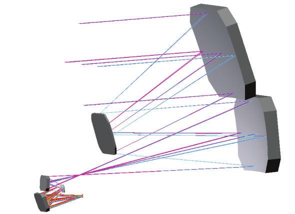
Figure 13. instrument for the third option: one telescope and two Dyson spectrometers for the VIS & SWIR sub spectral
bands. On the right: zoom on the spectrometers
The 2 wavebands are split by using small prisms after the slit plane. The SWIR path is thus folded, in order to optimize
the instrument global volume:
OSF (Order Sorting Filters) are implemented in front of each detector.
Proc. of SPIE Vol. 11852 118523J-12
Downloaded From: https://www.spiedigitallibrary.org/conference-proceedings-of-spie on 14 Sep 2021
Terms of Use: https://www.spiedigitallibrary.org/terms-of-useICSO 2020 Virtual Conference
International Conference on Space Optics 30 March-2 April 2021
4. CONCLUSION:
Hyperspectral instruments with a large spectral band and using a grating spectrometer have to deal with the diffraction
efficiency of the grating, which is the main driver for the instrument volume and compactness optimization. A low
diffraction efficiency grating implies a large telescope pupil: the s ize of the instrument is driven by the telescope size
rather than by the spectrometer.
For instruments covering VIS to SWIR spectral bands we demonstrate the interest to split the spectral band into 2
spectrometers, with dedicated and customized grating profiles. Grating efficiency is maximized, leading to a smaller
instrument.
Besides we demonstrate that for this class of application, where instrument volume is driven by the telescope volume, a
classical, spherical substrate for the grating permits a good compactness. Using a freeform substrate is not necessary.
T able 6. comparison of the three options
solution description entrance pupil Number of Telescope volume
diameter (mm) detectors (liters)
1 common spectrometer, 1st 350 1 100
diffraction order
2 common spectrometer, 300 2 81
diffraction order 1 and 2
3 dedicated spectrometer to 236 2 50
each sub waveband
REFERENCES
[1] J. Dyson, "Unit magnification optical system without Seidel aberrations," J. Opt. Soc. Am. 49(7), 713-716
(1959).
[2] L. Mertz, "Concentric spectrographs," Appl. Opt. 16(12), 3122-3124 (1977).
[3] A. Offner, “New concepts in projection mask aligners,” Opt. Eng. 14(2), 130-132 (1975).
[4] B. Van Gorp, P. Mouroulis, D.W. Wilson, R.O. Green, “Design of the compact wide swath imaging
spectrometer (CWIS),” Proc. SPIE, 9222, 92220C (2014).
Proc. of SPIE Vol. 11852 118523J-13
Downloaded From: https://www.spiedigitallibrary.org/conference-proceedings-of-spie on 14 Sep 2021
Terms of Use: https://www.spiedigitallibrary.org/terms-of-useYou can also read