DETERMINATION OF PAPER WRAPPER BURN SPEED - CORESTA Recommended Method No. 53 Physical Test Methods Sub-Group
←
→
Page content transcription
If your browser does not render page correctly, please read the page content below
Cooperation Centre for Scientific Research
            Relative to Tobacco

  Physical Test Methods Sub-Group

CORESTA Recommended Method
          No. 53

    DETERMINATION OF
PAPER WRAPPER BURN SPEED

              January 2019
CORESTA RECOMMENDED METHOD Nº 53
Title:
DETERMINATION OF PAPER WRAPPER BURN SPEED
Status: Valid
Note: This document will be periodically reviewed by CORESTA
Document history:
Date of review Information
May 2002 Version 1
Version 2 - Editorial changes in line with the CORESTA Guidelines
January 2019
for Writing a CRM
CRM No. 53 – January 2019 Page 2/14CORESTA RECOMMENDED METHOD N° 53
DETERMINATION OF PAPER WRAPPER BURN SPEED
(January 2019)
0. INTRODUCTION
The paper wrapped around manufactured cigarettes, roll your own and tubed products is a
vital component of the cigarette or fine-cut smoking article. The measurement of burn speed
has been carried out using a variety of test procedures by the paper manufacture, paper
conversion and tobacco industries for many years. The purpose of this method is to provide a
reproducible laboratory procedure for the measurement of paper wrapper burn speed.
1. FIELD OF APPLICATION
This method is applicable to all paper wrappers in the form of bobbins, leaflets and rolls and
wrapper spills removed from finished tobacco products. It is designed for the testing of paper
wrappers and must not be used for the testing of tobacco products. Paper wrapper burn speed
is a characteristic of the paper and is not intended to be used to predict smoke yields.
2. REFERENCES
ISO 186
Paper and board – Sampling to determine average quality.
ISO 187
Paper, board and pulps – Standard atmosphere for conditioning and testing and procedure
for monitoring the atmosphere and conditioning of samples.
3. DEFINITIONS
For the purposes of this CORESTA Recommended Method, the following definitions apply.
3.1 Paper Wrapper
Paper specially prepared and supplied in a form suitable for enclosing the tobacco in
manufactured cigarettes, roll your own and tubed products.
3.2 Burn Speed
The time needed for a paper wrapper to smoulder a length of 15 mm under controlled
conditions.
3.3 Laboratory Sample
The sample of paper wrapper intended for laboratory inspection or testing and which is
representative of the paper wrapper to be tested.
CRM No. 53 – January 2019 Page 3/143.4 Test Sample
Paper wrapper for testing taken at random from the laboratory sample and which is
representative of each of the increments making up the laboratory sample.
3.5 Test Piece
An individual strip of paper wrapper for testing.
4. PRINCIPLE
The test piece is rolled and placed in a controlled environment where non-flame ignition is
used to begin the smoulder process. The time taken to smoulder between two set points is
measured.
5. APPARATUS
5.1 Testing Box
The testing box is illustrated in Figure 1.
Figure 1. Testing Box
120 mm
200 mm P
120 mm
P = 25 mm dia.
Q = 120 mm dia.
120 mm Q
300 mm
400 mm
500 mm
A testing box shall be constructed from transparent material and internally shall measure
approximately 500 mm wide × 400 mm deep × 300 mm high. The front of the box shall
contain a 120 mm diameter circular hole to allow the operator to insert the roll of paper. The
centre of the hole shall be 120 mm from both the left-hand side and the top of the box. The
top of the box shall have a small hole, 25 mm in diameter, to allow circulation placed 120 mm
from the right hand side and 200 mm from the front of the box. Both holes shall be left
uncovered at the time of the test.
Note: In case of automatic or semi-automatic test piece ignition, an additional opening,
approximately 25 mm in diameter, shall be included on the left hand side.
CRM No. 53 – January 2019 Page 4/145.2 Needle
A polished stainless steel needle shall be used with a diameter of 2,5 mm and a length
of 100 mm.
5.3 Digital Timer
The digital timer shall have an accuracy of 0,1 second.
5.4 Paper Holder
The paper holder shall consist of two components, the holder and the plug that are
illustrated in Figures 2a and 2b.
1. The holder, Figure 2a, shall be a hollow stainless steel tube 25 mm long with an
inner diameter of 4 mm and an outer diameter of 12 mm. A solid tube, diameter
4 mm, shall be attached at right angles to the hollow tube. This solid tube attaches
the holder to a base, which ensures that the holder is held horizontally and securely
and that the overall height from the floor of the test box to the centre of the paper
holder is 140 mm.
2. The plug, Figure 2b, is in the form of a tee, with an overall length of 25 mm. The
top of the plug shall be 5 mm thick and 12 mm diameter; the bottom of the plug
shall be 20 mm in length with a diameter of 3,9 mm and shall be a snug fit into the
hole of the holder. A hole, 2 mm in diameter, shall be in the centre of the 25 mm
length of the plug.
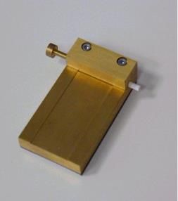
5.5 Paper Holder Base
The paper holder base must ensure that the paper holder is held horizontally and
securely and that the overall height from the floor of the test box to the centre of the
paper holder is 140 mm ± 0,2 mm. The length of the solid tube from the holder will
vary according to the design of the paper holder base.
An example of a paper holder base is shown in Figure 3. It has a flat base plate of
dimension 65 mm × 65 mm × 3 mm. A tube is fixed vertically to the centre of the base
plate of length 94 mm and inner diameter 4,1 mm to take the solid tube from the holder.
Note: The flat base plate measures 3 mm, the filled tube 37 mm, the length of the solid
tube 94 mm and the midpoint of the holder 6 mm, giving 140 mm as required in total.
CRM No. 53 – January 2019 Page 5/14Figure 2a. The Holder
25 mm
4 mm 12 mm
4 mm
Figure 2b. The Plug
5 mm
3.9 mm 2 mm 12 mm
20 mm
CRM No. 53 – January 2019 Page 6/14Figure 3. A Paper Holder Base
13 mm
4.1 mm
97 mm
37 mm
3 mm
65 mm x 65 mm
5.6 Fume Hood
A laboratory fume hood capable of holding the testing box shall be used.
6. SAMPLING
Provide a laboratory sample by a suitable sampling scheme such as that given in ISO 186.
This sample will normally contain paper samples taken from different parts of the population.
Make up the test sample required for the test by randomly selecting paper from the different
parts of the population represented in the laboratory sample.
CRM No. 53 – January 2019 Page 7/147. METHOD
7.1 Sample Handling
Non-talc surgical or cotton gloves shall be used at all times when handling the test
pieces.
7.2 Laboratory Conditioning
Condition the test pieces, prior to measurement, in a conditioning enclosure set at
23 °C ± 1 °C and 50 % ± 2 % relative humidity (RH) in accordance with ISO 187. Samples
shall be held such that the conditioning air has free access to all their surface.
Note: In laboratories unable to use the conditions given in ISO 187, the conditions
22 °C ± 1 °C and 60 % ± 2 % RH given in ISO 3402 may be used. In this case a note
shall be included in the test report.
7.3 Sample Marking
The sample marking is illustrated in Figure 4.
The test piece from the test sample shall be cut in the machine direction, approximately
60 mm long and a minimum of 26 mm and a maximum of 28 mm wide.
Draw two parallel lines 15 mm apart along the length of the paper test piece. Line A
illustrates the 5 mm depth of insertion from the holder edge. The edge, to be inserted
into the holder shall be the gummed edge, if applicable. Line B shall be drawn 7 mm
from the holder edge and line C 22 mm from that edge. A minimum width of 26 mm
gives 4 mm of paper between line C and the edge to be ignited and a maximum width of
28 mm gives 6 mm of paper between line C and the edge to be ignited.
The distance between lines B and C shall be 15 mm ± 0,3 mm.
The pencil lines shall be drawn on the wire-side of the paper where this can be
determined. Where the wire-side cannot be determined a note shall accompany the test
result to this effect.
7.4 Box preparation
7.4.1 The holder shall be placed in the centre of the floor area of the testing box. The
paper holder base into which the holder is inserted must ensure that the paper
holder is held horizontally and securely and directed towards the 120 mm
diameter hole. The overall height from the floor of the test box to the centre of
the paper holder is 140 mm.
7.4.2 The box shall be placed in the fume hood. The airflow in the fume hood shall be
switched off at the time of the test.
The fume hood may be switched on between groups of tests to exhaust any fumes.
CRM No. 53 – January 2019 Page 8/14Figure 4. Sample Marking
Edge to be ignited
Line C
26 mm to 28 mm
Machine direction
Direction of rolling
22 mm
Line B
A
7 mm
5 mm
Gummed edge, if applicable
Edge inserted into the holder
60 mm
7.5 Test Piece Preparation
The test piece shall be placed, with the lines on the outside, i.e. wire-side outside, on the
needle and firmly and evenly rolled round the needle to form a small roll. The edge to
be inserted into the holder when rolled shall be at the end of the needle. The edge to be
ignited when rolled shall be at the body of the needle. This is illustrated in Figure 5.
Figure 5. Sample Preparation
Steel needle Rolled and marked test piece
C B A
Ignition end Holder end
All test pieces shall be rolled as firmly as possible and to the similar degree of tension.
This rolling may be assisted by means of a simple jig, which is described in Annex A.
Fit the plug into the holder. Insert the roll at the open end of the needle into the holder
to a depth of 5 mm given by the plug.
Slide the needle from the roll, retaining the tight roll within the holder. Carefully push
the roll to the correct position against the plug. Ensure that the plug is in place during
the test.
This is illustrated in Figure 6.
Split needle
CRM No. 53 – January 2019 Page 9/147.6 Position of the Paper Holder
The holder containing the paper roll shall be placed in the paper holder base in the
testing box such that the paper roll is horizontal and parallel to the front side of the box
with the ignition end facing left towards the hole in the front of the box. The overall
height from the floor of the test box to the centre of the holder shall be 140 mm.
7.7 Ignition
Switch off the fume hood and ignite the end of the roll using non-flame ignition.
Ensure the end of the roll is smouldering over the whole surface and does not flare.
Close the fume hood.
7.8 Measurement
Using the digital timer, measure the time taken for the roll to smoulder between the two
lines C and B. The time shall be measured to the nearest 0,1 second. The observation
shall be taken from the front side.
At the end of the test remove any residue from the test holder using tissue, filter paper
or tweezers and ensure that the hole is clean before the next test.
This test procedure shall be repeated on ten test pieces for each test sample. The
reported result is the mean value and standard deviation from the ten individual
measurements.
CRM No. 53 – January 2019 Page 10/14Figure 6. Assembly of the Plug, Holder and Rolled Test Piece
The Plug The Holder Rolled and marked test piece
A B C
The Plug, Holder and Test Piece during assembly
B C
Plug, Holder and Test Piece after assembly
CRM No. 53 – January 2019 Page 11/148. TEST REPORT
The test report shall show the method used and the results obtained. It shall also mention any
operating conditions not specified in this CORESTA Recommended Method, or regarded as
optional, as well as any circumstances that may have influenced the results. The test report
shall include all details required for complete identification of the sample.
8.1 Characteristic Data about the Paper
This may include:
Name of manufacturer
Country of manufacture
Brand name and sub-brand name
Pack number (of that product sampled that day)
Marks on any tax stamp
Printed classification
8.2 Sampling
Type of sampling procedure
Date of sampling
Place of purchase or sampling, if known
Sampling point (e.g. address of retail outlet or machine number), if known
8.3 Description of Test
Reference to this CORESTA Recommended Method
Date of test
Number of test pieces tested in the entire determination
Temperature and relative humidity in the testing room at the time of testing
Atmospheric pressure during testing
8.4 Test Results
The following data shall be given for each of the test samples.
The burn speed in s/15 mm for each of the ten individual test pieces rounded to
0,1 s/15 mm
The mean and standard deviation of the burn speed for the ten test pieces in s/15 mm
rounded to 0,1 s/15 mm
CRM No. 53 – January 2019 Page 12/149. REPEATABILITY AND REPRODUCIBILITY
The precision of this test method is given in the table below.
Burn Speed Repeatability Reproducibility
Mean
Level sr r sR R
s/15 mm
1 26,3 0,29 0,82 1,00 2,83
2 30,8 0,50 1,40 1,70 4,81
3 37,2 0,43 1,22 2,08 5,89
4 43,0 0,50 1,41 3,06 8,65
5 52,1 0,68 1,91 4,80 13,57
Where sr and sR are unbiased estimates of standard deviation.
The difference between two results with the same operator using the same equipment on
identical test items within the same laboratory will exceed the repeatability, r, on average in
no more than one in twenty cases in the normal and correct operation of the method.
The difference between two results with a different operator using different equipment on
identical test items within different laboratories will exceed the reproducibility, R, on average
in no more than one in twenty cases in the normal and correct operation of the method.
These values may be applied within a range of 26 to 52 seconds. They were determined from
a uniform level experiment conducted in April/May 2001 involving 12 laboratories and 5
paper samples. The data from one of the paper samples tested by two of the laboratories were
detected as outliers and deleted.
CRM No. 53 – January 2019 Page 13/14ANNEX A (INFORMATIVE)
Figure A.1. A Jig to Facilitate Test Piece Rolling
Paper
guide lines
4mm hole
The concept of a jig to facilitate test piece rolling is illustrated in Figure A.1. This requires
the use of a needle that is split from one end for about 30 mm of its length rather than the
plain needle described in paragraph 7 of this Method. The needle (split not shown) is pushed
into the 4 mm hole with the split in line with the slit in the jig. The test piece is placed
between the guidelines and slid through to the other side of the 4 mm hole through the split in
the needle. The needle is then rotated to roll the test piece. The split needle is removed and
the rolled test piece is ready for transfer to the holder.
Figure A.2. Further Refined Jig for Rolling the Test Piece
Split
Pusher
Pusher needle
Rolled
test piece
Paper
guidelines Spacer
A further refinement of the jig is shown in Figure A.2.
A spacer is inserted at one side of the 4 mm hole and the split needle is inserted at the
opposite side. This ensures that the split needle is in the correct position. After rolling, the
split needle and the spacer are carefully removed and the pusher inserted to transfer the rolled
test piece to the holder.
CRM No. 53 – January 2019 Page 14/14You can also read