Process air centrifugal fans - operating instructions
←
→
Page content transcription
If your browser does not render page correctly, please read the page content below
english

Process air centrifugal fans
Assembly instructions

PRdry & PR-T ranges and PL range impellers

L-BAL-031-GB 2022/08 Index 015   Part.-No. 00292347-GB

Assembly instructions Process air centrifugal fans

            Content
        1   General notes . . . . . . . . . . . . . . . . . . . . . . . . . . . . . . . . . . . . . . . . . . . . . . . . . . . . . . . . . . . . .       4
            1.1 Scope of documentation . . . . . . . . . . . . . . . . . . . . . . . . . . . . . . . . . . . . . . . . . . . . . . . .                    4
            1.2 Structure of the assembly instructions . . . . . . . . . . . . . . . . . . . . . . . . . . . . . . . . . . . . .                          4
            1.3 Target group . . . . . . . . . . . . . . . . . . . . . . . . . . . . . . . . . . . . . . . . . . . . . . . . . . . . . . . . .            4
            1.4 Exclusion of liability . . . . . . . . . . . . . . . . . . . . . . . . . . . . . . . . . . . . . . . . . . . . . . . . . . .              4
            1.5 Copyright . . . . . . . . . . . . . . . . . . . . . . . . . . . . . . . . . . . . . . . . . . . . . . . . . . . . . . . . . . .           4

        2   Safety instructions . . . . . . . . . . . . . . . . . . . . . . . . . . . . . . . . . . . . . . . . . . . . . . . . . . . . . . . . .         5
            2.1 Intended use . . . . . . . . . . . . . . . . . . . . . . . . . . . . . . . . . . . . . . . . . . . . . . . . . . . . . . . .              5
            2.2 Improper use . . . . . . . . . . . . . . . . . . . . . . . . . . . . . . . . . . . . . . . . . . . . . . . . . . . . . . . .              5
            2.3 Explanations of symbols . . . . . . . . . . . . . . . . . . . . . . . . . . . . . . . . . . . . . . . . . . . . . . . .                   6
            2.4 Product safety . . . . . . . . . . . . . . . . . . . . . . . . . . . . . . . . . . . . . . . . . . . . . . . . . . . . . . .              6
            2.5 Requirements placed on the personnel / due diligence . . . . . . . . . . . . . . . . . . . . . . . .                                      6
            2.6 Work on the device . . . . . . . . . . . . . . . . . . . . . . . . . . . . . . . . . . . . . . . . . . . . . . . . . . .                  6
            2.7 Modifications / interventions in the device . . . . . . . . . . . . . . . . . . . . . . . . . . . . . . . . . .                            7
            2.8 Operator’s obligation of diligence . . . . . . . . . . . . . . . . . . . . . . . . . . . . . . . . . . . . . . . . .                      7
            2.9 Employment of external personnel . . . . . . . . . . . . . . . . . . . . . . . . . . . . . . . . . . . . . . . .                          7

        3   Product overview . . . . . . . . . . . . . . . . . . . . . . . . . . . . . . . . . . . . . . . . . . . . . . . . . . . . . . . . . .          8
            3.1 Application operational area . . . . . . . . . . . . . . . . . . . . . . . . . . . . . . . . . . . . . . . . . . . . .                    8
            3.2 Note on the ErP directive . . . . . . . . . . . . . . . . . . . . . . . . . . . . . . . . . . . . . . . . . . . . . . .                   8
            3.3 Transport . . . . . . . . . . . . . . . . . . . . . . . . . . . . . . . . . . . . . . . . . . . . . . . . . . . . . . . . . . .           8
            3.4 Storage . . . . . . . . . . . . . . . . . . . . . . . . . . . . . . . . . . . . . . . . . . . . . . . . . . . . . . . . . . . . .         9
            3.5 Disposal / recycling . . . . . . . . . . . . . . . . . . . . . . . . . . . . . . . . . . . . . . . . . . . . . . . . . . .               10

        4   Mounting . . . . . . . . . . . . . . . . . . . . . . . . . . . . . . . . . . . . . . . . . . . . . . . . . . . . . . . . . . . . . . . . .   10
            4.1 General notes . . . . . . . . . . . . . . . . . . . . . . . . . . . . . . . . . . . . . . . . . . . . . . . . . . . . . . . .            10
            4.2 Mounting PRdry, PR-T . . . . . . . . . . . . . . . . . . . . . . . . . . . . . . . . . . . . . . . . . . . . . . . . .                   10
                     4.2.1      Belt drive . . . . . . . . . . . . . . . . . . . . . . . . . . . . . . . . . . . . . . . . . . . . . . . . . . . . .     11
                     4.2.2      Optimal installation clearances . . . . . . . . . . . . . . . . . . . . . . . . . . . . . . . . . . . . . .              11
            4.3      Mounting PL... . . . . . . . . . . . . . . . . . . . . . . . . . . . . . . . . . . . . . . . . . . . . . . . . . . . . . . .        11
            4.4      PRdry dismounting (insulated design) . . . . . . . . . . . . . . . . . . . . . . . . . . . . . . . . . . . . .                      13
            4.5      PR-T and PRdry dismounting (uninsulated design) with flange-mounted motor . . . . . .                                                14
            4.6      Disassembly of PR-T, PRdry (non-insulated version) and PRdry (ER module) with foot
                     motor . . . . . . . . . . . . . . . . . . . . . . . . . . . . . . . . . . . . . . . . . . . . . . . . . . . . . . . . . . . . . .   15
            4.7      Disassembly of PR-T with block bearing and foot motor . . . . . . . . . . . . . . . . . . . . . . .                                 16
            4.8      Dismantling of PRdry ZAmovevent (roll out) . . . . . . . . . . . . . . . . . . . . . . . . . . . . . . . . .                        17
            4.9      Dismantling of PR-T ZAmovevent (roll out) . . . . . . . . . . . . . . . . . . . . . . . . . . . . . . . . .                         18
            4.10     Dismantling of belt driven PR-T . . . . . . . . . . . . . . . . . . . . . . . . . . . . . . . . . . . . . . . . . .                 19
            4.11     Dismantling of belt driven PRdry . . . . . . . . . . . . . . . . . . . . . . . . . . . . . . . . . . . . . . . . .                  20
            4.12     Dismantling the PR-T swingout . . . . . . . . . . . . . . . . . . . . . . . . . . . . . . . . . . . . . . . . . . .                 21
            4.13     Dismounting and mounting the cooling disk (some versions) . . . . . . . . . . . . . . . . . . . .                                   22
            4.14     Disassembling and mounting cooling wing . . . . . . . . . . . . . . . . . . . . . . . . . . . . . . . . . .                         23
            4.15     Disassembly and mounting of the coupling . . . . . . . . . . . . . . . . . . . . . . . . . . . . . . . . .                          23
                     4.15.1     Replacement of elastic elements . . . . . . . . . . . . . . . . . . . . . . . . . . . . . . . . . . . .                  23
                     4.15.2     Disassembling the coupling . . . . . . . . . . . . . . . . . . . . . . . . . . . . . . . . . . . . . . . .               23
                     4.15.3     Assembling the coupling . . . . . . . . . . . . . . . . . . . . . . . . . . . . . . . . . . . . . . . . . .              24
            4.16 Disassembling and mounting compensator                                 .................................                                24
                     4.16.1     Disassembly of the compensator . . . . . . . . . . . . . . . . . . . . . . . . . . . . . . . . . . . .                   24
                     4.16.2     Mounting the compensator . . . . . . . . . . . . . . . . . . . . . . . . . . . . . . . . . . . . . . . . .               25
            4.17 Disassembling and mounting shaft seals . . . . . . . . . . . . . . . . . . . . . . . . . . . . . . . . . . .                            25
                     4.17.1     Disassembling and mounting shaft seal with lip seal . . . . . . . . . . . . . . . . . . . . . . .                        25
                     4.17.2     Disassembling and mounting shaft seal with floating ring seals . . . . . . . . . . . . . . .                              28
            4.18 Assembly in a humid atmosphere                           ........................................                                       28

L-BAL-031-GB 2022/08 Index 015                             Part.-No. 00292347-GB
                                                                     2/42
Assembly instructions Process air centrifugal fans

            4.19 Connection of pipes . . . . . . . . . . . . . . . . . . . . . . . . . . . . . . . . . . . . . . . . . . . . . . . . . . .              28

        5   Electrical installation . . . . . . . . . . . . . . . . . . . . . . . . . . . . . . . . . . . . . . . . . . . . . . . . . . . . . . .       29
            5.1 Safety precautions . . . . . . . . . . . . . . . . . . . . . . . . . . . . . . . . . . . . . . . . . . . . . . . . . . . .              29
            5.2 Connection . . . . . . . . . . . . . . . . . . . . . . . . . . . . . . . . . . . . . . . . . . . . . . . . . . . . . . . . . .          29
            5.3 Frequency inverter and EMC . . . . . . . . . . . . . . . . . . . . . . . . . . . . . . . . . . . . . . . . . . . .                      29
            5.4 Operation with frequency inverter . . . . . . . . . . . . . . . . . . . . . . . . . . . . . . . . . . . . . . . . .                     30
            5.5 Motor protection . . . . . . . . . . . . . . . . . . . . . . . . . . . . . . . . . . . . . . . . . . . . . . . . . . . . . .            31
            5.6 Required quality attributes for the mains voltage . . . . . . . . . . . . . . . . . . . . . . . . . . . . .                             31
            5.7 Speed control . . . . . . . . . . . . . . . . . . . . . . . . . . . . . . . . . . . . . . . . . . . . . . . . . . . . . . . .           31

        6   Commissioning . . . . . . . . . . . . . . . . . . . . . . . . . . . . . . . . . . . . . . . . . . . . . . . . . . . . . . . . . . .         32
            6.1 Prerequisites for commissioning . . . . . . . . . . . . . . . . . . . . . . . . . . . . . . . . . . . . . . . . . .                     32
                     6.1.1      Checking the bearing vibrations . . . . . . . . . . . . . . . . . . . . . . . . . . . . . . . . . . . . .               32
            6.2      First Start-up . . . . . . . . . . . . . . . . . . . . . . . . . . . . . . . . . . . . . . . . . . . . . . . . . . . . . . . .     33
            6.3      Operation/control . . . . . . . . . . . . . . . . . . . . . . . . . . . . . . . . . . . . . . . . . . . . . . . . . . . . .        33
            6.4      Restarting . . . . . . . . . . . . . . . . . . . . . . . . . . . . . . . . . . . . . . . . . . . . . . . . . . . . . . . . . . .   33

        7   Trouble shooting . . . . . . . . . . . . . . . . . . . . . . . . . . . . . . . . . . . . . . . . . . . . . . . . . . . . . . . . . .        34
            7.1 Faults on the shaft seal . . . . . . . . . . . . . . . . . . . . . . . . . . . . . . . . . . . . . . . . . . . . . . . .                35
            7.2 Faults on the bearing . . . . . . . . . . . . . . . . . . . . . . . . . . . . . . . . . . . . . . . . . . . . . . . . . .               35
            7.3 Faults on the coupling . . . . . . . . . . . . . . . . . . . . . . . . . . . . . . . . . . . . . . . . . . . . . . . . .                35

        8   Service work . . . . . . . . . . . . . . . . . . . . . . . . . . . . . . . . . . . . . . . . . . . . . . . . . . . . . . . . . . . . . .    36
            8.1 Maintenance/servicing . . . . . . . . . . . . . . . . . . . . . . . . . . . . . . . . . . . . . . . . . . . . . . . . .                 36
            8.2 Cleaning . . . . . . . . . . . . . . . . . . . . . . . . . . . . . . . . . . . . . . . . . . . . . . . . . . . . . . . . . . . .        37

        9   Enclosure . . . . . . . . . . . . . . . . . . . . . . . . . . . . . . . . . . . . . . . . . . . . . . . . . . . . . . . . . . . . . . . .   37
            9.1 Technical data . . . . . . . . . . . . . . . . . . . . . . . . . . . . . . . . . . . . . . . . . . . . . . . . . . . . . . .            37
            9.2 EC Declaration of Incorporation . . . . . . . . . . . . . . . . . . . . . . . . . . . . . . . . . . . . . . . . . .                     38
            9.3 EU declaration of conformity . . . . . . . . . . . . . . . . . . . . . . . . . . . . . . . . . . . . . . . . . . . .                    40
            9.4 Manufacturer reference . . . . . . . . . . . . . . . . . . . . . . . . . . . . . . . . . . . . . . . . . . . . . . . .                  42

L-BAL-031-GB 2022/08 Index 015                            Part.-No. 00292347-GB
                                                                    3/42
Assembly instructions Process air centrifugal fans General notes
1 General notes
Compliance with the following specifications also serves to ensure product safety. Should the speci-
fied information, in particular with regard to general safety, transportation, storage, assembly, operat-
ing conditions, commissioning, service, maintenance, cleaning and disposal/recycling not be ob-
served, safe operation of the product may not be guaranteed and can potentially pose a risk of death
or injury to users and/or third parties.
For this reason, deviations from the specifications below can lead to the loss of legal materials defect
liability as well as to liability of the buyer for the product rendered unsafe by deviation from the
specifications.
1.1 Scope of documentation
The complete documentation for the product consists of these fan assembly instructions and the
motor operating instructions.
It is absolutely imperative to observe the fan assembly instructions and the motor operating
instructions. In particular, this applies to safety instructions, storage, transport, assembly and
service.
If necessary, you can request the motor operating instructions from the motor manufacturer in your
desired language.
1.2 Structure of the assembly instructions
Before installation and start-up, read this assembly instructions carefully to ensure correct use!
We emphasize that these assembly instructions apply to specific units only, and are in no way valid for
the complete system!
Use these assembly instructions to work safely with and on the device. They contain safety instruc-
tions that must be complied with as well as information that is required for failure-free operation of the
device.
Keep these assembly instructions together with the device. It must be ensured that all persons that
are to work on the device can refer to the assembly instructions at any time.
Keep the assembly instructions for continued use. They must be passed-on to all successive owners,
users and final customers.
1.3 Target group
The assembly instructions address persons entrusted with planning, installation, commissioning and
maintenance and servicing and who have the corresponding qualifications and skills for their job.
1.4 Exclusion of liability
To allow for future developments, construction methods and technical data given are subject to
alteration. We do not accept any liability for possible errors or omissions in the information contained
in data, illustrations or drawings provided.
We accept no liability for damage caused by misuse, incorrect use, improper use or as a consequence
of unauthorized repairs or modifications.
1.5 Copyright
These assembly instructions contain copyright protected information. The assembly instructions may
be neither completely nor partially photocopied, reproduced, translated or put on data medium without
previous explicit consent from ZIEHL-ABEGG SE. Infringements are liable for damages. All rights
reserved, including those that arise through patent issue or registration on a utility model.
L-BAL-031-GB 2022/08 Index 015 Part.-No. 00292347-GB
4/42Assembly instructions Process air centrifugal fans Safety instructions
2 Safety instructions
2.1 Intended use
Attention!
• The fans are only intended for the conveyance of air or mixtures similar to air.
• Other uses which do not coincide with, or which exceed those specified will be deemed
unauthorised unless contractually agreed. Damages resulting from such unauthorised uses will not
be the liability of the manufacturer. The user will assume sole liability.
• Use in explosive areas for conveying gas, mist, fumes or a mixture thereof is not admissible. The
conveyance of solids or solid parts in the conveying medium is not admissible either unless
expressly agreed by contract.
• In case of speed control through a frequency converter, it must be ensured that the max.
permissible speed cannot be exceeded due to any frequency converter malfunction.
• Do not connect built-in fans to open flue pipes of gas and other firing devices.
• VDE-approved ZIEHL-ABEGG fans ( rating plate) may only be used as built-in fans for internal
wiring.
• Proper use of VDE-approved ZIEHL-ABEGG fans assumes indirect wiring in the terminal unit.
• Reading these document and complying with all contained instructions -especially the safety
notifications contained therein -are considered part of intended use.
• To consider is also the documentation of attached components.
2.2 Improper use
Improper use / reasonably foreseeable misuse
• Conveyance of aggressive and explosive gaseous media.
• Use in an explosive atmosphere.
• Operation with iced up impellers.
• Conveyance of abrasive or adhesive media.
• Conveyance of liquid media.
• Mobile operation on land, water or air vehicles as well as in systems which set the whole fan in
motion unless expressly agreed by contract and tested for this.
• Operation outside the specified temperature limits.
• Operation in other operating modes than S1 according to IEC 60034-1 (continuous operation with
constant load) unless expressly agreed by contract and tested for this.
• Operation with different installation position than planned.
• Use of the fan and add-on parts (e.g. guard grille) as a resting surface or climbing aid.
• Unauthorised constructional modifications to the fan.
• Operation of the fan as a safety component or for the performance of safety-relevant functions in
the sense of EN ISO 13849-1.
• Blocking or braking of the fan by inserting objects.
• Loosening of fan blade, impeller and balancing weight.
• Fastening of the fan to other points than planned.
• If a fan is operated with a frequency inverter, unacceptably high vibrations can occur in narrowly
limited speed ranges. Constant running is therefore not permitted. The impeller can burst -
danger of serious or even mortal injury!
• All applications not listed in the intended use.
Not the manufacturer, rather the operator of the device is liable for any personal harm or
material damage arising from non-intended use.
L-BAL-031-GB 2022/08 Index 015 Part.-No. 00292347-GB
5/42Assembly instructions Process air centrifugal fans Safety instructions
2.3 Explanations of symbols
Safety instructions are highlighted with warning triangles and are depicted according to the degree of
hazard as follows.
Attention!
General hazardous area. Death or severe injury or significant property damage can occur if the
corresponding precautions are not taken!
Danger due to electric current
Danger by dangerous, electric voltage! Death or severe injury can occur if the corresponding
precautions are not taken!
Info
Important additional information and advice for user.
2.4 Product safety
The device conforms to the state of the art at the time of delivery and is fundamentally considered to
be reliable. The device and its accessories must only be used in a flawless condition and installed and
operated in compliance with the assembly instructions and/or operating instructions. Operating out-
side the device's technical specifications (see name plate and attachment / technical data) can lead to
a defect in the device and additional damage!
Info
A separate fault and performance monitoring-system with an alarm signal function is necessary in
order to prevent personal injuries and material damages during malfunctions and in case the device
fails. Substitute operation must be taken into consideration! The design and installation of the system
must comply with local regulations and directives.
2.5 Requirements placed on the personnel / due diligence
Persons entrusted with the planning, installation, commissioning and maintenance and servicing in
connection with the frequency inverter must have the corresponding qualifications and skills for these
jobs.
In addition, they must be knowledgeable about the safety regulations, EU/EC directives, rules for the
prevention of accidents and the corresponding national as well as regional and in-house regulations.
Personnel to be trained or instructed and apprentices are only permitted to work on the device under
the supervision of an experienced person. This also applies to personnel undergoing general training.
Comply with the legal minimum age.
2.6 Work on the device
Info
Mounting, electrical connection, and start-up operation may only be carried out by an electrical
specialist in accordance with electrotechnical regulations (e.g. DIN EN 50110 or DIN EN 60204)!
Danger due to electric current
• It is generally forbidden to carry out work on electrical live parts. Protection class of the device when
open is IP 00! It is possible to touch hazardous voltages directly.
• The safe isolation from the supply must be checked using a two-pole voltage detector.
• When operating on a frequency inverter, the protective conductor carries high leakage currents
(depending on switching frequency, link voltage and motor capacity). Standard-compliant earthing
must therefore also be ensured under test or trial conditions (EN 50178, Art. 5.2.11). Without
grounding, hazardous voltages may be present on the motor housing.
• Maintenance work may only be carried out by suitably qualified personnel.
L-BAL-031-GB 2022/08 Index 015 Part.-No. 00292347-GB
6/42Assembly instructions Process air centrifugal fans Safety instructions
Danger due to hot or cold surfaces
Depending on the temperature of the conveying medium and the operating state, surface
temperatures of accessible parts of more than 70 °C or less than -10 °C are possible.
Partially hot surfaces are also possible in versions with heat protection insulation for constructional
reasons. Higher temperatures are to be expected especially at load application points, shaft openings,
condensation drains, flanges, frames and connecting pieces between insulation and fan housing.
Attention!
• The fan may switch on and off automatically for functional reasons.
• After power failure or mains disconnection an automatic restart of the fan takes place after voltage
return!
• Wait for the fan to come to a complete standstill before approaching it!
Danger of being sucked in!
Do not wear loose or hanging clothing, jewellery, etc., tie together long hair and cover it.
2.7 Modifications / interventions in the device
Attention!
For reasons of safety, no unauthorized interventions or modifications may be made on the device. All
planned modifications must be authorized by the manufacturer in writing.
Use only genuine spare parts / genuine wearing parts / genuine accessories from ZIEHL-ABEGG.Th-
ese parts were specifically designed for the device. There is no guarantee that parts from non-original
sources are designed and manufactured in correspondence with load and safety requirements.
Parts and optional equipment not supplied by ZIEHL-ABEGG are not approved by ZIEHL-ABEGG for
use.
2.8 Operator’s obligation of diligence
• The contractor or owner must also ensure that the electric systems and equipment are operated
and maintained in accordance with electro-technical regulations.
• The owner is obliged to ensure that the device is operated in perfect working order only.
• The device may only be used as intended.
• You must periodically examine the safety equipment for their properly functioning condition.
• The assembly instructions and/or operating instructions are always readily available at the location
where the device is being used, are complete and are in legible condition.
• These persons are regularly instructed in all applicable questions regarding occupational safety
and environmental protection and are knowledgeable regarding the assembly instructions and/or
operating instructions and, especially, are familiar with the safety instructions contained therein.
• All safety and warning notices attached to the device are never removed and remain legible.
2.9 Employment of external personnel
Maintenance and service work are frequently carried out by external employees who often do not
recognize the specific situations and the thus resulting dangers.These persons must be comprehen-
sively informed about the hazards in their area of activity.
You must monitor their working methods in order to intervene in good time if necessary.
L-BAL-031-GB 2022/08 Index 015 Part.-No. 00292347-GB
7/42Assembly instructions Process air centrifugal fans Product overview
3 Product overview
3.1 Application operational area
ZIEHL-ABEGG PL... series centrifugal impellers and the centrifugal fans with IEC standard motors
from the PRdry and PR-T series (type designation see rating plate) are not ready-to-use products, but
rather intended as components for industrial ventilation engineering.
The fans may only be operated when they are installed as intended, and when safety is ensured by
safety equipment according to DIN EN ISO 13857 (DIN EN ISO 12100) or by other protection
measures.
Driving is either direct or via a coupling.
ZIEHL-ABEGG centrifugal fans of the PRdry and PR-T series come with IEC standard motors. The
motors can be made as flange motors (types of construction IM B5, IM V1, IM V3, IM B35, IM B14, IM
V18, IM V19, IM B34) or as foot-mounted motors (types of construction IM B3, IM B6, IM B7, IM B8,
IM V5, IM V6) (types of construction according to DIN EN 60034-7).
PL.. PRdry PR-T
Any use in ambient temperatures below -10 °C is dependent on not being subjected to unusual,
sudden or mechanical loads or stresses on the material (for the min. permissible ambient temperature
please see the technical data).
3.2 Note on the ErP directive
ZIEHL-ABEGG SE wishes to point out that, based on the directive (EU) no. 327/2011 of the Commis-
sion of 30th of March 2011 for enforcing directive 2009/125/EC (hereinafter referred to as ErP
directive), the operational area of certain fans within the EU is bound by certain prerequisites.
The fan may only be used within the EU when it meets the requirements of the ErP directive.
If the said fan does not have a CE mark (cf. especially the rating plate), use of this product within the
EU is not admissible.
All ErP-relevant information comprises measurements which are determined using a standardised
measurement set-up. More details can be obtained from the manufacturer.
Further information about the ErP directive (Energy related Products-Directive) can be found on
www.ziehl-abegg.de search key: "ErP".
3.3 Transport
Attention!
• Always observe the weight specifications and the permissible carrying loads of the means of
transport.
• Transport the fan(s) either in the original packaging or, in the case of larger fans, on the dedicated
transport fixtures (holes in the wall plates) using a suitable means of transport. Observe the weight
data on the identification plate.
• Only attachment eyes on the housing and motor bed, base frame, substructure and installation plate
in PRdry series may be used as attachment points for lifting the fan.
• Eyes on the motor, on the gearing, on removable housing parts, fan shafts as well as flanges may
not be used as attachment points for lifting the complete fan. For small frame sizes of the PR-dry
series, holes in the support plate may be used as attachment points if no special eyes are available
for lifting.
• Select the length of the attachment so that the load is evenly distributed.
• Wear safety shoes and gloves for handling!
• Do not transport the fan by the connecting cable!
• Avoid shocks and impacts to the device during the transport.
L-BAL-031-GB 2022/08 Index 015 Part.-No. 00292347-GB
8/42Assembly instructions Process air centrifugal fans Product overview
• Avoid extreme heat or cold (temperature range for storage and transport Technical data).
• Watch out for possible damage to the packaging or fan.
• Secure pallets during transport.
• Do not stack pallets.
• Only handle with suitable hoisting gear.
• Never stand underneath the suspended fan because defective transport equipment could
cause death.
3.4 Storage
• Store the fan / motor in the original packaging in a dry area protected from the weather and protect
it from dirt, UV radiation, temperature fluctuations and weather until final installation.
• Do not stack pallets!
• Avoid extreme heat or cold (temperature range for storage and transport Technical data).
• Inspect the bearing for proper operation prior to installation.
• Avoid prolonged storage; we recommend a maximum of one year (consult the manufacturer before
starting if stored for longer).
• The inside of the housing must be ventilated.
• The fan may not be exposed to vibrations or impacts during standstill to avoid roller bearing
damages.
• Rotate the impeller regularly during standstill time to avoid corrosion damage on the roller bearings.
• Surfaces of cast iron and steel parts without corrosion protection coatings must be treated with
corrosion protection oil before storage.
• If the fan has to be stored for longer than 6 months after longer periods of operation, the bearing
grease of greased bearings must be changed and distributed in the bearings. Oil must be changed
in oil-lubricated bearings. In shaft seals with a grease block, the blocking grease must be changed.
• See the enclosed operating instructions.
L-BAL-031-GB 2022/08 Index 015 Part.-No. 00292347-GB
9/42Assembly instructions Process air centrifugal fans Mounting
3.5 Disposal / recycling
Disposal must be carried out professionally and in an environmentally friendly way in accordance with
the respective national legal stipulations.
" Separate the materials by type and in an environmentally-friendly way.
" If necessary, commission a specialist company with the waste disposal.
4 Mounting
4.1 General notes
Attention!
• Mounting is only to be undertaken by trained service personnel. The system manufacturer or the
machine builder and/or the user is responsible that the inherent installation and security information
are harmonized with the valid standard and guidelines (EN ISO12100 / 13857).
• Check the fan for damage, e.g. transport damage, cracks or dents or damage to the electric cables,
before assembly.
• Wear safety clothing / shoes and cut-resistant safety gloves when handling!
• At a weight greater than 25 kg for men / 10 kg for women, the fan should be lifted out by two persons
(according to REFA). The values may differ from country to country.
• Do not allow drilling chips, screws and other foreign bodies to reach the device interior!
• Prior to installing the fan, it is to be checked whether the safety zone as per DIN EN ISO 13857 and
in household appliances as per DIN EN 60335 are met. If the installation height (danger zone)
above the reference level is greater than or equal to 2700 mm and is not reduced by auxiliary
means such as chairs, ladders, work platforms or bases on vehicles, a guard grille against
accidental contact is not necessary at the fan.
• If the fan is located in a danger zone, then the operator shall ensure that the included screen
protections are mounted and hazards are prevented by protective constructions which meet the
requirements to EN ISO 13857.
• The custom designs must suit the prevailing conditions.
• Tighten the fastenings with the specified torques.
• Any use below -10 °C is dependent on not being subjected to unusual, sudden or mechanical loads
or stresses on the material (min. ambient temperature Technical data).
4.2 Mounting PRdry, PR-T
Installation, electrical connection and commissioning are only to be performed by trained service
personnel.
• The system manufacturer or the machine builder is responsible that the inherent installation
and security information are harmonized with the valid standard and guidelines (DIN EN ISO 12100
/ 13857).
• The following is applicable to all types of centrifugal fans:
– Avoid structural damage or stress with installation. Make sure the surface is flat and even.
– Flange and mounting bracket must be level
– Do not apply force (levering, bending).
– Fasten using suitable fastening materials
– Secure all screwed joints (e.g. Loctite, locking plates)
– Electrical connection according to the circuit diagram in the terminal box
– Connect the temperature monitor to the tripping device and/or motor cut-out switch.
• Observe the safety information!
• Vibration decoupling of the complete centrifugal fan is recommended to avoid transmission or
generation of vibrations. Damping elements are not included in the standard scope of supply.
• Duct connections, connections on the condensation drain, connection of the installation plate,
housing partitions must be sealed by suitable means (e.g. sealing tape) and checked for leaks. This
applies particularly for conveying atmosphere with health hazardous, toxic, inflammable or aggres-
sive materials.
Caution: All contact points must be fixed securely to the base. If the fixing is inadequate there
is a risk of the fan overturning.
L-BAL-031-GB 2022/08 Index 015 Part.-No. 00292347-GB
10/42Assembly instructions Process air centrifugal fans Mounting
• Ensure adequate clearance on suction and pressure sides.
• Erect in the open air only if this is expressly mentioned and confirmed in the ordering information.
There is a risk of damage to the bearings if the fan remains stopped in a moist environment. Avoid
corrosion by suitable protective measures. Roofing is required.
• Modifications/conversions to the fan undertaken by the operator are not permissible - safety
hazard.
Tightening torques for screws for connecting fan parts in Nm
Property class M5 M6 M8 M10 M12 M16 M20 M24
8.8 (Steel) 5.5 9.5 23 46 79 195 390 670
A4-80 (Stainless 4.9 8.5 20.4 41 70 167 326 714
steel)
4.2.1 Belt drive
For the version with belt drive, note the following instructions:
• Align the two pulleys parallel to each other before final tensioning of the belt.
• Check the belt tension regularly against the manufacturer's specifications using suitable measuring
instruments. After an running-in phase, the belt drive is largely maintenance free.
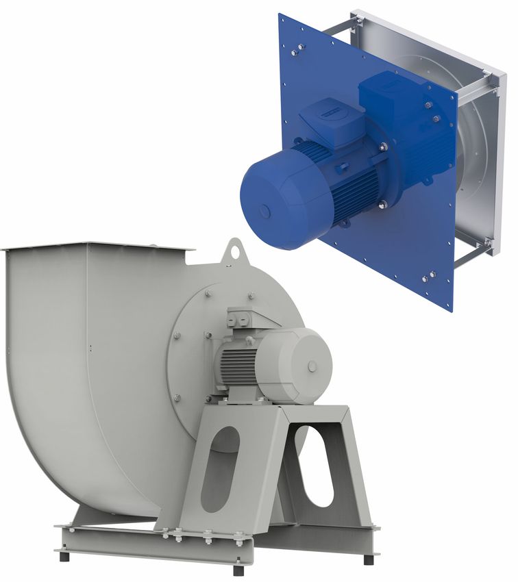
4.2.2 Optimal installation clearances
A
LD
A
ØL
ØDSa
B
L-KL-1766-1
• Impeller blade external-diameter : Ø DSa
• Distance on suction side: LA ≥ 0.5 x DSa *
• Distance on the pressure side: LD PRdry ≥ 1 x DSa
• Housing wall distances: A = 1.8 x DSa (A = B)
* In the case of disturbance flow (per example curved pipe at the suction side, flaps etc.) LA ≥ 1 x DSa
4.3 Mounting PL...
Attention!
Whenever working on a fan, under no circumstances loosen the bolts that hold the impeller to
the hub! Impeller and hub together form a balanced module which may only be removed and fitted as
a complete unit. Loosening these bolts can lead to imbalance and therefore to vibrations, even if the
bolts are tightened correctly before restarting the fan!
The following applies for loosely delivered impellers: The drive unit must be selected so that the
bearings are not overloaded or underloaded and operation in the range of the bend-critical speed can
be ruled out. The impellers are delivered pre-balanced. However, the total balance quality can change
in connection with the drive motor or the drive shaft. After mounting or remounting the impeller, the
balance quality of the assembled rotor (impeller mounted on drive motor or drive shaft) must be
checked and corrected if necessary before commissioning.
The drive unit must be selected so that the bearings are not overloaded or underloaded and operation
in the range of the bend-critical speed can be ruled out.
L-BAL-031-GB 2022/08 Index 015 Part.-No. 00292347-GB
11/42Assembly instructions Process air centrifugal fans Mounting
• Impellers with fixed hub,
– The impeller is connected to the shaft end of the drive motor using a fixed hub.
– Disassembly: Bend back the guard plate strap (5), loosen the axial threadlocker and pull off the
impeller with the hub using a suitable extractor (in case of heavy weight, secure with lifting
tackle). In some variants: remove the compensation washer between the hub and the shaft
shoulder (7). Keep all parts in a safe place.
– Mounting/installation: Clean and slightly grease all bare surfaces (shaft end, centre hole). In
some variants: put the compensation washer (7) removed during disassembly onto the shaft and
push it to the limit on the shaft shoulder. Pull the impeller with the hub (1) up to the shaft shoulder
(2) or the compensation washer (7) (transition fit). Secure with lifting tackle for heavy weights.
– Shaft retainer: Secure the axial shaft retainer with bolt (3) and washer (4) to the lockwasher
DIN 432 (5) and tightening pin (6). Maintain the tightening torque in accordance with the table.
Push up the lockwasher tab (5) so that it lies on a flank of the bolt head (3) to secure the bolt
against twisting or loosening.
Tightening torques for screw connections in Nm
Property class M5 M6 M8 M10 M12 M16 M20 M24
8.8 (Steel) 5.5 9.5 23 46 79 195 390 670
A4-80 (Stainless 4.9 8.5 20.4 41 70 167 326 714
steel)
• Impellers with clamping bush hub:
– The impeller is fitted to the end of the motor shaft using bushings.
• Mounting: Clean and grease all bare surfaces (fitting surfaces of clamping sleeves and motor
shaft). Insert clamping sleeve (1) into the hub (2) and line up the holes as shown in the fig. (pg. 3).
Lightly oil and screw in the set screws (3) - do not tighten yet.
• Push the impeller with clamping sleeve (1) load-free (with lifting gear if the impeller is heavy) onto
the shaft, align in axial position and tighten the set screws (3) evenly, tighten with torque
according to the table. Fill empty bore holes with grease to prevent penetration by foreign bodies.
After an operating time of approx. 1 hour. Re-check the tightening torqueof the screwed
connection with the necessary torque.
• Removal: Loosen all set-screws (3), depending on the size of the bushing, unscrew one or two set-
screws completely, oil them and screw them into the removal holes (4). Pull on one or both set-
screws, until the bushing (1) comes free of the hub (2). The impeller can now be taken off.
L-BAL-031-GB 2022/08 Index 015 Part.-No. 00292347-GB
12/42Assembly instructions Process air centrifugal fans Mounting
3 mounting holes, 4 removal holes
*1 1008 1108 1210 1610 1615 2012 2517 3020 3030 3525 3535 4030 4040 4535 4545 5040 5050
*2 5.6 5.6 20 20 20 30 50 90 90 115 115 170 170 190 190 270 270
*1 clamping sleeve, *2 tightening torque in Nm
4.4 PRdry dismounting (insulated design)
Step Operation
1 Release the screw connection (1), (2), (3)
2 Release the motor bolts (4)
3 Remove the impeller with hub (7) from the motor shaft with a suitable puller
4 Release the cooling fin bolts (6)
5 Pull out impeller with hub (7).
L-BAL-031-GB 2022/08 Index 015 Part.-No. 00292347-GB
13/42Assembly instructions Process air centrifugal fans Mounting
4.5 PR-T and PRdry dismounting (uninsulated design) with flange-mounted motor
Step Operation
1 Release (11) bolts and dismount motor/impeller unit (2) (only PR-T: take out of the housing (3))
Only PRdry with built-on jet plate (4): also release the spar (10) bolts and dismount the jet plate (4)
with spars (5)
2 Release the hub screw connection (12) and pull off the impeller with hub (6)
3 Release the motor screwed connection (13) and remove the motor (1)
For some variants: Remove the shaft gap washer (14).
To mount the impeller, proceed as in the chapter "Mounting PL...". For some variants: before mounting
the impeller, fasten the shaft gap washer (14) to with the motor bolting. While doing so, centre the
shaft gap washer so that a uniform gap to the impeller hub is continuously maintained!
L-BAL-031-GB 2022/08 Index 015 Part.-No. 00292347-GB
14/42Assembly instructions Process air centrifugal fans Mounting
4.6 Disassembly of PR-T, PRdry (non-insulated version) and PRdry (ER module) with foot
motor
Step Operation
1 PR-T only: release cover bolts (11) and housing bolts (14) on both sides
2 Only PR-T: in versions with split housing: Take off removable housing parts. Fit cross members to
stabilise the individual housing parts if necessary.
3 PR-T only: Lift the housing (3) carefully away from the impeller (6) and separate it from the fan
4 Only PRdry with built-on jet plate (4): also release the spar (10) bolts and dismount the jet plate (4)
with spars (5)
5 PRdry (ER module) only: Loosen the nozzle tray screw fitting (37) and carefully lift the nozzle tray (36)
over the impeller (6) and disconnect from the fan
6 Release the hub screw connection (12) and pull off the impeller with hub (6)
7 Release the motor screwed connection (13) and remove the motor (1)
To mount the impeller, proceed as in the chapter "Mounting the PL...". For some variants: Before
mounting the impeller, loosen the bolted connection (15) of the shaft gap washer (14); centre the shaft
gap washer so that a uniform gap to the impeller hub is continuously maintained and re-tighten the
bolted connection (15)!
L-BAL-031-GB 2022/08 Index 015 Part.-No. 00292347-GB
15/42Assembly instructions Process air centrifugal fans Mounting
4.7 Disassembly of PR-T with block bearing and foot motor
Step Operation
1 Release cover bolts (11) and housing bolts (14) on both sides
2 In versions with split housing: Take off removable housing parts. Fit cross members to stabilise the
individual housing parts if necessary.
3 Lift the housing (3) carefully away from the impeller and separate it from the fan
4 Secure the impeller with a suitable lifting device, loosen the hub locking screw (chapter 4.3 item 3) and
pull off the impeller and hub
5 Remove the coupling protection (22)
6 Remove the coupling according to manufacturer's specifications
7 Release the motor screwed connection (13) and remove the motor (1)
8 Release the bearing bolts (24) and remove the bearing (23)
9 Remove the shaft separating disc (14) or remove bearing according to chapter 4.15
" To mount the impeller, proceed as in the chapter "Mounting the PL...". For some variants: Before
mounting the impeller, loosen the bolted connection (15) of the shaft gap washer (14); centre the
shaft gap washer so that a uniform gap to the impeller hub is continuously maintained and re-
tighten the bolted connection (15)!
" Align the ball bearing (24) during assembly and securely attach to the bearing block.
L-BAL-031-GB 2022/08 Index 015 Part.-No. 00292347-GB
16/42Assembly instructions Process air centrifugal fans Mounting
4.8 Dismantling of PRdry ZAmovevent (roll out)
Step
1 Loosen screw fitting (11)
2 Loosen screw fitting on base frame (17)
3 Loosen safety screw (12) for roller plates
4 Evenly lower wheels by tightening screws (16), while carefully raising motor/impeller unit (2)
5 Carefully slide motor/impeller unit (2) out of housing using wheels
6 Remove screw fitting for space bars (10) and nozzle plate (4) with spacer bars (5)
7 Secure the impeller with a suitable lifting device, loosen the hub locking screw (chapter 4.3 item 3)
and pull off the impeller and hub
8 Release the motor screwed connection (13) and remove the motor (1)
9 On some versions: Remove shaft separating disc (14) or remove bearing as described in chapter 4.15
To mount the impeller, proceed as in the chapter "Mounting the PL...". For some variants: Before
mounting the impeller, loosen the bolted connection (15) of the shaft gap washer (14); centre the shaft
gap washer so that a uniform gap to the impeller hub is continuously maintained and re-tighten the
bolted connection (15)!
L-BAL-031-GB 2022/08 Index 015 Part.-No. 00292347-GB
17/42Assembly instructions Process air centrifugal fans Mounting
4.9 Dismantling of PR-T ZAmovevent (roll out)
Step
1 Loosen screw fitting on base frame (17)
2 Loosen safety screw (12) for roller plates
3 Evenly lower wheels by tightening screws (16), while carefully raising motor/impeller unit (2)
4 Carefully slide motor/impeller unit (2) out of housing
5 Loosen cover screw fitting (11) and housing screw fitting (29)
6 Remove inlet nozzle (30)
7 In versions with split housing: Take off removable housing parts. Fit cross members to stabilise the
individual housing parts if necessary.
8 Release the motor screwed connection (13) and remove the motor (1)
9 On some versions: Remove shaft separating disc (14) or remove bearing as described in chapter 4.15
To mount the impeller, proceed as in the chapter "Mounting the PL...". For some variants: Before
mounting the impeller, loosen the bolted connection (15) of the shaft gap washer (14); centre the shaft
gap washer so that a uniform gap to the impeller hub is continuously maintained and re-tighten the
bolted connection (15)!
L-BAL-031-GB 2022/08 Index 015 Part.-No. 00292347-GB
18/42Assembly instructions Process air centrifugal fans Mounting
4.10 Dismantling of belt driven PR-T
Step
1 Remove belt guard (18)
2 Loosen motor screw fitting (13) and tensioning spindles (25)
3 Remove pulleys (26 and 27) and belt (28)
4 Disassemble motor (1)
5 Loosen cover screw fitting (11) and housing screw fitting (29)
6 In versions with split housing: Take off removable housing parts. Fit cross members to stabilise the
individual housing parts if necessary
7 Remove inlet nozzle (30)
8 Lift the housing (3) carefully away from the impeller and separate it from the fan
9 Secure the impeller with a suitable lifting device, loosen the hub locking screw (chapter 4.3 item 3)
and pull off the impeller and hub
10 Release the bearing bolts (24) and remove the bearing (23)
11 On some versions: Remove shaft separating disc (14) or remove bearing as described in chapter 4.15
12 In the case of multi-row belt drives, always replace the belts in sets.
" To mount the impeller, proceed as in the chapter "Mounting the PL...". For some variants: Before
mounting the impeller, loosen the bolted connection (15) of the shaft gap washer (14); centre the
shaft gap washer so that a uniform gap to the impeller hub is continuously maintained and re-
tighten the bolted connection (15)!
" To fit the belt, follow the instructions in section 4.2.1 Belt drive.
" Align the ball bearing (24) during assembly and securely attach to the bearing block.
L-BAL-031-GB 2022/08 Index 015 Part.-No. 00292347-GB
19/42Assembly instructions Process air centrifugal fans Mounting
4.11 Dismantling of belt driven PRdry
Step
1 Remove belt guard (18)
2 Loosen motor screw fitting (13), clamping screws (29) and tensioning spindles (25)
3 Remove pulleys (26 and 27) and belt (28)
4 Disassemble motor (1)
5 Remove screw fitting for space bars (10) and nozzle plate (4) with spacer bars (5)
6 Secure the impeller with a suitable lifting device, loosen the hub locking screw (chapter 4.3 item 3)
and pull off the impeller and hub
7 Release the bearing bolts (24) and remove the bearing (23)
8 On some versions: Remove shaft separating disc (14) or remove bearing as described in chapter 4.15
9 In the case of multi-row belt drives, always replace the belts in sets.
" To mount the impeller, proceed as in the chapter "Mounting the PL...". For some variants: Before
mounting the impeller, loosen the bolted connection (15) of the shaft gap washer (14); centre the
shaft gap washer so that a uniform gap to the impeller hub is continuously maintained and re-
tighten the bolted connection (15)!
" To fit the belt, follow the instructions in section 4.2.1 Belt drive.
" Align the ball bearing (24) during assembly and securely attach to the bearing block.
L-BAL-031-GB 2022/08 Index 015 Part.-No. 00292347-GB
20/42Assembly instructions Process air centrifugal fans Mounting
4.12 Dismantling the PR-T swingout
Step
1 Relieve the damper with a suitable lifting device (31)
2 Loosen the screw fittings (11) and swing out the motor block/impeller unit (2)
3 Secure the impeller with a suitable lifting device, loosen the hub locking screw (chapter 4.3 item 3)
and pull off the impeller and hub
4 Release the motor screwed connection (13) and remove the motor (1)
5 Loosen the hinges (32) and remove the motor block unit (2)
6 On some versions: Remove shaft separating disc or remove bearing as described in chapter 4.16
7 Remove inlet nozzle (30)
8 In versions with split housing: Take off removable housing parts. Fit cross members to stabilise the
individual housing parts if necessary.
9 On some versions: Loosen the damper fitting (33) and remove the base frame (34) and counterframe
(35)
To mount the impeller, proceed as in the chapter "Mounting the PL...". For some variants: Before
mounting the impeller, loosen the bolted connection (15) of the shaft gap washer (14); centre the shaft
gap washer so that a uniform gap to the impeller hub is continuously maintained and re-tighten the
bolted connection (15)!
L-BAL-031-GB 2022/08 Index 015 Part.-No. 00292347-GB
21/42Assembly instructions Process air centrifugal fans Mounting
4.13 Dismounting and mounting the cooling disk (some versions)
In some versions of the fan a cooling disk is used, which is mounted using a shrunk force-fit directly
on the motor shaft (between end cap and impeller hub). This is to be dismounted and mounted in
accordance with the following instructions:
Dismounting the cooling disk Mounting the cooling disk
The cooling disk is shrunk with a force-fit on the The cooling disk must be preheated before mount-
motor shaft and can only be released after warming: ing, because it is a shrunk force-fit:
Step Activity Step Activity
1 Remove the motor (1) from the fan and 1 Stand the motor (1) in a vertical position
place it in the vertical position (shaft up- (shaft upwards).
wards).
2 Remove the key (3) from the groove in the 2 Hold the edge of the cooling disk (2) with
shaft and keep it for mounting later. a pair of pliers and heat it evenly to a
temperature of approx. 130 °C - 150 °C
(e.g. with a hot air blower or a gas burner).
Caution, hot surfaces - handle the cooling
disk only with a tool!
3 Heat the cooling disk (2) evenly to a tem- 3 Push the cooling disk on to the motor
perature of approx. 130 °C - 150 °C (e.g. shaft,at the same time with the flat side
with a hot air blower or gas burner); while facing the end cap and the conical side
doing this, heat only the disk - do not point facing the end of the shaft; the cooling
the jet of hot gas directly at the motor disk must be heated to the point where it
shaft! can be pushed over the shaft easily and
with play. Do not use force - if necessary,
continue heating!
L-BAL-031-GB 2022/08 Index 015 Part.-No. 00292347-GB
22/42Assembly instructions Process air centrifugal fans Mounting
Dismounting the cooling disk Mounting the cooling disk
4 Place flat levers or screwdrivers (4) at two 4 Push the cooling disk up to the shoulder
opposite positions under the edge of the on the motor shaft and allow to cool; only
cooling disk and push their ends down- move or mount the motor if the cooling
wards so that the cooling disk is raised up disk is seated firmly on the shaft.
in the direction of the shaft end, as soon
as the shrunk seating has released. Do
not use force - if necessary, continue heat-
ing.
5 Grip the edge of the cooling disk with pli- 5 Before mounting the motor, insert the key
ers and lift off the motor shaft. Caution, (3) into the groove on the shaft.
hot surfaces - handle the cooling disk only Mount the impeller (see chapter 4.3) then
with a tool! check the balance quality
Removing the cooling disc may damage it. When re-assembling, it should be replaced with a new
cooling disc.
4.14 Disassembling and mounting cooling wing
Attention!
If the fan was delivered with a cooling wing, operation without cooling wing is not admissible!
Operation without cooling wing can lead to overheating of the drive unit.
The cooling wing can be removed by loosing the screwed connection of the two halves of the cooling
wing from the shaft.
For mounting, the two halves of the cooling wing are screwed back together in the appropriate position
on the shaft. The balance quality of the fan must be checked after mounting the cooling wing.
4.15 Disassembly and mounting of the coupling
Attention!
Never operate the fan with misaligned shafts!
Operation with misaligned shafts can cause severe damage to the fan! The alignment of the shafts
must be checked every time the screws connection of the motor (13) or the bearing (24) is released.
4.15.1 Replacement of elastic elements
On most shafts, there is no need to remove the shafts to replace the elastic elements of the coupling.
Observe the coupling manufacturer’s instructions. If it should be necessary to disassemble the shaft,
proceed according to chapter 4.15.2 and 4.15.3.
4.15.2 Disassembling the coupling
L-BAL-031-GB 2022/08 Index 015 Part.-No. 00292347-GB
23/42Assembly instructions Process air centrifugal fans Mounting
Step
1 Remove the coupling protection (22)
2 Release the screwed connections of the coupling (26) and separate the coupling halves according to
the coupling manufacturer's instructions
3 Release the motor screwed connection (13) and remove the motor (1)
4 The coupling halves can then be removed from the shaft ends.
4.15.3 Assembling the coupling
Step Operation
1 Pull the coupling halves onto the shaft ends of the bearing (23) and the motor (1)
2 Mount the motor (1)
3 Assemble the coupling halves according to the coupling manufacturer's instructions
4 Align the shaft ends of the bearing (23) and the motor (1) to each other. See the coupling manufactur-
er's information for limit values for horizontal offset, vertical offset as well as angle offset.
5 The set screws (25) serve to align the motor and may not touch the motor base during operation.
6 Mount the coupling protection (22)
4.16 Disassembling and mounting compensator
The compensator can be designed with an earthing cable (30) to avoid electrostatic charging. To
relieve the load on the elastic fabric (29) support sleeves (31) are used at high pressures.
4.16.1 Disassembly of the compensator
Step Operation
1 Release the screwed connection (32) of the duct-side clamping flange
2 Remove the support sleeve (31)
3 Release the fan-side screwed connection (32) of the clamping flange
L-BAL-031-GB 2022/08 Index 015 Part.-No. 00292347-GB
24/42Assembly instructions Process air centrifugal fans Mounting
4.16.2 Mounting the compensator
Step Operation
1 Mount fan-side clamping flange (28) with elastic fabric (29) and earthing cable (30) with screwed
connection (32)
2 Insert the support sleeve (31)
3 Mount duct-side clamping flange (28) with elastic fabric (29) and earthing cable (30) with screwed
connection (32)
Attention!
Compensator may not be installed under tension or with offset.
The screwed connections of the clamping flange must be fitted so that the screw heads are on the
side of the elastic fabric.
4.17 Disassembling and mounting shaft seals
4.17.1 Disassembling and mounting shaft seal with lip seal
Sealing systems for shaft sealing can be equipped with one or more sealing lips. In sealing systems
with two or more sealing rings, additional measures to reduce leakage such as inert gas blanketing or
extraction can be taken.
The sealing elements (lip seal, static seal and housing) are pressed into a seal housing and can
be secured against slipping out by screwed connections.
To prevent large leakages, sealing lips must be aligned exactly to the shaft and the shaft must have
only very slight radial run-out deviations. See the instructions of the sealing element manufacturer for
the maximum admissible run-out deviation and centre deviation.
After changing the sealing element or the opposite face, lip seals must be run in for at least one hour.
There may be higher leakages and temperatures in the area of the seal in this run-in phase.
Disassembly in series PRdry with flange motor
Step Operation
1 Remove lines for inert gas or extraction
2 Release the screwed connection of the spacer members (chapter 4.5 item 10) and remove the inlet
nozzle with the nozzle tray
3 Release hub locking screw (chapter 4.5 item 12) and pull off impeller with hub.
4 Release motor screwed connection (chapter 4.5 item 13) and remove motor (chapter 4.5 item 1).
5 Release screwed connection (16) of the seal housing on the support plate and remove seal housing
(17)
6 Release locking screws on the seal housing and pull sealing elements (19) out of the seal housing
(17)
L-BAL-031-GB 2022/08 Index 015 Part.-No. 00292347-GB
25/42Assembly instructions Process air centrifugal fans Mounting
Mounting in series PRdry with flange motor
Step Operation
1 Check sealing elements and opposite face for wear. Opposite face must observe the limit values of
the admissible run-out deviation on the drive motor and may not have any score marks. Sealing lips
are worn when the end of the sealing lip tapers to a point or shows other signs of damage.
2 Press the sealing elements (2) into the seal housing and fit the locking screws (20)
3 Insert O-ring (18) or flat seal into the seal housing (17) and place the seal housing on the support plate
(2) and fix with screwed connection (16).
4 Mount motor (1) and align motor shaft to seal so that the maximum admissible centre deviation is not
exceeded.
5 Pull the impeller with hub onto the motor shaft and fix as described in chapter 4.3
6 Screw spacer members with nozzle tray and nozzle onto the support plate (chapter 4.5 item 10) and
align the inlet nozzle
7 Connect line for inert gas or extraction
Disassembly in series PR-T with flange motor
Step Operation
1 Remove lines for inert gas or extraction.
2 Release the screwed connections between support plate and housing (chapter 4.5 item 11) and
remove the motor/impeller unit from the housing
3 Release hub locking screw (chapter 4.5 item 12) and pull off impeller with hub.
4 Release motor screwed connection (chapter 4.5 item 13) and remove motor (chapter 4.5 item 1).
5 Release screwed connection of the seal housing on the support plate and remove seal housing (17)
6 Release locking screws (20) on the seal housing and pull sealing elements (19) out of the seal housing
(17)
Mounting in series PR-T with flange motor
Step Operation
1 Check sealing elements and opposite face for wear. Opposite face must observe the limit values of
the admissible run-out deviation on the drive motor and may not have any score marks. Sealing lips
are worn when the end of the sealing lip tapers to a point or shows other signs of damage.
2 Press the sealing elements (19) into the seal housing and fit the locking screws (20)
3 Insert O-rings (3), (4) or flat seal into the seal housing and place the seal housing on the support plate
and fix with screwed connection.
4 Mount motor and align motor shaft to seal so that the maximum admissible centre deviation is not
exceeded.
5 Pull the impeller with hub onto the motor shaft and fix as described in chapter 4.3
6 Install motor/impeller unit into the housing, align to the inlet nozzle and tighten screwed connections
between support plate and housing (chapter 4.5 item, 11)
7 Connect line for inert gas or extraction
L-BAL-031-GB 2022/08 Index 015 Part.-No. 00292347-GB
26/42Assembly instructions Process air centrifugal fans Mounting
Disassembly in series PRdry with foot motor
Step Operation
1 Remove lines for inert gas or extraction.
2 Release the screwed connections of the spacer members (chapter 4.6 item 10) and remove the inlet
nozzle with the nozzle tray.
3 Release hub locking screw (chapter 4.6 item 12) and pull off impeller with hub.
4 Release motor screwed connection (chapter 4.6 item 13) and remove motor (chapter 4.6 item 1).
5 Release screwed connection (16) of the seal housing on the support plate and remove seal housing
(17)
6 Release locking screws (20) on the seal housing and pull sealing elements (19) out of the seal housing
(17)
Mounting in series PRdry with foot motor
Step Operation
1 Check sealing elements (19) and opposite face (21) for wear. Opposite face (21) must observe the
limit values of the admissible run-out deviation on the drive motor and may not have any score marks.
Sealing lips are worn when the end of the sealing lip tapers to a point or shows other signs of damage.
2 Press the sealing elements (19) into the seal housing and fit the locking screws (20)
3 Insert O-ring (18) or flat seal into the seal housing (17) and place the seal housing on the support plate
(2) and fix with screwed connection (16).
4 Mount motor and align motor shaft to seal so that the maximum admissible centre deviation is not
exceeded.
5 Pull the impeller with hub onto the motor shaft and fix as described in chapter 4.3
6 Screw spacer members with nozzle tray and nozzle onto the support plate and align the inlet nozzle
7 Connect line for inert gas or extraction
Disassembly in series PR-T with foot motor
Step Operation
1 Remove lines for inert gas or extraction
2 Release the screwed connections between support plate and housing (chapter 4.6 item 11) and
remove the motor/impeller unit from the housing
3 Release hub locking screw (chapter 4.6 item 12) and pull off impeller with hub.
4 Release motor screwed connection (chapter 4.6 item 13) and remove motor (chapter 4.6 item 1).
5 Release screwed connection of the seal housing on the support plate and remove seal housing (17)
6 Release locking screws on the seal housing and pull sealing elements (19) out of the seal housing
(17)
L-BAL-031-GB 2022/08 Index 015 Part.-No. 00292347-GB
27/42Assembly instructions Process air centrifugal fans Mounting
Mounting in series PR-T with foot motor
Step Operation
1 Check sealing elements and opposite face (21) for wear. Opposite face must observe the limit values
of the admissible run-out deviation on the drive motor and may not have any score marks. Sealing lips
are worn when the end of the sealing lip tapers to a point or shows other signs of damage.
2 Press the sealing elements (19) into the seal housing (17) and fit the locking screws (20)
3 Insert O-ring (18) or flat seal into the seal housing and place the seal housing on the support plate and
fix with screwed connection (16).
4 Mount motor and align motor shaft to seal so that the maximum admissible centre deviation is not
exceeded.
5 Pull the impeller with hub onto the motor shaft and fix as described in chapter 4.3
6 Install motor/impeller unit into the housing, align to the inlet nozzle and tighten screwed connections
between support plate and housing (chapter 4.6 item, 11)
7 Connect line for inert gas or extraction
4.17.2 Disassembling and mounting shaft seal with floating ring seals
• Floating ring seals with seal housing divided in axis direction can be changed without removing the
impeller. Observe the seal manufacturer’s instructions.
• Floating ring seals with seal housing divided vertically to the axis are disassembled similarly to
sealing elements with lip seal. Proceed as described in 4.17.1 to disassemble the seal housing and
then follow the instructions of the seal manufacturer. Mounting takes place according to the seal
manufacturer's instructions and as described in 4.17.1 from mounting of the seal housing.
4.18 Assembly in a humid atmosphere
Info
If the device is not in use for longer periods in a humid atmosphere, it is recommended to operate the
motor/fan for at least 2 hours every month at 80-100 % of maximum speed to remove any moisture
that has penetrated inside.
4.19 Connection of pipes
• Tensions on the fan by pipe connections must be avoided. These can lead to contact between
rotating and stationary parts.
• Suction and pressure side connections of pipes must be sealed.
• No vibrations, impacts or loads may be transferred to the fan from the pipes.
• Pay attention to thermal expansion of the fan and ducts
• The fan may only be fixed to the suction side flange or pressure side frame if this is expressly
agreed in the contract.
• Suction and pressure side ducts must be designed so that an even inflow and outflow is possible.
L-BAL-031-GB 2022/08 Index 015 Part.-No. 00292347-GB
28/42You can also read