Radar Imager for Mars' subsurFAce eXperiment (RIMFAX) - PDS Geosciences Node
←
→
Page content transcription
If your browser does not render page correctly, please read the page content below
Mars 2020
Radar Imager for Mars’ subsurFAce eXperiment (RIMFAX)

 PDS Archive
 Calibrated Data Record (CDR)
 Software Interface Specification

 Rev. 0.7
 July 22, 2021
 Addressing Review Liens

 Prepared by
 Patrick Russell, Mark Sullivan
 patrick.russell@epss.ucla.edu, marks@mars.ucla.edu

M2020 RIMFAX Calibrated Data Record SIS July 22, 2021

 Mars 2020
 Radar Imager for Mars’ subsurFAce eXperiment (RIMFAX)

 PDS Archive
 Calibrated Data Record (CDR)
 Software Interface Specification

Custodian:

 Mark Sullivan Date
 RIMFAX Archivist

Approved:

 Svein-Erik Hamran Date
 RIMFAX Principal Investigator

 Susan Slavney Date
 PDS Geosciences Node Representative
M2020 RIMFAX Calibrated Data Record SIS July 22, 2021

Contents
Introduction 1
 Document Change Log 1
 TBD Items 1
 Abbreviations 1
 Glossary 3
Overview 4
 Purpose and Scope 5
 Contents 5
 Applicable Documents 5
 Audience 6
 Mars 2020 Mission 6
 RIMFAX Instrument Description 7
 Instrument Operation 7
 Surface Operation 11
RIMFAX Data Products 12
 Data Products Overview 12
 Data Processing 13
 Data Processing Levels 13
 Nominal Data Processing 14
 Processing Differences by Measurement Type 16
 Position Determination 16
 Data Flow 17
 Standards Used in Generating Data Products 17
 Time Standards 17
 Coordinate Systems 18
 Data Storage Conventions 21
 Applicable Software 21
 Backups and Duplicates 21
RIMFAX Archive Organization, Identifiers and Naming Conventions 21
 Archive Structure 21
 Logical Identifiers 21
M2020 RIMFAX Calibrated Data Record SIS July 22, 2021

 LID Formation 22
 VID Formation 22
 RIMFAX Bundle 23
 RIMFAX Collections 23
 RIMFAX Calibrated Data Products 23
 RIMFAX Calibrated Data Product File Naming Conventions 24
RIMFAX Product Formats 24
 Data Product Formats 24
 Raw Data File Structure 24
 Calibrated Data File Structure 24
 Browse Product Formats 26
 Document Product Formats 26
 PDS Labels 27
Calibrated Data Product Parameters 28
CDR Catalog Columns 35
Support Staff and Cognizant Persons 36
M2020 RIMFAX Calibrated Data Record SIS July 22, 2021

List of Tables
Table 1: Document change log. 1
Table 2: List of TBD items. 1
Table 3: Abbreviations and their meanings. 1
Table 4: RIMFAX instrumented range (in free space) as a function of bandwidth and sweep time.
Data volume per sounding given for each sweep time. 12
Table 5: Data processing level definitions. 13
Table 6: Coordinate frames relevant to RIMFAX location, data, and operations. 18
Table 7: Translational offsets defining the RIMFAX Antenna Frame (RAF) with respect to the
Rover Mechanical frame (RMECH) and the Rover Navigational frame (RNAV). Individual
frame-to-frame as well as net RAF-RNAV offsets are given. There are no rotational offsets
among these coordinate frames. * Antenna feed point (AFP) - RNAV offset is ~744 mm. 20
Table 8: The RIMFAX Bundle. 23
Table 9: Collections in the RIMFAX Bundle. 23
Table 10: Example of data product LID in the RIMFAX calibrated data collection. 23
Table 11: Fundamentally different types of records in the RIMFAX CDR data product data table,
as identified by the data-table parameter “record_type” (in the first column of each data-table
record). 24
Table A1: Complete list of parameters recorded in the ASCII-text data table that makes up the
CSV-format RIMFAX CDR data product. 28
Table A2: Comments for respective rows in Table A1, as cross-referenced by the value of the
“Comment Reference Label” field in each table. 33
Table B1. Partial list of column-headings in the CDR Catalog file. 35
Table C1: Archive support staff. 36
M2020 RIMFAX Calibrated Data Record SIS July 22, 2021

1 Introduction
This software interface specification (SIS) describes the content, generation, and format of the
Planetary Data System (PDS) archive containing the Calibrated data from the RIMFAX
instrument on the M2020 Perseverance rover mission.

1.1 Document Change Log
Table 1: Document change log.
 Version Change Date Affected portion
 0.1 Initial draft November 14, 2020 All
 0.2 Edited draft January 21, 2021 All
 0.3 Submitted for Review February 17, 2021 All
 0.4 Re-Submitted for Review March 23, 2021 All
 0.6 Addressing Review Liens June 24, 2021 Responses to Reviewers,
 Appendices, scattered
 elsewhere
 0.7 Addressing Review Liens July 22, 2021 Responses to Reviewers,
 Appendices, scattered
 elsewhere

1.2 TBD Items
Table 2 lists items that are not yet finalized.
Table 2: List of TBD items.
 Item Section(s) Page(s)

1.3 Abbreviations
Table 3: Abbreviations and their meanings.
 Abbreviation Meaning
ASCII American Standard Code for Information Interchange
CDR Calibrated Data Record
CSV Comma Separated Value
EDR Experiment Data Record
FFI Forsvarets Forskningsinstitutt (Norwegian Defense Research Establishment)
FM Frame Manager
FMCW Frequency Modulated Continuous Wave
FTP File Transfer Protocol

 1
M2020 RIMFAX Calibrated Data Record SIS July 22, 2021

GDS Ground Data Systems
GEO PDS Geosciences Node (Washington University, St. Louis, Missouri)
GPR Ground Penetrating Radar
HK Housekeeping
HTML Hypertext Markup Language
ICD Interface Control Document
IDS Instrument Data System
IFFT Inverse Fast Fourier Transform
ISO International Standards Organization
JPL Jet Propulsion Laboratory (Pasadena, CA)
LID Logical Identifier
LIDVID Versioned Logical Identifier
LIS Long Integration Sounding
M2020 Mars 2020
MMRTG Multi-Mission Radioisotope Thermoelectric Generator
NAIF Navigation and Ancillary Information Facility (JPL)
NASA National Aeronautics and Space Administration
NSSDCA National Space Science Data Coordinated Archive (Goddard Space Flight Center)
PDS Planetary Data System
PDS4 Planetary Data System Version 4
RAF RIMFAX Antenna Frame
RCE Rover Compute Element
RIM RIMFAX Instrument Manager
RIMFAX Radar Imager for Mars’ subsurFAce eXperiment
RMECH Rover Mechanical Frame
RNAV Rover Navigation Frame
SAPP Surface Attitude, Position and Pointing
SIS Software Interface Specification
SPICE Spacecraft, Planet, Instrument, C-matrix, and Events (NAIF data format)
SPK Spacecraft and Planetary ephemeris Kernel (NAIF)
TBD To Be Determined
UCLA University of California, Los Angeles
URN Uniform Resource Name
UTC Universal Time Coordinated
VID Version Identifier
XML eXtensible Markup Language

 2
M2020 RIMFAX Calibrated Data Record SIS July 22, 2021

1.4 Glossary
Many of these definitions are taken from Appendix A of the PDS4 Concepts Document,
https://pds.nasa.gov/datastandards/about/ . The reader is referred to that document for more
information.
Archive – A place in which public records or historical documents are preserved; also the
material preserved – often used in plural. The term may be capitalized when referring to all of
PDS holdings – the PDS Archive.
Basic Product – The simplest product in PDS4; one or more data objects (and their description
objects), which constitute (typically) a single observation, document, etc. The only PDS4
products that are not basic products are collection and bundle products.
Bundle Product – A list of related collections. For example, a bundle could list a collection of
raw data obtained by an instrument during its mission lifetime, a collection of the calibration
products associated with the instrument, and a collection of all documentation relevant to the
first two collections.
Class – The set of attributes (including a name and identifier) which describes an item defined in
the PDS Information Model. A class is generic – a template from which individual items may be
constructed.
Collection Product – A list of closely related basic products of a single type (e.g. observational
data, browse, documents, etc.). A collection is itself a product (because it is simply a list, with its
label), but it is not a basic product.
Data Object – A generic term for an object that is described by a description object. Data
objects include both digital and non-digital objects.
Description Object – An object that describes another object. As appropriate, it will have
structural and descriptive components. In PDS4 a ‘description object’ is a digital object – a string
of bits with a predefined structure.
Digital Object – An object which consists of real electronically stored (digital) data.
Identifier – A unique character string by which a product, object, or other entity may be
identified and located. Identifiers can be global, in which case they are unique across all of PDS
(and its federation partners). A local identifier must be unique within a label.
Label – The aggregation of one or more description objects such that the aggregation describes a
single PDS product. In the PDS4 implementation, labels are constructed using XML.
Logical Identifier (LID) – An identifier which identifies the set of all versions of a product.
Versioned Logical Identifier (LIDVID) – The concatenation of a logical identifier with a
version identifier, providing a unique identifier for each version of product.
Manifest - A list of contents.

 3
M2020 RIMFAX Calibrated Data Record SIS July 22, 2021

Metadata – Data about data – for example, a ‘description object’ contains information
(metadata) about an ‘object.’
Object – A single instance of a class defined in the PDS Information Model.
PDS Information Model – The set of rules governing the structure and content of PDS
metadata. While the Information Model has been implemented in XML for PDS4, the model
itself is implementation independent.
Product – One or more tagged objects (digital, non-digital, or both) grouped together and having
a single PDS-unique identifier. In the PDS4 implementation, the descriptions are combined into a
single XML label. Although it may be possible to locate individual objects within PDS (and to
find specific bit strings within digital objects), PDS4 defines ‘products’ to be the smallest
granular unit of addressable data within its complete holdings.
Tagged Object – An entity categorized by the PDS Information Model, and described by a PDS
label.
Registry – A database that provides services for sharing content and metadata.
Repository – A place, room, or container where something is deposited or stored (often for
safety).
XML – eXtensible Markup Language.
XML schema – The definition of an XML document, specifying required and optional XML
elements, their order, and parent-child relationships.

 4
M2020 RIMFAX Calibrated Data Record SIS July 22, 2021

2 Overview
2.1 Purpose and Scope
This SIS covers the RIMFAX Calibrated Data Product. The purpose of this SIS document is to
provide users of the Calibrated data with: some instrument functionality and surface operations
background; the processing by which Calibrated data is generated from Raw data; a description
of Calibrated products; and the internal format and naming of Calibrated data product files. The
users for whom this document is intended are the scientists who will analyze the data, including
those associated with the project and those in the general planetary science community.

2.2 Contents
This SIS includes descriptions of how the RIMFAX instrument acquires measurements and
operates, how the data are processed and calibrated from Raw to calibrated forms, and how the
files are formatted, labeled, and uniquely identified. The document also discusses standards used
in generating the data products. It is the document’s goal that the data files, structure, and
organization be described in sufficient detail to enable a user to find, read, and understand the
data.
Appendices include: (A) a list of the parameters, and their definitions, included in the CDR data
table; (B) ; (C) a list of support staff and cognizant persons involved in generating the archive.

2.3 Applicable Documents
[1] Planetary Data System Standards Reference, version 1.16.0.0, April 21, 2021,
 https://pds.nasa.gov/datastandards/documents/sr/.
[2] PDS4 Common Data Dictionary, Abridged, version 1.16.0.0, April 21, 2021,
 https://pds.nasa.gov/datastandards/documents/dd/.
[3] PDS4 Information Model Specification, version 1.16.0.0, April 21, 2021,
 https://pds.nasa.gov/datastandards/documents/im/.
[4] PDS4 Concepts Document, version 1.16.0.0, April 21, 2021,
 https://pds.nasa.gov/datastandards/documents/concepts/.
[5] PDS4 Data Provider’s Handbook, version 1.16.0.0, April 21, 2021,
 https://pds.nasa.gov/datastandards/documents/dph/.
[6] Mars 2020 Archive Generation, Validation, and Transfer Plan, JPL D-95520.
[7] RIMFAX - PDS Node Interface Control Document (ICD).
[8] Mars 2020 Software Interface Specification (SIS): RIMFAX Experiment Data Record (EDR)
 Data Products, JPL D-99964.
[9] Mars 2020 Software Interface Specification (SIS): RIMFAX PDS Archive Bundle.
[10] Radar Imager for Mars’ Subsurface Experiment – RIMFAX, Svein-Erik Hamran, David
 A. Paige, Hans E. F. Amundsen, Tor Berger, Sverre Brovoll, Lynn Carter, Leif Damsgård,

 5
M2020 RIMFAX Calibrated Data Record SIS July 22, 2021

 Henning Dypvik, Jo Eide, Sigurd Eide, Rebecca Ghent, Øystein Helleren, Jack Kohler, Mike
 Mellon, Daniel C. Nunes, Dirk Plettemeier, Kathryn Rowe, Patrick Russell & Mats Jørgen
 Øyan, Space Science Reviews 216, Article Number 128 (2020)
 https://doi.org/10.1007/s11214-020-00740-4
[11] Mars 2020 Rover Attitude, Positioning and Pointing (RAPP) Functional Design
 Description (FDD) document, JPL D-95865, ID 64632, Owner: Farah Alibay, Last Modified:
 2020-05-27, Date: April 20, 2021.
This SIS is consistent with PDS4 Documents [1 - 6]. These documents are subject to periodic
revision. The most recent versions may be found at https://pds.nasa.gov/pds4. The PDS4
products specified in this SIS have been designed based on the versions current at the time,
which are those listed above.

2.4 Audience
This SIS is intended to be used by data users wishing to understand the format and content of the
RIMFAX Calibrated Data. Typically these individuals would include scientists, data analysts,
and software engineers, whether part of the project or part of the broader planetary science
community.

2.5 Mars 2020 Mission
The primary goals of the Mars 2020 Perseverance rover mission are to search for biosignatures,
or evidence of past life, and to return samples of martian geologic materials to Earth for analysis.
The suite of scientific instruments included on the rover is intended to interpret landing-site
geologic history, find and characterize habitable environments, and document textural,
mineralogical and organic biosignatures. The rover will also collect, store, and cache ~ 30
geologic samples and characterize their geologic and paleoenvironmental context.
The Mars 2020 mission was launched from Cape Canaveral, Florida, on July 30, 2020 and
landed on Mars on February 18, 2021. The landing site, in Jezero Crater, was chosen to optimize
chances of achieving the mission’s goals, and should elucidate Mars’ past in addition to local
history. Evidence collected from previous missions suggests the crater once contained a lake,
several billion years ago. Today, the most striking feature at the site is a well-preserved, layered
sequence of sediments exhibiting channel-like structures, interpreted as a delta. Surroundings
also show possible carbonate rocks, lacustrine sediments, silica-rich deposits, and volcanic
materials. All together, this represents an environment with high potential for former habitability,
biosignature preservation, and provision of a diverse suite of informative samples.
Perseverance will carry the first GPR on the surface of Mars, RIMFAX. Data from RIMFAX
will provide information on the structure and geophysical properties of the subsurface. Findings
will yield insight into stratigraphic relationships, links between separated outcrops, regolith and
bedrock densities, geologic context for samples, processes affecting biosignature preservation
over time, and rover strategic and tactical planning.

 6
M2020 RIMFAX Calibrated Data Record SIS July 22, 2021

2.6 RIMFAX Instrument Description
The RIMFAX instrument and science investigation are more fully described in the publication
“Radar Imager for Mars’ Subsurface Experiment – RIMFAX”, Svein-Erik Hamran, David A.
Paige, Hans E. F. Amundsen, Tor Berger, Sverre Brovoll, Lynn Carter, Leif Damsgård, Henning
Dypvik, Jo Eide, Sigurd Eide, Rebecca Ghent, Øystein Helleren, Jack Kohler, Mike Mellon,
Daniel C. Nunes, Dirk Plettemeier, Kathryn Rowe, Patrick Russell & Mats Jørgen Øyan, Space
Science Reviews 216, Article Number 128 (2020) https://doi.org/10.1007/s11214-020-00740-4
In this section, a brief overview of the RIMFAX instrument is provided to familiarize the reader
with the instrument’s primary functionality and operational implementation.
The principal goals of the RIMFAX investigation are to image the shallow subsurface structure
beneath the rover and provide information regarding subsurface composition. The data provided
by RIMFAX will aid the Mars2020 rover in its mission to explore the ancient habitability of its
field area and to select a set of promising samples for caching and eventual sample return.

2.6.1 Instrument Operation
RIMFAX is a ground penetrating radar (GPR) that uses a single antenna to transmit (Tx) and
receive (Rx) electromagnetic waves over a range of frequencies (150 to 1200 MHz) into/from the
subsurface. A principle block diagram of the instrument is given in Figure 1. The instrument can
be operated in either active (Tx and Rx) or passive (Rx-only) modes. Transmitted waves
propagate downward until they are reflected back by shallow (≤ 10s of m) subsurface interfaces
in geologic materials or structures, across which exist discontinuities in permittivity (the storage
of electrical energy in an electric field).

Figure 1: Principle block diagram of the RIMFAX instrument.
Each sweep across the radar’s frequency range, or bandwidth, produces a radar measurement
known as a “sounding”. A raw FMCW RIMFAX sounding is a record of the reflected power
returned at each frequency over the bandwidth. A processed RIMFAX sounding, more analogous

 7
M2020 RIMFAX Calibrated Data Record SIS July 22, 2021

to most terrestrial-use GPRs, is a time series of the reflected power. The receival time of each
sample is related to the position in the subsurface from which the received power was reflected.
The RIMFAX instrument paper [10] describes this relationship, which is largely modulated by
the velocity of the signal in the medium, in turn influenced by the material’s dielectric and
physical properties. As the rover (and RIMFAX) moves along its traverse path, successive
soundings are taken at fixed increments of distance along the surface. The 2-D display of these
soundings according to their acquisition location is an image known as a “radargram”, with
distance along the traverse increasing towards the right, and time (related to depth, as above),
increasing downwards. Measurements can also be made while the rover (and RIMFAX) is
stationary with respect to the surface, and successive co-located stationary soundings can build a
time series. Such a dataset may capture how the dielectric properties of the surface/subsurface at
that individual location may change over a given period (e.g., in response to thermal influences).
To properly convert the vertical dimension from the time delay, t, to depth, d, it is necessary to
apply values of permittivity, e, to the subsurface to correct for the speed of light in the medium as
follows:
 d = v * t,
where:
 v = c / sqrt(e).
Further, ancillary navigation data from the rover are necessary to determine the location of each
sounding.
Waveform
RIMFAX uses a Frequency Modulated Continuous Wave (FMCW) waveform. In FMCW radar
the baseband signal is low-pass filtered before being sampled. This filter effectively removes
deeper reflectors and yields an ambiguity-free range interval. The RIMFAX FMCW waveform
uses a gating technique that allows a single antenna to be used both as a transmitter and receiver.
The working principle of an FMCW radar is illustrated in Figure 2. A signal, Tx, is swept
through the full bandwidth, B, of frequencies (from f1 to f2) over the time span, Ts (from t1 to t2),
and is transmitted through the antenna (as represented by the solid line Tx). A signal reflected
from a distance, d, is received by the antenna delayed by the two-way travel time, t, equal to
2d/v, where v is the wave velocity in the material. This delayed received signal, Rx, has a
different frequency than the signal currently being transmitted (represented by the dashed line
Rx). Multiplying the received signal with the signal currently being transmitted gives a baseband
signal, Sb = Rx x Tx. At any point in time, this baseband signal has a frequency equal to the
frequency difference between the transmitted and received signals. For a stationary reflector this
frequency difference is constant over the sweep. The frequency of this constant baseband signal,
called the beat frequency, fb, is proportional to the delay time, t, and thereby to the distance
range, expressed as 2d/v, to the reflector. The proportionality constant is given by the ratio
between the sweep bandwidth and the duration of the sweep, or B/Ts. The frequency of the beat
signal is thus:

 8
M2020 RIMFAX Calibrated Data Record SIS July 22, 2021

 2
 =
 .

Measuring the beat frequency thus yields the range to the reflector. The amplitude of the received
sine-wave signal gives the reflection strength. If several reflectors are present the baseband
signal will be a summation of all the different reflected signals. Spectral estimation techniques
like Fourier transforms can calculate the reflected signal.

Figure 2: Illustration of RIMFAX signal generation, including beat frequency, fb, and baseband
signal amplitude, Sb.
Gating
The FMCW signal is gated in a switch before being amplified and fed to the antenna through the
antenna switch (Figure 1). The gating switches the FMCW signal on and off with a duty cycle up
to 50%. The gating frequency is much lower than the transmitted-signal frequency and higher
 9
M2020 RIMFAX Calibrated Data Record SIS July 22, 2021

than the baseband signal spectrum. The reflected signal response will be a convolution between
the gated, square-wave transmitted signal and the square wave of the receiver gating. This
response function will be a triangular waveform producing an effective linear gain on the
received signal as a function of depth. Typically the maximum of the gating function will
correspond to the maximum instrumented range. After the gating peak a linear reduction in
amplitude will be combined with the spherical loss and attenuation in the media reducing the
reflected signal rapidly.
If the receiver gating waveform is turned on with a slight delay after the transmitter gating signal
turns off, there will be a time window where no signal is entering the receiver. This is illustrated
in Figure 3, in which the receiver gate signal delay time is represented by . Any reflected
signal from the exterior or subsurface that arrives during the time-delay window from 0 to
does not enter the receiver. The radar response as a function of time will then be a symmetric
triangular shape with a flat-peaked top of time-length TR, giving a linear gain with travel time
and depth. If the frequency of the square wave gating signal is , then the total gating window
length in time is:

 = 1 / .

The gating makes it possible to remove strong reflectors from the receiver signal before the
signal is digitized, effectively increasing the dynamic range coverage of the radar system.

Figure 3: RIMFAX gating illustration. X-axis represents increasing time.
Calibration cable

 10
M2020 RIMFAX Calibrated Data Record SIS July 22, 2021

The RIMFAX electronics unit has two different outputs for transmitting the FMCW signal: an
antenna port, where the antenna is connected via the antenna cable running through the rover
bulkhead, and the calibration port, where a 2.8-m calibration cable is connected. The calibration
cable is placed close to the RIMFAX electronics, inside the rover, and is shorted at the end to
produce a reflection from the end of the cable. An electronic switch controls whether the
calibration cable or the antenna is used.
The main purpose of the calibration cable is to provide measurements of gain variations in the
transmitter and receiver. During operations on Mars the calibration cable measurements will be
performed at specific distances during a traverse, for example every 10 meters, or at specific
time intervals during stationary activities, for example every hour. The reflected signal from the
calibration cable termination will be used to calibrate for temperature-dependent variations in
radar amplitude and timing.

2.6.2 Surface Operation
RIMFAX is designed to operate in different modes in which radar parameters are set to optimize
data collection for different subsurface conditions and depths. The RIMFAX gating makes it
possible to omit the recording of close-range reflections, typically from the antenna and surface,
which would otherwise limit the dynamic range. The removal of these reflections makes it
possible, when desired, to increase the radar’s gain to capture weak subsurface reflections.
Shifting the receiver dynamic range window particularly to each mode effectively increases the
radar’s total dynamic range when soundings from different modes are considered together.
1. Surface Mode
 The antenna reflection is captured in the receiver window.
 Measures the surface reflection and the very upper subsurface only.
2. Shallow Mode
 The antenna reflection is removed from the receiver window.
 Measures the surface reflection and the shallow subsurface.
3. Deep Mode
 The antenna and surface reflections are removed from the receiver window.
 Measures reflections from the upper subsurface (~1 m depth) through the instrumented
 range.
Together, these modes extend the dynamic range of RIMFAX up to 62 dB above the dynamic
range of a single mode, giving an approximate total dynamic range of 160 dB. For stationary
measurements, the dynamic range can be further increased by doing a Long Integration Sounding
(LIS), in which a few to several hundred soundings are summed together (on the rover RCE) to
increase the processing gain.

 11
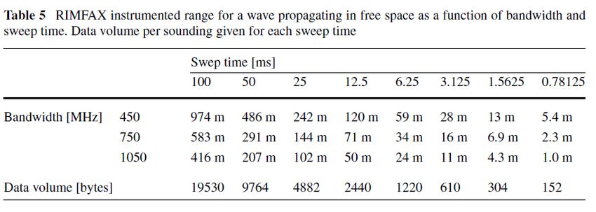
M2020 RIMFAX Calibrated Data Record SIS July 22, 2021

Instrumented range and resolution can also be selected within each mode to optimize
measurements based on subsurface composition and penetration depth. This is accomplished by
choosing combinations of frequency range (i.e.,bandwidth) and sweep time of the waveform
over the frequency range, which also results in different data volumes (Table 5).
Table 4: RIMFAX instrumented range (in free space) as a function of bandwidth and sweep time.
Data volume per sounding given for each sweep time.

Typically, a high resolution using the full bandwidth is selected in the shallow mode, when most
frequencies will be able to penetrate to the full, shallow instrumented range. In the deep mode, a
narrower bandwidth limited to the lower part of the frequency range is used, and there is a
tradeoff between data volume (based on number of samples per sounding) and penetration depth.
Choices of sweep time are limited to the 8 values in Table 5. Bandwidth can be set between 0
and 1050 MHz (i.e., not limited to values in Table 5) within the frequency range 150-1200 MHz.
For sweep times less than 100 ms, sweeps are repeated and signal is averaged until the total
collection time period reaches 100 ms. This practice ensures that the processing gain is equal for
each sounding, independent of radar configuration.
The nominal plan for operation on Mars is to collect soundings from each of three modes every
5-10 cm along the rover traverse, During a drive, the distance the antenna has moved is
determined and tracked solely by the FM, with no memory, modifications, or correction by
RIMFAX (Section 3.2.4). When the tactically planned interval distance (since the previous
measurement) has been attained as the rover moves along its path, the RIMFAX Instrument
Manager (RIM) on the Rover Computer Element (RCE) commands RIMFAX to make the
subsequent measurement.
In addition to nominal, active operation, RIMFAX can be operated in passive modes with the
transmitter off but the receiver on, connected to either the antenna or the calibration cable. An
ambient spectrum can be measured through the antenna, or an estimation of self-induced noise
can be made with the calibration cable and used as an input to signal processing to increase
system performance.

 12
M2020 RIMFAX Calibrated Data Record SIS July 22, 2021

3 RIMFAX Data Products
3.1 Data Products Overview
The primary RIMFAX CDR data product is a table containing RIMFAX measurement data. This
Calibrated data product contains a single, CSV-format file composed of a data table of ASCII
text fields. This table includes all processed radar data, housekeeping data, calibration arrays,
associated parameters, and a header row. One Calibrated data product is generated for each
M2020 Sol in which RIMFAX obtained measurements, and contains measurements from only
one Sol. There are no Calibrated data products from before landing. The radar data present in this
table has been processed as described in Section 3.2 into time-domain samples (equal time
increments), each containing the value of the ratio of the measured received signal to the radiated
signal. Each CSV file is accompanied by an eXtensible Markup Language (XML) format PDS4
label file (.xml). Details of the Calibrated product file structure are provided in Section 5.1.2,
while this Section 3 focuses on processing of the Raw data into the Calibrated data product.

3.2 Data Processing
This section describes the processing of RIMFAX Raw data to Calibrated data. The data is
calibrated to physical units, and these calibration steps and algorithms are described. The level of
processing incorporated in these Calibrated products was chosen with the aim of bringing the
RIMFAX radar data to a state at which it would likely most resemble a familiar starting point to
typical terrestrial GPR users. The individual algorithms and the processing as a whole is
designed such that these steps may be reversed to the state of the original data, with no
information lost.

3.2.1 Data Processing Levels
Data processing levels mentioned in this SIS refer to the PDS4 processing level described in
Table 4. The RIMFAX data products described in this SIS are PDS4 processing-level
“Calibrated”. The data has been calibrated to physical units and the products include positional
and geometric information on the RIMFAX antenna, the Perseverance rover, and the sun.
Table 5: Data processing level definitions.
 PDS4 CODMAC NASA
 processing PDS4 processing level description level (used level (used
 level in PDS3) in PDS3)
 Telemetry data with instrument data embedded. PDS
 n/a 1 0
 does not archive telemetry data.
 Original data from an instrument. If compression,
 reformatting, packetization, or other translation has
 Raw been applied to facilitate data transmission or storage, 2 1A
 those processes are reversed so that the archived data
 are in a PDS approved archive format.
 Partially Data that have been processed beyond the raw stage
 3 1A
 Processed but which have not yet reached calibrated status.

 13
M2020 RIMFAX Calibrated Data Record SIS July 22, 2021

 Data converted to physical units, which makes values
 Calibrated 4 1B
 independent of the instrument.
 Results that have been distilled from one or more
 calibrated data products (for example, maps, gravity
 or magnetic fields, or ring particle size distributions).
 Supplementary data, such as calibration tables or
 Derived 4+ 2+
 tables of viewing geometry, used to interpret
 observational data should also be classified as
 ‘derived’ data if not easily matched to one of the
 other three categories.

3.2.2 Nominal Data Processing
This section describes the processing applied to Raw data to result in Calibrated-level data
products, ie CDRs. The nominal case is considered to be active antenna soundings, made either
while the rover is stationary or moving along a traverse. The flow of data from JPL’s Instrument
Data System (IDS), through processing steps, and to PDS is shown in Figure 4.

 14
M2020 RIMFAX Calibrated Data Record SIS July 22, 2021

Figure 4. RIMFAX data and processing flow from IDS to PDS.
Raw sounding data contain RIMFAX science data in the frequency domain. Part of the
processing is done in the frequency domain. Eventually, RIMFAX science data is transformed to
time domain, undergoes further processing, and the resulting Calibrated data are in the time
domain. The following processing steps described here are nominally for active sounding data -
differences between Stationary and Traverse soundings and for passive radiometry data are given
in the next section.

 15
M2020 RIMFAX Calibrated Data Record SIS July 22, 2021

Apply amplitude and phase correction
To apply amplitude and phase correction of the RIMFAX instrument, one could use separate
corrections for the antenna and the electronics. Gain measurements of the antenna have been
performed, but the interaction with the rover has not been investigated in detail. During the early
part of the mission, a sufficient amount of soundings should be collected in order to estimate
how the stationary parts, i.e. the rover, interacts with RIMFAX, and corrections can be estimated.
The amplitude and phase corrections each consist of a 1D, floating-point array with the same
number of elements as the frequency-domain radar data. The Calibrated data product data table
contains parameters (amplitude_correction_ref and phase_correction_ref) that each contain an
integer-valued reference to the data-table record in which the respective correction array (applied
during calibration of the current data record) is held. Please see Section 5.1.2 for further details
on locating these correction arrays within a Calibrated data product.
Apply radiometric correction
The radiometric correction gives the return level with reference to the transmitted level, meaning
that the power level of the sounding data can be expressed in dBm.
The radiometric correction is a single float value used to correct all the frequency domain
sounding data values equally. The frequency domain data is multiplied by the radiometric
correction scalar.
Shift to time-zero (t=0) at antenna delay
Shifting the data such that “time-zero” (t=0 ns) corresponds to the antenna delay, physically
corresponding to the antenna feed point (Section 3.3.2), is most easily and precisely done in the
Fourier domain. The antenna delay is in ns, and the shift is performed by multiplying the
frequency domain sounding data with the frequency vector in radians.
The position of the Mars ground surface in the Calibrated sounding data will be directly related
to the distance of the antenna above the surface that it is “seeing”. While rover attitude and
surface topography will cause some variability from sounding to sounding, this distance should
remain relatively constant at ~74.4 cm over the mission, which would nominally translate to a
~5.0 ns two-way travel time delay from the start of a calibrated sounding (the first data-sample
of which starts at time = 0 ns in all CDR table records). This value should assist users constrain
the location of the surface return in the CDR sounding data.
Multiply with window function
To reduce sidelobe levels, a window function is multiplied with the data in the last step before
transforming to the time domain. It is important to use a window function that has no zeros at
each end, in order to be able to revert the operation if later desired. A Blackman-Harris (TBC)
window function is used.
Perform IFFT with 16x interpolation
The data is transformed to the time domain by an inverse Fast Fourier transform (IFFT). The
number of samples in the output is increased by a factor of 16 by interpolation.

 16
M2020 RIMFAX Calibrated Data Record SIS July 22, 2021

Correct amplitude for gating function
The gating function is not a perfect triangle, due to switch rise time for instance. Measured
window functions are used to correct the amplitude as a function of time delay.
The gating amplitude correction consists of a 1D, floating-point array with the same number of
elements as the time-domain radar data. The Calibrated data product data table contains a
parameter (gating_amplitude_correction_ref) that contains an integer-valued reference to the
data-table record in which the correction array (applied during calibration of the current data
record) is held. Please see Section 5.1.2 for further details on locating this correction array within
a Calibrated data product.

3.2.3 Processing Differences by Measurement Type
Calibration cable measurements (as opposed to nominal measurements through the antenna)
differ from soundings through the antenna by not including the antenna amplitude correction or
shifting of t=0 to the antenna center point. The calibration cable measurements also do not
include corrections for electronics.
Due to continued development of the RDR processing pipeline, the current version of the CDR
data product includes: 1) Stationary sounding data has no background subtraction correction
applied, because the current method requires incorporation of many adjacent soundings and is
thus only feasible along a traverse; 2) Passive radiometric data is maintained in its raw,
unprocessed, uncalibrated state, in terms of received amplitude. Future iterations of the CDR
may apply a processing algorithm to convert these passive measurements to physical units, such
as radiance.

3.2.4 Position Determination
As with any GPR data set, RIMFAX data is highly dependent on spatial information to be able to
construct 2D radargrams and allow investigators to place these radargrams (as well as individual
soundings) in context with local geology. Because there is no mechanism internal to the
RIMFAX instrument that maintains spatial knowledge or performs spatial calculations, the
investigation depends entirely on rover subsystems and ground processes to determine the
location of each sounding’s intersection with the Mars surface and in relation to features and
objects in the instrument’s vicinity.
The rover’s attitude and position is determined by the rover’s Surface Attitude, Position and
Pointing (SAPP) software at a frequency of 8 Hz, based on Rover Inertial Measurement Unit
(RIMU) accelerometers and gyroscopes, wheel rotation information, and, when available, visual
odometry. Attitude and position are recorded for a number of rover-, surface- and
celestial-related coordinate frames that are maintained and updated by the rover’s Frame
Manager (RFM) software. More detailed descriptions and additional relevant documents are
given in the Rover Attitude, Positioning, and Pointing (RAPP) FDD [11].
The position and orientation of the RIMFAX antenna is encapsulated by the The RIMFAX
Antenna Frame (RAF). The definition of the RAF is given in terms of rover coordinate frames
and is stored within the RFM (The RAF and pertinent coordinate systems are described in
Section 3.3.2). The offsets of the RAF in position and in orientation from surface-related

 17
M2020 RIMFAX Calibrated Data Record SIS July 22, 2021

coordinate frames is determined via transformation through these rover coordinate systems by
the RFM. These offsets are recorded in RIMFAX sounding and housekeeping metadata files
(EDM, EHM, respectively [8]).
For various reasons, the rover’s knowledge and calculations of its position will contain small
errors. Days after downlink of data and telemetry to Earth, the rover’s position is re-determined
with additional and reconstructed information. During CDR generation, RAF offsets are applied
to these optimized, finalized rover localizations. This results in the RIMFAX antenna’s 3D
location and orientation on the Mars surface, as presented in the CDRs for each data record. Note
that this allows for deviations from the planned and commanded interval between soundings.

3.2.5 Data Flow
This section describes only those portions of the M2020 data flow that are directly connected to
RIMFAX archiving. A full description of M2020 data flow is provided in the M2020 Archive
Generation, Validation, and Transfer Plan [6]. RIMFAX instrument data products are downlinked
to JPL along with other Perseverance instrument and spacecraft data. At JPL, the Instrument
Data System (IDS) is responsible for generating RIMFAX Raw-level data products, which are
also archived at PDS [8]. The Raw radar data in binary format (“EDR”) is read in, processed,
calibrated (as described in Section 3), and converted to tabular text format, at FFI. These
processed-data files, their corresponding Raw metadata “EDM” products, Raw housekeeping
“EHK” products, and their Raw metadata “EHM” products, are all ingested to the RIMFAX
Ground Data System (GDS) at UCLA. All of these data are combined into a chronologically
ordered data table and output as a single Calibrated-level data product (or Calibrated Data
Record, CDR) in CSV-text format, on a per-Sol basis (data-table structure details in Section
5.1.2). These Calibrated data products are transferred to the PDS Geosciences Node for archiving
as the Calibrated data collection within the RIMFAX bundle [9] (archive details in Section 4).

3.3 Standards Used in Generating Data Products
RIMFAX products and labels comply with Planetary Data System standards, including the PDS4
data model, as specified in applicable documents [1 - 6].

3.3.1 Time Standards
Dates and times for the Calibrated data product are derived from the system spacecraft clock.
The Raw value of “sclk” (spacecraft clock in whole seconds measured from
1980-01-01T00.00.00 UTC) is replicated in the Calibrated data. The Raw value of
“sclk_subsecond” is replaced by the Calibrated value “sclk_sub_ns”, which is the fraction of a
second expressed in an integer number of nanoseconds. The translation between Raw
sclk_subsecond and Calibrated sclk_sub_ns is:
 sclk_sub_ns = int( (sclk_subsecond / 2^12) ) * 954e-9) * 1e9)
The derived date and time values are “utc” (which gives date and time in UTC format), “jdate”
(Julian Date), “year” (Earth year), “doy” (Earth day of year), “mars_year” (where a value of 0
represents May 24, 1953), “ls” (Solar Longitude in degrees, measured from North Spring
Equinox), “soltime_mean” (Mars local mean solar time), and “soltime_true” (Mars local true
solar time). The NAIF Spice Toolkit will be used to derive these values.

 18
M2020 RIMFAX Calibrated Data Record SIS July 22, 2021

3.3.2 Coordinate Systems
M2020 Coordinate Frames
The RFM defines dozens of coordinate frames, each with particular applications [11]. Four of
these coordinate frames are important to the products and processes described in this SIS: the
Rover Navigation frame (RNAV), the Rover Mechanical frame (RMECH), the Local Level
frame (LL), and the Site frame (Table 6).
Table 6: Coordinate frames relevant to RIMFAX location, data, and operations.
 Defining Coordinate Frame
 Frame Name Short Name
 Coordinate
 (Raw Label) (RAPP FDD) Origin Orientation
 Frame
 ROVER_NAV_FRAM RNAV Enclosing Attached to rover Aligned with
 E SITE_FRAME rover (parallel to
 RMECH orient.)
 ROVER_MECH_FRA RMECH Enclosing Attached to rover Aligned with
 ME SITE_FRAME rover (parallel to
 RNAV orient.)
 LOCAL_LEVEL_FR LL Enclosing Attached to rover North/East/Nadir
 AME SITE_FRAME (coincident with
 RNAV origin)
 SITE_FRAME SITE(n) Previous Attached to surface North/East/Nadir
 SITE_FRAME

RNAV is the frame used for surface navigation and mobility, and is the most commonly referred
to when discussing general rover location. It is attached/fixed to the rover and moves with it
when the rover moves on the surface. The +X axis points to the front of the rover, +Y points to
the right side of the rover, and +Z points down, perpendicular to the chassis deck. The origin is
centered along Y between the left and right sets of wheels, centered along X in between the front
and back of the rover’s middle wheels, and centered along Z at the Mars surface (more
accurately, the origin in Z is defined as the fixed position (with respect to the rover body) that
would be at the surface were the rover standing on a flat, horizontal, planar surface).
RMECH is oriented identically to RNAV, but its origin is defined slightly forward of RNAV’s
and upward of RNAV’s. RMECH’s origin in Z is at the top of the rover deck. There is no offset
in Y of these two frames.
The Local Level frame’s origin is coincident with that of RNAV, and is fixed to and moves with
the rover. LL’s orientation, however, always remains aligned with the planetary cardinal
directions: the +X axis points North, +Y points East, and +Z points down to nadir along the
local gravity vector.
The Site frame’s origin is fixed to a position on Mars’ surface and does not move with the rover,
but it is oriented identically to the Local Level frame (wrt to N/E/gravity). New Site frames
covering new exploration areas are generated episodically throughout the rover’s journey on
Mars. A particular Site frame remains the basis for the more frequently recorded offsets of other

 19
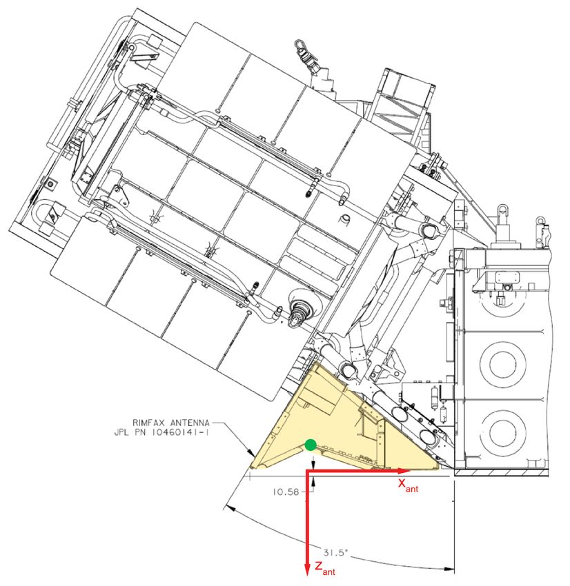
M2020 RIMFAX Calibrated Data Record SIS July 22, 2021

coordinate frames (e.g., RNAV, RAF) until a new one is defined. This method reduces
accumulating error in offset as the rover and mission progress. The specific Site frame (and
corresponding longitude, latitude, and elevation of the Mars surface) pertinent to any RIMFAX
measurement and RAF offset is referenced and accessed by means of the Rover Motion Counter
(RMC) index “system_rmc_site”, which is included in EDM/EHK metadata and in the
measurement’s CDR data record (along with several other RMCs).
The RIMFAX Antenna Coordinate Frame
It is the position of RIMFAX’s antenna, rather than the rover, that is most relevant to RIMFAX
measurements and their location with respect to contextual features on or below the surface of
Mars. Specifically, the physical location on the antenna from which the radar signal emanates is
conceptualized by a point referred to as the antenna feed point (AFP). The RIMFAX AFP is
located on the underside of the antenna near the apex of the antenna peak, laterally centered. It is
this physical point that is attributed a two-way travel time delay value of 0 ns in the “time zero”
correction step of RIMFAX CDR processing (Section 3.2.2). The origin of RAF (introduced
above) is defined by the downwards projection of the AFP (perpendicularly) onto the horizontal
basal plane of the antenna, which represents the RAF X-Y plane (Figure 5).
The RIMFAX antenna is rigidly affixed to the rover, can not move independently, and has no
moving parts or mechanisms. It is precisely aligned to point nadir, is centered on the rover’s
longitudinal axis, and all 3 dimensions/axes of the RAF are parallel with their respective rover
(RMECH and RNAV) counterparts: the RAF +X axis points to the front of the rover, +Y points
to the right side of the antenna, and +Z points down (perpendicular to the chassis deck, which is
perpendicular to the Mars surface below if the antenna and rover are on a flat, horizontal
surface). The RAF is defined with respect to RMECH, which in turn is defined in terms of
RNAV. These defining, constant offsets (individual and net) are clearly all translational, with no
rotational components (Table 7). Thus, determination of the rover’s position and orientation
effectively prescribes those of the RIMFAX antenna.
It is important to note that the AFP, equivalent to “time-zero” in radar soundings, is above (-Z
direction) the RAF origin on the antenna basal (X-Y) plane by ~5.8 cm. Thus, the AFP-RNAV
net vertical distance is ~74.4 cm. This quantity is significant as the nominal AFP-Mars surface
distance (on flat, horizontal ground), and is useful for constraining the location of the surface
reflection return in radar sounding data by the return’s time delay.
Table 7: Translational offsets defining the RIMFAX Antenna Frame (RAF) with respect to the
Rover Mechanical frame (RMECH) and the Rover Navigational frame (RNAV). Individual
frame-to-frame as well as net RAF-RNAV offsets are given. There are no rotational offsets among
these coordinate frames. * Antenna feed point (AFP) - RNAV offset is ~744 mm.
 Reference Translational Offset (mm)
 Frame
 Frame X Y Z
 RAF RMECH -1104.8 0 +447.6
 RMECH RNAV +90.02 0 -1133.38
 RAF RNAV -1014.8 0 -685.8*

 20
M2020 RIMFAX Calibrated Data Record SIS July 22, 2021

Figure 5: The RIMFAX antenna, highlighted yellow, is mounted to the aft of the rover, beneath
the MMRTG (large, tilted, square object). The RIMFAX Antenna coordinate Frame (RAF) is
identified here by its X and Z axes (red, Y pointing out of page); its origin is on the antenna basal
(X-Y) plane, directly beneath the antenna feed point (AFP, green dot).

3.3.3 Data Storage Conventions
RIMFAX Calibrated data products are stored as ASCII text Comma Separated Value (CSV)
tables. Each CSV table has a detached PDS4 label in XML format.

 21
M2020 RIMFAX Calibrated Data Record SIS July 22, 2021

3.4 Applicable Software
None.

3.5 Backups and Duplicates
The Geosciences Node keeps two copies of each archive product. One copy is the primary online
archive copy, another is a backup copy. Once the archive products are fully validated and
approved for inclusion in the archive, a third copy of the archive is sent to the National Space
Science Data Coordinated Archive (NSSDCA) for long-term preservation in a NASA-approved
deep-storage facility. The Geosciences Node may maintain additional copies of the archive
products, either on or off-site as deemed necessary.

4 RIMFAX Archive Organization, Identifiers and Naming Conventions
This section describes the basic organization of the RIMFAX archive under the PDS4
Information Model [1, 3], including the naming conventions used for the bundle, collections,
data product unique identifiers, and data product files.

4.1 Archive Structure
The highest level of organization for a PDS archive is the bundle. A bundle is a set of one or
more related collections that may be of different collection types. A collection is a set of one or
more related basic products that are typically all of the same product type. Bundles and
collections are logical structures, not necessarily tied to any physical directory structure or
organization. A product consists of a file containing one or more digital objects (e.g., a table of
data, an image, or a document) and described by an accompanying label file.

4.2 Logical Identifiers
Every product in PDS is assigned a Logical Identifier (LID)that allows it to be uniquely
identified across the system. Each product also has a Version Identifier (VID) that allows
different versions of a specific product to be referenced uniquely. A product’s LID and VID are
defined as separate attributes in the product label. For convenience they may be combined in a
single string called a LIDVID, with two colons between the LID and the VID. LIDs and VIDs
are assigned by PDS and are formed according to the conventions described in Sections 4.1.1
and 4.1.2 below. The uniqueness of a product’s LID and VID may be verified using the PDS
Registry and Harvest tools.

4.2.1 LID Formation
LIDs take the form of a Uniform Resource Name (URN). LIDs are restricted to ASCII lower
case letters, digits, dash, underscore, and period. Colons are also used, but only to separate
prescribed components of the LID. Within one of these prescribed components dash, underscore,
or period are used as separators. LIDs are limited in length to 255 characters.
M2020 RIMFAX LIDs are formed according to the following conventions:
 ● Bundle LIDs are formed by appending a bundle-specific ID to the base ID:

 22
M2020 RIMFAX Calibrated Data Record SIS July 22, 2021

 urn:nasa:pds:
 Example: urn:nasa:pds:mars2020_rimfax
 The bundle ID must be unique across all products archived with the PDS.
 ● Collection LIDs are formed by appending a collection-specific ID to the collection’s
 parent bundle LID:
 urn:nasa:pds: :
 Example: urn:nasa:pds:mars2020_rimfax:data_calibrated
 Since the collection LID is based on the bundle LID, which is unique across PDS, the
 only additional condition is that the collection ID must be unique across the bundle.
 Collection IDs correspond to the collection type (e.g. “browse”, “data”, “document”,
 etc.). Additional descriptive information may be appended to the collection type (e.g.
 “data_raw”, “data_calibrated”, etc.) to ensure that multiple collections of the same type
 within a single bundle have unique LIDs.
 ● Product LIDs are formed by appending a product specific ID to the product’s parent
 collection LID:
 urn:nasa:pds: ::
 Example:
 urn:nasa:pds:mars2020_rimfax:data_calibrated:rimfax_calibrated_0001
 Since the product LID is based on the collection LID, which is unique across PDS, the
 only additional condition is that the product ID must be unique across the collection.
 Often the product LID is set to be the same as the data file name without the extension.
 See section 4.5 below for examples of RIMFAX data product LIDs.

4.2.2 VID Formation
Product VIDs consist of major and minor components separated by a “.” (M.n). Both
components of the VID are integer values. The major component is initialized to a value of “1”,
and the minor component is initialized to a value of “0”. The minor component resets to “0”
when the major component is incremented. The PDS Standards Reference [1] specifies rules for
incrementing major and minor components.

4.3 RIMFAX Bundle
The complete M2020 RIMFAX archive is organized into a single bundle as described in Table 8
[9].
Table 8: The RIMFAX Bundle.
 Bundle Logical Identifier Description
 urn:nasa:pds:mars2020_rimfax The RIMFAX Bundle.

 23
M2020 RIMFAX Calibrated Data Record SIS July 22, 2021

4.4 RIMFAX Collections
The RIMFAX Bundle contains the three collections listed in Table 9 [9].
Table 9: Collections in the RIMFAX Bundle.
 Collection
 Collection Logical Identifier Content Description
 Type
urn:nasa:pds:mars2020_rimfax:data_raw Data Contains RIMFAX raw data
 products, in varied formats.
urn:nasa:pds:mars2020_rimfax:data_hk Data Contains RIMFAX housekeeping
 data products, in varied formats.
urn:nasa:pds:mars2020_rimfax:data_calibrated Data Contains RIMFAX calibrated data
 products, in CSV format.
urn:nasa:pds:mars2020_rimfax:browse_radargram Browse Contains browse radargram products
 compiled from traverse sounding
 data for select calibrated data
 products, in PNG format.
urn:nasa:pds:mars2020_rimfax:document Document Contains documentation, including
 this Calibrated Data SIS, the Raw
 Data SIS, the Archive Bundle SIS,
 and the RIMFAX Calibrated Catalog.

4.5 RIMFAX Calibrated Data Products
Each Calibrated data product (or Calibrated Data Record, CDR) within the RIMFAX data
collection contains a text file (CSV format), along with its respective label file. An example of
such a data product and corresponding LID is given in Table 10. These CDR file pairs are
organized into subdirectories by Earth year, named, e.g., 2021, 2022, etc.
Table 10: Example of data product LID in the RIMFAX calibrated data collection.
 Example Calibrated Data Product LID Description
urn:nasa:pds:mars2020_rimfax:data_calibrated:rimfax_calibrated Contains a CSV-format text file,
_0001 composed of a single data table.

4.6 RIMFAX Calibrated Data Product File Naming Conventions
RIMFAX Calibrated data product files (CSV format) contain one Sol’s worth of data and are
named according to the format:
 rimfax_calibrated_.
For example:
 rimfax_calibrated_0001.csv
 rimfax_calibrated_0001.xml

 24
M2020 RIMFAX Calibrated Data Record SIS July 22, 2021

5 RIMFAX Product Formats
Data that comprise the RIMFAX data archive are formatted in accordance with PDS
specifications [1 - 6]. This section provides details on the formats used in the types of products in
the RIMFAX archive.

5.1 Data Product Formats
This section describes the format and data-table record structure of the CSV-format text file
within the Calibrated data product.

5.1.1 Raw Data File Structure
RIMFAX Raw data products are not described in this SIS, but are described in [8].

5.1.2 Calibrated Data File Structure
The CDR data product is a CSV-format text file composed of a data table of ASCII text fields.
This data table includes all processed radar measurements, housekeeping data, calibration arrays,
and associated parameters.
The first record (row) of the table contains column headings. The next several records (minimum
of 3 in all Sols with radar measurements) contain one of the three types of calibration arrays
discussed in Section 3.2.2. Each subsequent record contains data from a single measurement,
either radar data or housekeeping data, in chronological order down the table (Figure 6).
The first column of each record contains the parameter record_type, which indicates which type
of information the record contains, according to Table 11.
Table 11: Fundamentally different types of records in the RIMFAX CDR data product data table,
as identified by the data-table parameter “record_type” (in the first column of each data-table
record).
 Value of record_type
 Record Type Data-Sample Columns Content
 Parameter
record_type = 0 Active sounding data time-domain data samples
record_type = 1 Passive radiometry data frequency-domain data samples
record_type = 5 Housekeeping data empty
record_type = 8 Calibration array time-domain or frequency-domain elements

The next dozens of columns (N=85) of each record contain fields of parameters associated with
that record’s data (listed and described in Appendix A). Depending on which type of record it is
(according to Table 11), some or many of these fields may be empty (in the CSV data format, an
empty field would have no ASCII character between the two commas bounding the field).
The latter range of columns (typically N=100s - 1000s) contain radar-data samples (either active
sounding data in the time domain or passive radiometry data in the frequency domain) or

 25
You can also read