RDS RAILWAY DEFORMATION SYSTEM - Sisgeo
←
→
Page content transcription
If your browser does not render page correctly, please read the page content below

RDS RAILWAY DEFORMATION SYSTEM
RDS
RDS
RAILWAY DEFORMATION SYSTEM
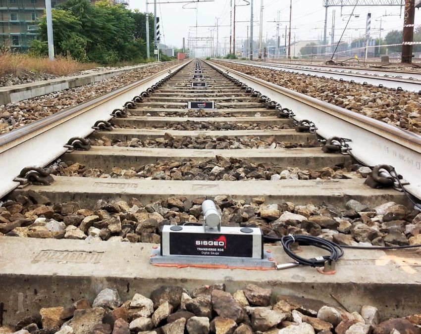
The RDS (Railway Deformation System) is a system designed
and developed for the automatic monitoring of railways.
RDS consists of a digital MEMS tiltmeter mounted parallel or
transverse to the track. Micro-prisms can be installed on RDS-T gauges
to integrate the system with optical monitoring.
RDS components are used to monitor settlement, heave, and twist
(cant) of the track. The system is designed to be used on active tracks
to ensure railway safety.
FEATURES
• Provides high accuracy with digital MEMS sensors
• Accommodates thermal expansion by telescopic joint
• Tolerates shock up to 20000 g
• Removes easily when reballasting is required
APPLICATIONS
• Monitors for possible deformations caused
by nearby excavations
• Monitors for stability of temporary supports
for railway tracks
• Monitors for safe operation in areas of possible
settlement or heave
MEMS TECHNOLOGY
Meets the essential requirements of the EMC Directive 2014/30/UE
WWW.SISRAIL.COM RDS_EN_04_07/2021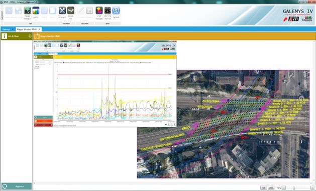
RDS
TECHNICAL SPECIFICATIONS
PRODUCT CODE                                                          RRDSHDT0200                                                           RRDSHDL1000
                                                                                                                                            RRDSHDL2000
                                                                                                                                            RRDSHDL3000

Model
                                                           RDS-T: Transverse RDS gauge                                          RDS-L: Longitudinal RDS gauge
                                                The RDS -T consists of an aluminum sensor body                       The RDS-L consists of a MEMS tilt sensor mounted
                                                  with a steel anchor plate. It can be installed on                        inside square-section aluminum tubing.
                                                concrete or wooden ties (sleepers). It is supplied                      The bar includes telescoping joint at one end,
                                                 with two 2 meter cables and waterproof connec                        an optical target, and an anchor plate. The anchor
                                               tors. The RDS-T is suitable for monitoring of railway                     plate is suitable for concrete ties (sleepers),
                                               tracks with temporary support (i.e. Essen method).                           and has extra mounting holes to allow
                                                                                                                         for up to 150 mm variations in the distance
                                                                                                                                         between ties.

Measurement principle                                     uniaxial MEMS digital inclinometer                                    uniaxial MEMS digital inclinometer

Measuring range                                                   ±10° (±5° on request)                                                 ±10° (±5° on request)

Sensor repeatability                                                       0.0013°                                                               0.0013°

Sensor resolution                                                         0.00056°                                                              0.00056°

Sensor mechanical bandwidth                                                 18 Hz                                                                  18 Hz

Sensor stability @ 30 days (1)
RDS
RDS-T PHYSICAL FEATURES
                                                                                                                       245 mm
PRODUCT CODE                                              RRDSHDT0200
                                                                                                anchor plate

                                                                                                                                            77 mm
Sensor body length                                        245 mm (9.6")

Total height                                               76.6 mm (3")

Installation plate                                295 x 64 mm (11.6" x 2.5")

Materials                                      Aluminum body and steel plate

                                                                                                                                            64 mm
RDS-L PHYSICAL FEATURES                                                                        2 m (6.5 ft)
                                                                                              sensor cable             295 mm
PRODUCT CODE                                              RRDSHDL0000

Length (L)                            1000, 2000 or 3000 mm (L) (3.25 ft, 6.5 ft, 9.8 ft )

Total height                                               86 mm (3.4")

Anchor plate                                           200 x 200 mm (8 x 8")

Materials                                       alluminum bar and steel plate

                                                                   L

                                                                                                                                           86 mm
                                                                                                          15 mm
                      optical
      male                                                                                                                  200 mm
                      target
  connector                                                                                          female
                                                                                                  connector
                                sensor
                                cable

                                                                                                                                           200 mm
                                                                                                      anchor
                                                            40 mm (1.6")                                plate

                                                                                                                          150 mm (6")
                                                                                                                        adjustable range

TELESCOPIC JOINT                                                                             allowed linear
                                                                                             expansion range
Sisgeo developed a special telescoping joint for the
                                                                                             (about 30 mm)
RDS-L tubing. It accommodates thermal expansion
of the aluminum bar to eliminate possible bending
that would affect the sensor readings.

                                                                       anchor
                                                                         plate
                                                                                                                      optical
                                                                                                                      target

                                                   WWW.SISRAIL.COM                                              RDS_EN_04_07/2021
RDS
RDS-L: LONGITUDINAL   The RDS -L gauges are installed in continuous chain to monitor the longitudinal level
                      of the tracks. The gauge mounting plates are anchored to the ties with screws
DEFORMATIONS          or with special resin.

             RDS-L                                                                            rail

                         tie
                                                                                         longitudinal
                                                                                         level

                                                                             tunnel in
                                                                             construction

       EXCAVATION ZONE OF INFLUENCE

                      The RDS-T are installed to monitor the inclination of the ties and consequentely
RDS-T: TRANSVERSE     the cant (or “skew”) of the railway. The twisting is usually expressed in ‰ as the
                      relative inclination of one rail Vs the other.
DEFORMATION

                                                                                                        tie
                                                                    rail         RDS-T

           UNDERPASS IN CONSTRUCTION WITH

          PUSHED MONOLITHIC CONCRETE BOX

                                 WWW.SISRAIL.COM                               RDS_EN_04_07/2021
RDS
OPTICAL-RDS INTEGRATED SYSTEM
The OPTICAL - RDS integrated system consists of a number of RDS-T gauges, each with a micro prism for optical
monitoring. The RDS-T gauges are usually installed on the sleepers at 1 m, 3 m or 9 m intervals. Longitudinal
deformations are measured with an high-accuracy (0.5”) robotic total station, able to detect the vertical position
of the micro prism and, with processing, the settlement or heave of the tracks. Transverse deformations are
monitored with the RDS-T gauges, all connected to an RS-485 bus by waterproof 5-pin connectors, and then to the
OMNIAlog through a junction box and digital cable. Both the robotic total station and the OMNIAlog data logger
collect and send data to an SQL database through GSM/GPRS modem, 3G/VPN router, fiber optic cable, radio or
satellite interface. The web platform WMS (Web Monitoring System) validates, processes, converts, manages and
publishes data on dedicated web pages, as requested by the customer. RDS-T gauges are developed for easily
removal when reballasting is required or when the system must be moved to a different location. The OPTICAL -
RDS integrated system is recommended when the monitored area is too long for RDS-L gauges. Optical systems
are not recommended where there is heavy fog or rain. Also, it should be noted that microprisms must be cleaned
monthly to remove dust created by train braking systems

                                                    SQL
                                                  database

                                                                                RDS-T gauge
                                                                             with micro-prism

            robotic
      total station

                                        WWW.SISRAIL.COM                             RDS_EN_04_07/2021
RDS
                      The RDS system consists of a number of RDS-L and RDS-T gauges spanning the entire area
RDS SYSTEM            where track deformation may occurs. RDS-L are installed in continuous chain, and RDS-T
                      are installed at preset intervals (usually 1 m, 3 m or 9 m). All the gauges connected to an
                      RS-485 bus by waterproof 5-pin connectors. The RS-485 bus cable is terminated in the junction
                      box included with the RDS terminal kit (RRDSTER5M00). A digital cable 0WE606IPDZH
                      carries the data from the junction box to an OMNIAlog datalogger. The OMNIAlog datalogger
                      collects and sends RDS system data to an SQL database through GSM/GPRS modem, 3G/VPN
                      router, fiber optic cable, radio or satellite interface. The web platform WMS (Web Monitoring
                      System) validate, processes, converts, manages and publishes data on dedicated web pages,
                      as requested by the user. RDS gauges are developed for easily removal when reballasting
                      is required or when the system must be moved to a different location. The rugged RDS
                      system tolerates hard weather and wide temperature ranges. All the components have IP67
                      protection minimum and a working temperature range of -30°C to +70°C .
                      If the railway section to be monitored is very long, small errors may accumulate.
                      In that case, the OPTICAL - RDS integrated system is recommended.

                                                                SQL
                                                              database
         OMNIAlog
         datalogger

                                        signal cable                                         junction box
                                        0WE606IPDZH                                          (included in the
                                                                                             RDS terminal kit
                                                                                             RRDSTER5M00)

                                                                                             RDS-L gauge
                                                                                             (product code
                                                                                             RRDSHDL0000)

                                                                                             telescopic
                                                                                             joint

                                                                                             RDS -T gauge
                                                                                             (product code
                                                                                             RRDSHDT0200)

                                  WWW.SISRAIL.COM                                RDS_EN_04_07/2021
RDS
accessories and spare parts
RRDS00LE000 RDS-L TERMINAL ANCHOR PLATE, anchor plate used to terminate the RDS-L chain.
It accommodates 150 mm of length adjustment, just as other anchor plates.
RRDS00LSP00 RDS-L SPARE ANCHOR PLATE, used when an RDS-L must be moved to a new location, and its anchor
plate cannot be moved with it.
rRDS00LWP00 PLATE FOR WOODEN Ties, steel anchor plate for mounting RDS-L
0WE606IPD2H DIGITAL SIGNAL CABLE, Used to connect the junction box of the RDS terminal kit to the datalogger.
Cable has three twisted pairs (4x0.22 mm2, 2x2.0 mm2).
0ETERMRESI0 RESISTANCE ENDING DEVICE, termination resistance with connector, needed to close every digital RDS chain.
The value of resistor depends on the layout of each system. For more detail see the FAQ#076.
RRDSTER5M00 RDS TERMINAL KIT, Includes 5 m digital cable with waterproof connector to connect the closest RDS
gauge and junction box.
rRDS00TSP00 RDS-T SPARE ANCHOR PLATE,used when an RDS-T must be moved to a new location, and its anchor plate
cannot be moved with it.
RDS-L SPARE ANCHOR PLATE PLATE FOR WOODEN Ties RDS-T SPARE ANCHOR PLATE
READABLE BY
Refer to separate datasheets for further
information.
NEW LEO OMNIALOG
WWW.SISRAIL.COM RDS_EN_04_07/2021RDS
WMS the ADVANCED DATA management platform
FIELD S.r.l., part of Sisgeo Group, has developed a dedicated service
for data/measurement management from automatic and manual
monitoring systems called WMS (Web Monitoring System).
The measurements provided by each gauge, are requested and stored
in OMNIAlog, miniOMNIAlog or other DAS, sent to a Server and
imported to a dedicated Database, where they are divided by project,
instruments and measurements. Data are later validated, processed
and represented in graphic and table format.
The WMS platform allows quick visualization in real-time of the charts,
showing both the measurements of the maximum drawdown at each
recorded event and the detected inclinations and temperature.
For further information, visit the dedicated web page on the Field Srl
web site: https://www.fieldsrl.it/en/services/data-management/
READINGS
(.xlsx, .csv, .xml, etc...)
SERVER
INSTRUMENTS WMS.FIELDSRL.IT
This WMS screenshot
shows the position
of the RDS gauges on
job site with nine tracks
where an underpass
is being constructed.
The plot represents the
railway twisting. Alert
and alarm thresholds are
represented by straight
yellow and red lines.
AFTER SALES SUPPORT
a sisgeo brand
SISGEO offers customers e-mail and phone assistance to ensure proper use
Via F. Serpero 4/F1
of instruments and readout and to maximize performance of the system.
20060 Masate (MI) Italy
For more information, email us: assistance@sisgeo.com
Phone +39 02 95764130
Fax +39 02 95762011
All the information in this document is the property of Sisgeo S.r.l. and should not be used without permission from
info@sisgeo.com
Sisgeo S.r.l. We reserve the right to change our products without prior notice. The datasheet is issued in English and other
languages. In order to avoid discrepancies and disagreement on the interpretation of the meanings, Sisgeo Srl declares that
WWW.SISRAIL.COM English Language prevails.
WWW.SISRAIL.COM RDS_EN_04_07/2021You can also read