Modifying a Nikon D80 for IR photography
←
→
Page content transcription
If your browser does not render page correctly, please read the page content below
Modifying a Nikon D80 for IR photography
Dan Desjardins – Former Camera Repair Tech
Note: Before beginning remove the battery and put a body cap on the camera! Also – read
these entire instructions through – from beginning to end before starting your conversion.
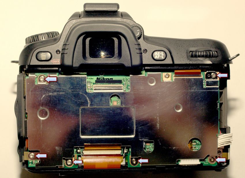
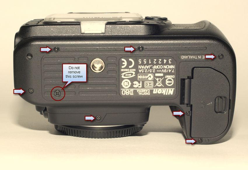
Step 1 – Remove the bottom plate
The blue arrows indicate which screws need to be removed.
Note: These screws all vary in length. I arrange the screws on a piece of paper in a pattern that
represent the location of each screw as I remove them.
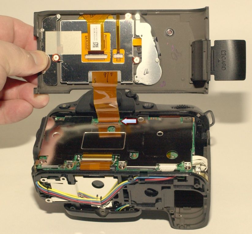
View with the bottom removed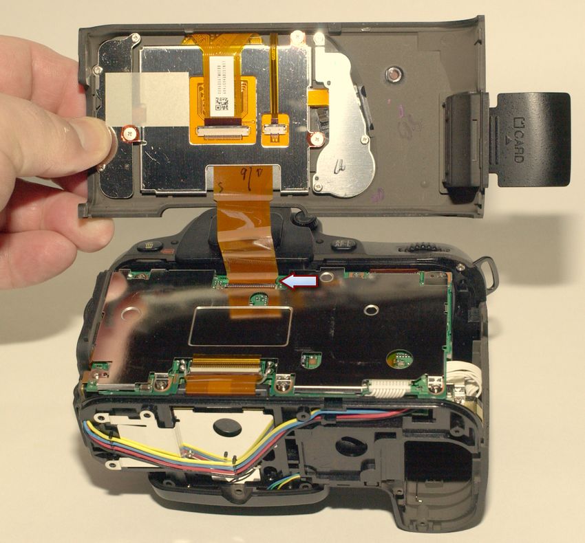
Step 2 – Remove 4 screws from each side to remove the back

With these four screws removed you can carefully slide the back off the camera. There is a
single ribbon‐cable that will still be attached so do not pull hard or you will damage the cable
and/or the connector.
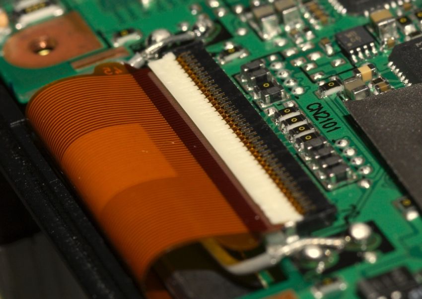
A Quick Discussion on the Ribbon Cables

All ribbon cables are connected via a tricky connector. Here is an explanation of how to
remove and reinsert these cables.

All ribbon cables use a flat connector with a flip‐up lock. Do not try to remove the cable
without flipping up the lock.

You can use a small flat‐head screwdriver to flip the lock up. Carefully run the screwdriver
underneath the lock while gently forcing up upwards. It will “snap” up.
Once the lock is flipped up you can easily and safely slide the ribbon cable out.

                                 Æ

                  Side view of ribbon connecter and lock

Again – all of the ribbon cables are locked into their connectors like this. It is very easy to
remove the cable once you flip up the lock. To reinsert the ribbon cable you must make sure
the lock is UP – and have patience as reinserting the ribbon cables is tricky.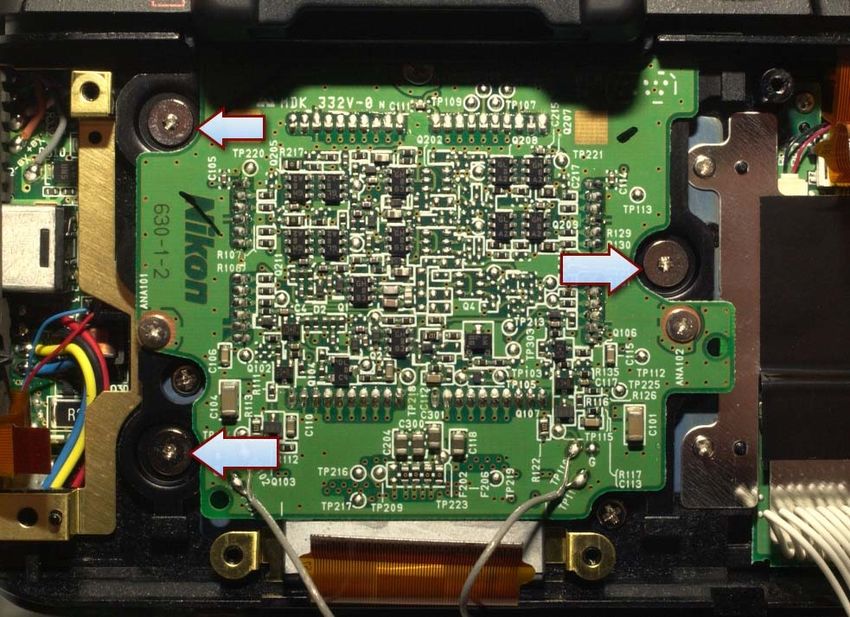
Step 3 – Remove the Ribbon Cable Connecting the Camera Back

As per the discussion on the ribbon cable connectors above – unlock the ribbon cable that
connects the back of the camera to the main circuit board and set the back aside.
Step 4 – Remove the RF Shield

Remove the screws (There are 6, see the blue arrows in the image above) and remove the RF
Shield. All of these screws are the same. It is a good idea not to get fingerprints on this shiny
metal shield – that is a telltale sign of an amateur job.
Step 5 – Remove Two Ribbon Cables (one on the left and one near the bottom)

There are 4 ribbon cables to remove in all. You have already removed one (from the camera
back). These two need to be liberated before you can remove the circuit board. One ribbon
cable will be easier to remove once you have loosened the circuit board (next step).

Both of these ribbon cables use the locking mechanism discussed earlier in this document.
Step 6 – Remove the Circuit Board
There is only one screw now holding the circuit board in place (See the blue arrow), Remove it
and gently lift the circuit board away from the camera. The left side of the board hosts several
A/V connectors that are fitted into several holes on the left. It will be a little tricky to pull this
away as those connectors make it impossible to lift the board straight up. You will have to
finesse the board a little to the right as you gently lift it from the camera.

Once you have liberated the circuit board the remaining cables will be easier to remove.
Step 7 ‐ Disconnect the rest of the cables
There are three cables left to remove. One is a
ribbon cable (upper right side) and two are wired
connector with header pins.
With the circuit board lifted away from the camera
you can easily remove the last ribbon cable as well
as the two header‐pin connectors. The header‐pin
connectors simply pull out. Notice that one of the
header‐pin connectors is underneath and on the
bottom of the circuit board.
Note: Do not pull the header‐pin connectors out by pulling on the wires. Though the connectors
are not locked in place – you should use a small screwdriver to gently coax the connectors
from their receptacles. Also – keep the wires combed neatly to keep the work looking
professional.
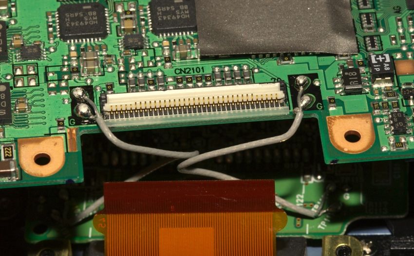
With all of the cables removed you can now pull the circuit board away from the camera – but
you will notice that there are two soldered wires that prevent you from setting the board aside.
There is no need to desolder these wires – in fact it is absolutely best not to. These are two‐
conductor shielded wires and unless you have a great deal of experience soldering wires like
this you will do more damage than good. Even if you have experience – there really is no need
to remove these wires. Nikon left plenty of service‐length to allow you to do this project safely
without soldering anything.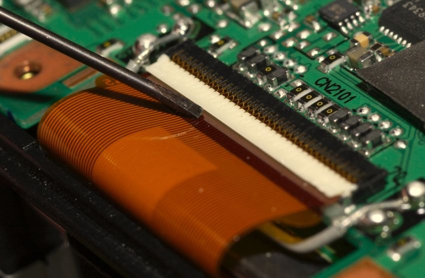
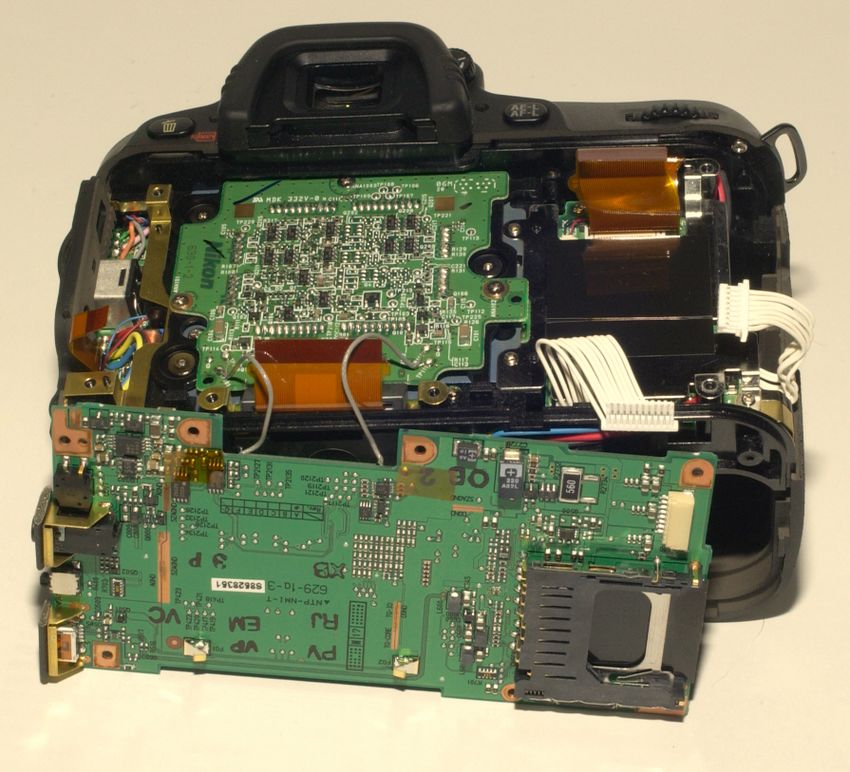
Carefully flip the circuit board over and set it down as per the image below
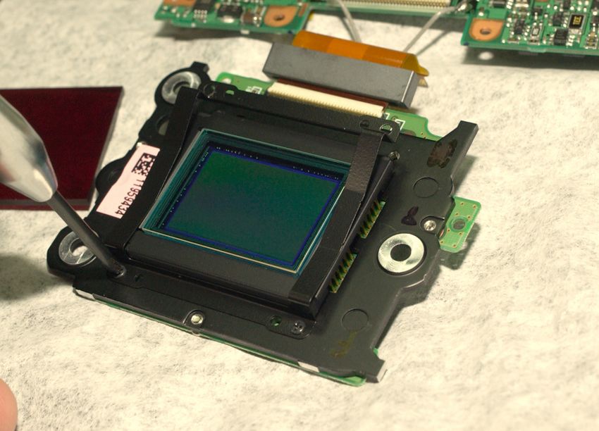
Step 8 – Remove the sensor board
It is now time to remove the circuit board on which the image sensor is mounted. This is done
by removing only three large‐headed screws. These are very unusual screws as they have a
very large head but they require a #0 Phillips head screwdriver.

These are very tight and you will need a lot of downward pressure on the screwdriver to
accomplish removal.

Note: Make sure you are using a very high‐quality #0 Phillips screwdriver. Use of a cheap and
      improperly sized screwdriver will round the heads of these screws and make removal
      nearly impossible.

                                               Once you have liberated the sensor board you
                                               can set the camera body aside and work on
                                               replacing the filter.
Step 9 – Replacing the Filter
Clean your new IR filter before proceeding. Make sure it is completely dust free. See the
section on dust control later in this document and follow it carefully.
The filter is mounted to the front of the sensor by a spring‐clip held in place by four screws.
Remove the four screws and the thin metal housing surrounding the current filter (it just lifts
off – but fits on the filter snugly). The filter feels as though it is glued to the front – but it is
not. It has just been compressed against a rubber gasket for a long time – and therefore is
essentially suctioned to the sensor. Finesse the old filter off, do one final ZeroStat and Blow‐
Off (see dust control later) on the filter and sensor with canned air and place the new IR filter in
its place.
Note: Dust here is a problem. Make sure the new filter is absolutely clean – at least on the
inside. See the appendix on dust control for the home shop. Remove the old filter and
replace it with the IR filter as quickly as possible. Failure to remove all of the dust will
result in permanent spots on your images and you will have to redo this entire process to
clean the inside of the filter. You can always clean the outside of the filter without
disassembling the camera.Step 10 – Reassembly This document does not go into detail on reassembly. If you have made it this far you must have the necessary skills to reverse the process and put everything back. The tricky part is reinserting the ribbon cables – this will take patience and finesse. Make sure you slide them into the connectors with the locks in the UP position – and make sure they slide in all the way. Sliding them in only partially will result in an improper connection and your camera will not function. Once it is in place be sure to push the lock back down. It will snap down. Keep everything neat – do not let anything look sloppy. Sloppy work usually means poor work and almost always results in poor performance. When placing the sensor board back on the camera be certain the three screws holding it are very tight – but do not round the Phillips heads or future repairs will be expensive and difficult.
Dust Control
Keeping dust to a minimum is extremely important. Unless you have a laminar‐flow workbench
(they cost thousands) there are some simple steps you can follow to create a good dust‐free
environment without one.
Start by thoroughly cleaning and dusting the entire room where you will be working. Use a new
and clean dusting cloth (A fresh cloth diaper is my favorite). Use some EndustTM. Next, run a
room air cleaner and ultrasonic humidifier filled with distilled water for at least 24 hours in the
shop where you plan to work. Close off the room for the 24 hours.

       Note: Do not use plain water in the humidifier – as it will deposit a fine
             calcium dust on EVERYTHING in the room. If you do not have distilled
             water then do not run the humidifier! It is best if you do though – this
             will control dust and reduce static electricity.

When you work you should wear a simple cotton T‐Shirt and lint‐fee cotton gloves (Ok – the
pictures show I did not wear gloves – I didn’t have any at the time so I was just extra careful).
You can get cotton gloves cheaply on eBay – make sure you order the lint‐free variety! Wash
your hands thoroughly and then use hand cream on your hands AND arms. Wearing a mask is
a good idea, but not entirely necessary. Also put a plastic bag on your head – er just over your
hair!

Some suggested tools

A ZeroStat Gun is a valuable tool               Scotch Tape

              Canned Air                             Coffee Filter(s)
Cleaning the filter
Use lens tissue and 95% isopropyl alcohol (available at Walgreens). Do not scrub. For the final
preparation use good quality Scotch Tape on the surface of the filter. Yes – that sounds odd,
but you can use Scotch Tape to remove all remaining dust from the filter. Simply put the tape
directly on the filter and peel it off. You can do this multiple times. If it is good quality tape,
and fresh it will not leave any residue on the filter. I actually learned this trick from a Nikon
Rep about 27 years ago for cleaning lens elements.
There is a tiny concern that doing this will put a static charge on the filter. I use my static‐
master to neutralize that quickly – but honestly if you pull it off slowly there will not be a
problem. This is more of a concern with a plastic filer (e.g. the Edmund Optics filter) then with
the glass filter from LifePixel – but in my opinion it’s not really a concern with either.
Cleaning a filter with Scotch Tape
If you have a ZeroStat (I have one I purchased in 1982 that still works a treat) use it. Finally
use canned air to blow away any remaining dust.
Note: Do not over‐blow using canned air. Blowing creates a vacuum behind the stream –
which often pulls dusty air with it.
Once the filter is clear place it on a coffee filter. Coffee filters are very clean and dust free.
This is a good place to put a clean IR filter just before you deploy it.
Note: When using canned air always hold the bottle straight up – NEVER tilt it. If tilted, the
canned air will release some of propellant – which will force you to clean the filter all over
again.You can also read