SEALED ENCLOSURE COOLING - INSTALLATION GUIDE - ABOVE AMBIENT COOLING - ACT-TEC-90 THERMOELECTRIC COOLER
←
→
Page content transcription
If your browser does not render page correctly, please read the page content below
ADVANCED COOLING TECHNOLOGIES
             The Thermal Management Experts | www.1-ACT.com

SEALED ENCLOSURE COOLING

    ABOVE AMBIENT COOLING

                                                  DFX AND STEP
            ACT-TEC-90                           FILES AVAILABLE

ACT-TEC-90 THERMOELECTRIC COOLER

     INSTALLATION GUIDE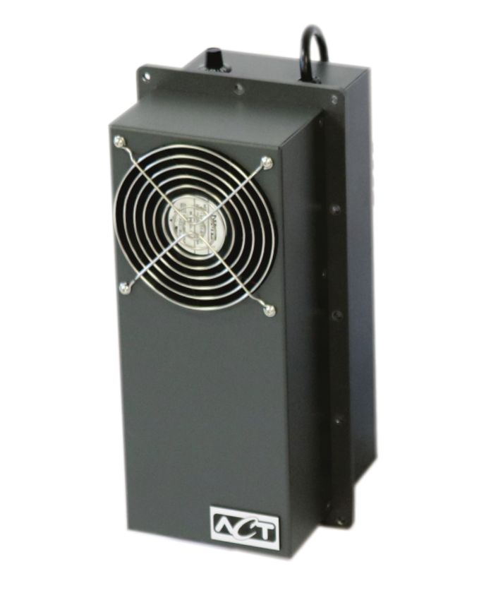
OPERATION

                                                 CAUTION
    BEFORE INSTALLING AND USING THE ACT-TEC PRODUCT, IT IS IMPORTANT THAT THIS MANUAL BE
    READ AND UNDERSTOOD THOROUGHLY.

    The ACT-TEC 90 Thermoelectric Air Conditioners series are
    compact, solid state air conditioners. They cool the internal
    enclosure space with highly reliable Peltier cooling. The Peltier
    cooling cycle involves no moving parts, compressors, CFC
    refrigerants or circulating liquid. They provide reliable cooling
    twenty four hours per day, seven day per week, even in the
    toughest environments.

    ACT-TEC units can be used in wash-down spray-down
    applications or mounted directly to outdoor cabinets to operate
    flawlessly year round. Standard stocked units are available in
    several weeks. Dual mode operation of cooling and heating are
    available.
                                                                                          The ACT-TEC-90 can be
                                                                                          mounted on the control cabinet in
                                                                                          any desired orientation

                                           TOP VIEW TEC-90

                              WARM AIR                          COLD AIR
                                                       WARMER

                                                                           Hot Air From
                                                       COLDER

               Ambient Air
                                                                            Enclosure

                  Rejected Internal Heat
                      Exhausted to                                         Thermoelectric Modules
                       Ambient Air                                Cool the Internal Cabinet via Circulating Fans

                                             Enclosure Wall

    Top View of the ACT-TEC-90 with arrows showing the airflow patterns of the internal and external air streams

2                                                                                                     W W W.1-ACT.COM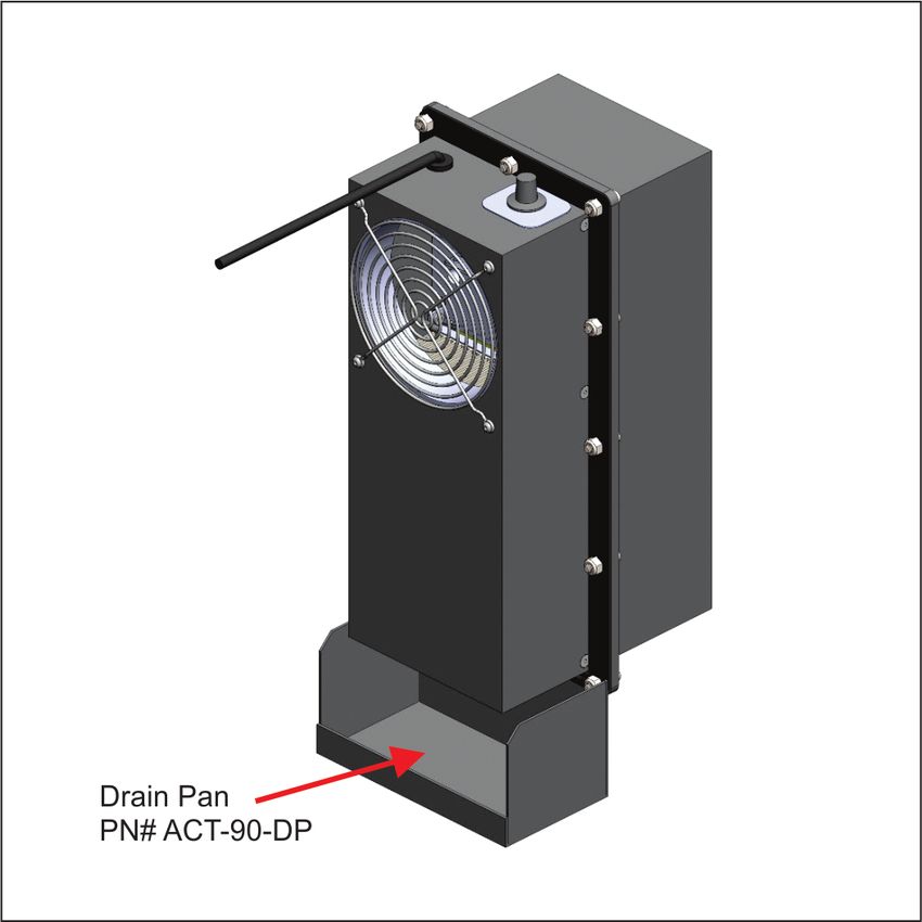
OPERATION

                                                  WARNING
               TO REDUCE THE RISK OF FIRE, ELECTRIC SHOCK OR INJURY, PLEASE OBSERVE THE
              FOLLOWING: nstallation work and electrical wiring must be done by qualified person(s) in
                accordance with all applicable codes and standards, includingfire-rated construction.

    ACT-TEC-90 Temperature Adjustment                                                                       COLDER   WARMER

    The ACT-TEC-90 Thermoelectric Cooler has an
    integrated temperature potentiometer located on the
    inside enclosure side of the unit. It can be found just
    below the power cord lead.

    The potentiometer features a slot to support a blade
    screwdriver. Turning the potentiometer counter
    clockwise increases the cooling capacity.

    The ACT-TEC-90 is also available with an optional
    drip pan Page 8. This is required in certain high
    humidity environments. The drip pan is optional put
    requires a sealed hole be drilled through the cabinet
    to route a small 1/4” drain hose. The hose should
    be sealed around the through hole that was drilled
    with water resistant silicon sealer

                           ACT-TEC PART NUMBER DESCRIPTION

                           ACT - TEC - 90 - 115 - 12

                 Thermoelectric          Thermal Conductance         Voltage Range       NEMARATING
                    Cooler                                                                NEMA - 12
                                              90 Watt
                                           Cooling Capcity             - 115VAC           NEMA 3R
                                                                       - 230VAC           NEMA 4

3                                                                                                       W W W.1-ACT.COM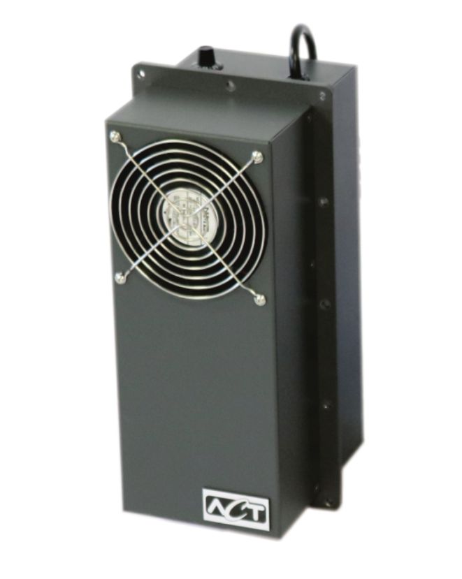
TECHNICAL DATA & DIMENSION
ACT-TEC-90 Thermoelectric Cooler Series Capacities & Dimensions
Cooling Capacity Insertion Mounting
Part Operating NEMA W D
Watts/BTU’s Depth Plate
Number Voltage Ranges Rating (in”) (in”)
at 0°C *Delta T (in”) (in”)
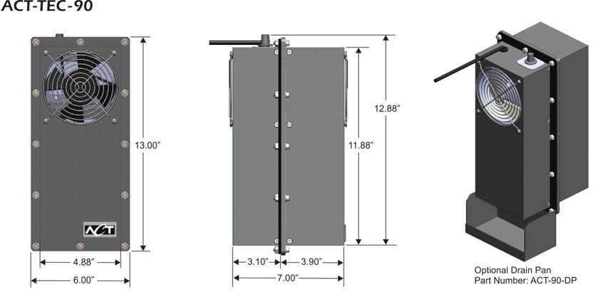
ACT-TEC-90 90/300 115VAC, 12, 3R, 4.88 7.0 3.10 13.0” x 6.0”
230VAC 4
ACT-TEC 90 Performance Chart
140
HEAT DISSIPATED (WATTS)
120
100
80
60
40
20
0
-5 -4 -3 -2 -1 0 +1 +2 +3 +4 +5
DELTA T (°C)
Note: * Delta T is the temperature difference between the inside enclosure temperature to the outside enclosure temperature
ACT-TEC-90 Series Current Draw Chart & Enclosure Cutouts
ACT-TEC-90
Note: All units in inches
ACT-TEC-90-115 ACT-TEC-90-230
115VAC 230VAC
1.8 Amps 0.8 Amps
4 W W W.1-ACT.COM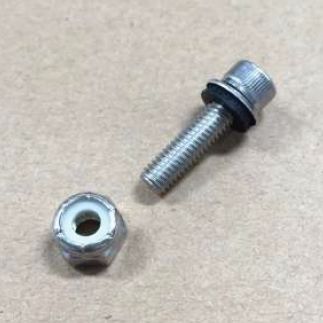
INSTALLATION PROCEDURE
Check for any damage to the box that the unit was shipped in. Remove all shipping foam and inspect the unit for
external damage. Any sign of damage should be documented and reported to the carrier.

Assuming there is no visible damage, stand the unit up vertically so that both air streams are clear and plug the unit
into a power source to verify that the internal and external fan(s) are operational. After successfully completing this
quick test, the ACT- TEC-90 unit is ready for installation.

The following assembly procedure details the installation of a sealed enclosure cooler to the wall of an electronics
enclosure.

Step 1: Determine the location of the cooler on the enclosure. The ACT-TEC-90 can be top or side mounted.
Ensure that you have at least 6” of open space between the fan intake and the next closest enclosure or wall. When
you have decided on a location, use masking tape to outline the square cutout, see figure 2. The cutout dimensions
are shown in the drawings in Appendix A and are available for download in .DXF or SOLIDWORKS® format from the
ACT- Enclosure Cooling Resources area of our website. Start by using a hole saw to establish holes in each corner.
Use a reciprocating saw to make straight cuts between the corner holes, using the masking tape as a reference
edge and to minimize damage to the enclosures surface.

                                                     CAUTION
               The risk of fire, electric shock or injury exists when installing, cleaning or performing
               maintenance on the ACT-TEC unit. ALWAYS DISCONNECT the ACT-TEC from the
               power supply during installation or prior to servicing.

                                                     WARNING
                           TO REDUCE THE RISK OF FIRE, ELECTRIC SHOCK OR INJURY,
                                        PLEASE OBSERVE THE FOLLOWING:
              Installation work and electrical wiring must be done by qualified person(s) in
              accordance with all applicable codes and standards, including fire-rated construction.

5                                                                                                   W W W.1-ACT.COM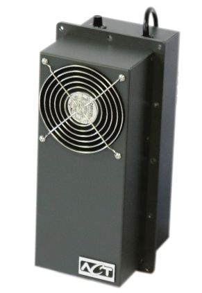
INSTALLATION PROCEDURE

Step 2: Use the edge of the cutout as a reference edge and plot out the perimeter hole locations according to the
drawing shown below in Appendix A. Once the holes have been marked, drill the remaining mounting holes at the
correct location.

Step 3: Deburr the edges of the cutout using a file. Deburr the holes using a countersink bit.

                                                 Risk of injury
                  Carefully deburr all drilled holes and cut-outs to prevent injuries caused by
                  sharp edges.

Step 4: Remove the masking tape and clean any excess cutting oil from the surface/internals of the enclosure.

Step 5: Place the ACT-TEC in position on the wall of the enclosure. The electrical cord should be passed through the
opening in the enclosure prior to inserting the TEC body through the cutout. The ACT-TEC should be oriented so
the gasket contacts the outside surface of the enclosure. Ensure that the gasket surface is free of dust, dirt, and
imperfections and that it makes consistent contact with the external surface of the enclosure.

Step 6: With the ACT-TEC held in place, install the fastening bolts around the perimeter flange of the ACT-TEC.
Make sure the sealing washer is properly located on the bolt as shown in below. The sealing washer is meant to
washer is properly located on the bolt as shown in below. The sealing washer is meant to seat on the external face
of the ACT-TEC (the face opposite the gasket).

6                                                                                                 W W W.1-ACT.COM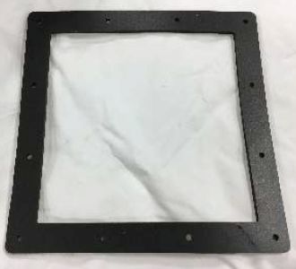
INSTALLATION PROCEDURE

                                                 Caution
                ACT recommends applying an anti-seize lubricant to the threads of the mounting
                                      hardware to prevent galling.

For the ACT-TEC-90 model this step should be completed by two people.
(one person can hold the ACT-TEC in place while the other person installs the hardware.
the HSC in place while the other person installs the hardware).

                                                   Perimeter bolt with sealing washer and locking nut (left)
                                                   perimeter bolts installed on enclosure after being
                                                   torqued down.

                                                    Step 7: Torque the perimeter bolts evenly, alternating
                                                    between bolts in a diagonal pattern so that the sealing
                                                    gasket is compressed in an even fashion. Ensure that
                                                    every bolt is torqued to at least 20 in-lbs.

7                                                                                              W W W.1-ACT.COM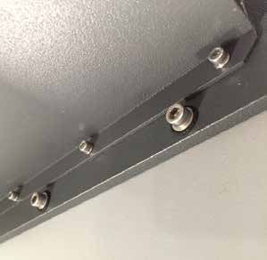
INSTALLATION PROCEDURE
                                      Step 8: Provide electrical power to the ACT-TEC-90 and verify that all fans are
                                      functioning properly. Double check that the fan air intake is clear and that no
                                      enclosure walls or hardware are within 6.0” of the intake or exhaust portion of
                                      the heat exchanger.

                                      Step 9. (Optional): If a rain guard has been selected, it is recommended that the
                                      rain guard be installed prior to mounting the ACT-TEC to the enclosure wall. The
                                      rain guard comes with four (4) self tapping screws. Simply place the rain guard
                                      over the fan opening as shown in below, mark each of the hole locations,
                                      temporarily remove the rain guard and drill a pilot hole (0.136” diameter) at each
                                      mark. Finally, place the rain guard in the original location and fasten it to the
                                      cover using the four self tapping screws.

            ACT-TEC Optional Drain Pan

                     ACT Part Number: ACT-90-DP

                                                              Drain Pan installed
                                                              on the inside of the enclosure
                                                              A small drain house can be added

                                                     CAUTION
    ACT-TEC units are available in a wide range of operating voltages. Make sure the supply voltage matches the
    stated voltage on the ACT factory label. An improper input voltage connection will void the product’s warranty.

    Do not operate the ACT-TEC units without the fan guard properly in place.

    For proper operation make sure that the fan air intake is clear and that no enclosure walls or hardware are
    within 6.0” of the intake or exhaust portion of the ACT-TEC heat exchanger.

8                                                                                                   W W W.1-ACT.COM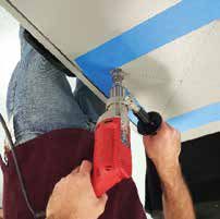
ACT-TEC 90 Dimensions

    www.1-ACT.com/Enclosure-Cooling
    Inquiries: Info@1-ACT.com

    DOC-ACT-TEC-002-G-2020

9                                     W W W.1-ACT.COM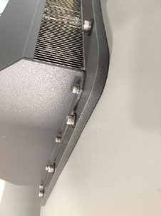
You can also read