Installation Manual: Honda CRV (2017-2018) Power Lift Gate System - Page 1 of 16
←
→
Page content transcription
If your browser does not render page correctly, please read the page content below
Installation Manual:
Honda CRV (2017-2018)
Power Lift Gate System

             Page 1 of 16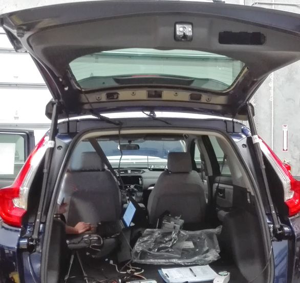
NOTE: Installation Precaution

1. It is recommended to have this product installed by a professional to avoid damage caused by improper
installation.

2. Do not attempt to disassemble or modify any components included within the kit. Unapproved modifications
or evidence of tampering will void any warranty included with the product.

3. Before installation, inspect the vehicle's controls and interior/exterior for any damage or malfunctioning
components. Report any damage or non conformities to the customer prior to installing the product.

4. Inspect the factory lift gate for proper operation and function of lights before installing this product. Improper
opening or closing of the lift gate may interfere with the functionality of the Power Lift Gate System.

5. It is recommended to remove or cover any item of clothing (belt buckles, jeans rivets, buttons, etc) prior to
installation of this accessory to prevent damage incurred to the vehicle during the installation.

6. Interior panels that have been removed should be set aside somewhere safe during the installation process
to avoid damage.

7. When routing and securing wiring harnesses, care should be exercised to avoid any hot, sharp, or moving
objects in the vehicle such as steering column, pedals, dash bracing, HVAC components, etc.

8. Do not deviate from methods of installation in this document. Any damage caused by improper wire routing,
incorrect connections, wiring, etc. is not covered under the warranty.

9. Disconnect the negative (-) battery terminal before proceeding to installation. Wait at least 2 minutes after
disconnecting the negative (-) battery terminal to disable the SRS and other systems in the vehicle. Any dam-
age caused from failure to disconnect the battery is not covered under the warranty.

10. After installation, you must manually close the lift gate to initialize the Power Lift Gate System.

                                                  Page 2 of 16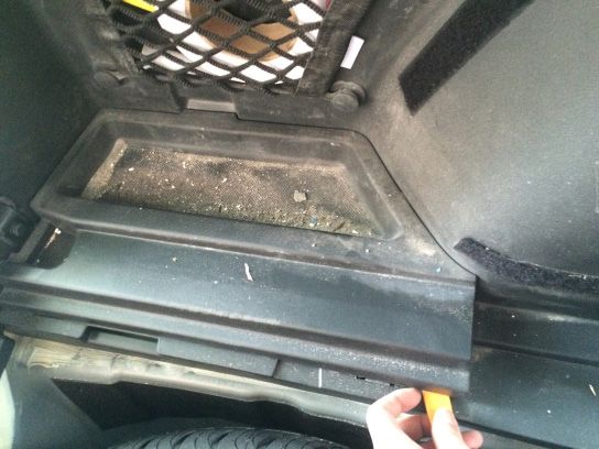
Wiring Details

                 Page 3 of 16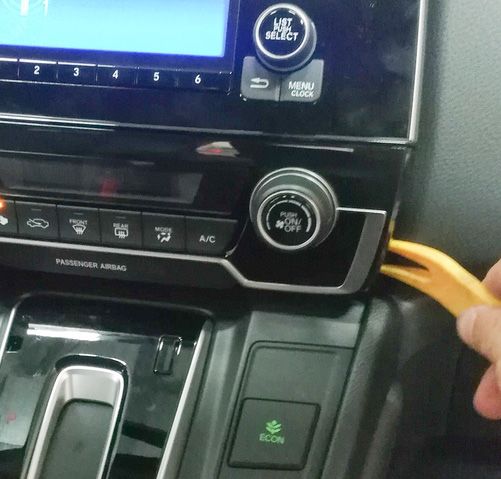
Wiring Details

                 Page 4 of 16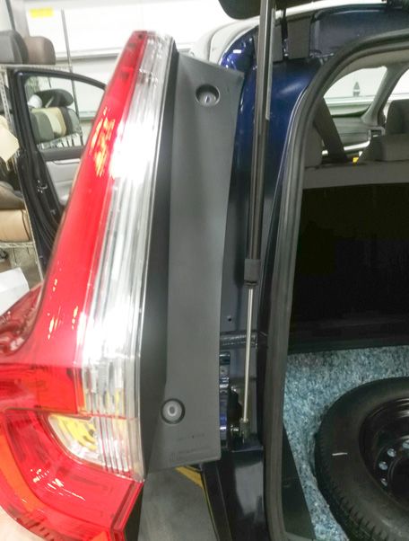
PREPARING FOR INSTALLATION

INSTALLATION PREPARATION

   Before starting installation

1. Familiarize yourself with the installation instructions.

2. Inspect kit components to verify everything is pres-
ent, there is no damage, and to familiarize yourself with
the parts.
                                                                 Negative Battery
 VEHICLE PREPARATION                                             Cable

1. Place protective coverings on vehicle.

2. Apply protective tape to all points before prying.

3. "IMPORTANT........IMPORTANT"
      Disconnect Negative Battery
      Cable

INSTALLATION:

1. Lift and remove the luggage compartment floor
   board.

2. Disengage the clips holding the cloth trim from
   the back of the seats from the floor trim garnish.

                                                  Page 5 of 16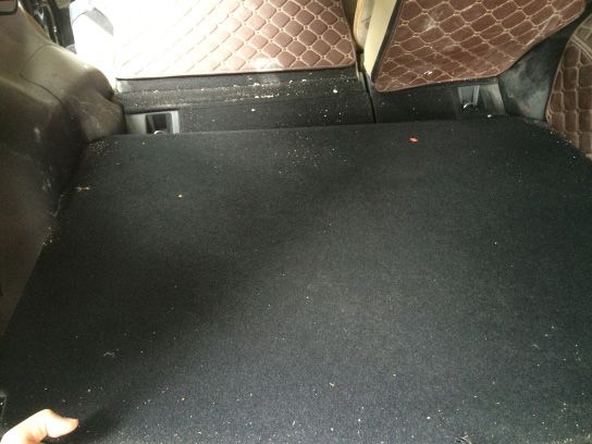
3. Disengage the clips and remove the luggage
   compartment trim garnish from the floor.

4. Use a moulding remover, gently disengage the
   claws and remove the LH side access panel
   behind the LH rear seat.

5. Disengage the claws, and remove the driver's
   side rear door scuff plate.

                                             Page 6 of 16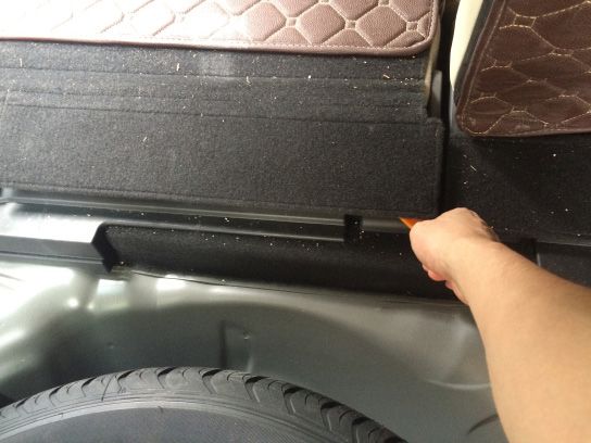
6. Carefully disengage the claws and remove the
   LH rear side trim panel.

7. Remove the hook by depressing the black spot
   in the middle and pulling outward.

8. Remove the cover off of the handle. Then
   remove the (2) screws securing the release
   handle to the wall.

9. Remove the screw to remove the LH tie-down
   cleat. Repeat for the RH side.

                                                Page 7 of 16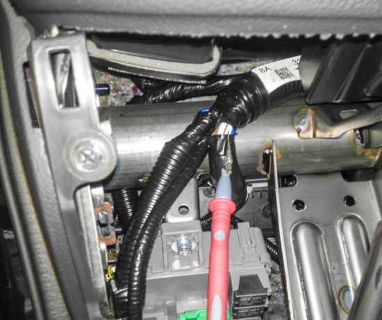
10. Press the center of the clip, and lift up to disen-
  gage the clips from the rear luggage compart-
  ment opening garnish plate.

11. Carefully pry to disengage the clips to remove
   the luggage compartment opening garnish plate.

12. Carefully pry to disengage all of the clips, and
  remove the LH inside quarter panel trim panel.

13. Carefully rest panel in rear of vehicle.

                                                 Page 8 of 16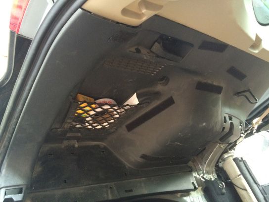
14. Carefully pry to disengage the clips securing
  the upper trim panel to access the connectors
  behind it. It is not necessary to completely re-
  move the trim panel.

15. Locate connector junction, along rear left pillar

16. Connect the supplied T-Harness to the OEM lift
  gate latch/lock connector.

                                                 Page 9 of 16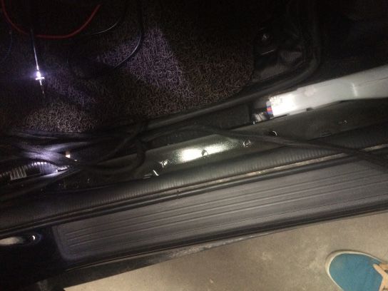
17. Using a Nylon Trim Tool, carefully disengage
the clips and remove the air-conditioners plaque
below the navigation DVD.
18. Remove the (2) screws and disengage the
claws securing the factory radio. Disconnect
any electrical connectors and remove the radio
from the dash.
19. Using the supplied T-Harness, connect to the
factory harness located behind the radio. After
making the connection, route the harness to-
wards the driver's side lower dash area.
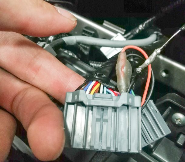
Page 10 of 1620. Locate the large wire harness up near the dash
brace. Locate the large WHITE wire within this
harness. Use the supplied splice-clip and attach
the YELLOW power wire from the Power Lift
Gate Kit to the WHITE power wire.
21. Mount front button in available factory button
location. Connect button harness to canbus
harness.
22. Begin routing the main wiring harness down the
driver's side of the vehicle, towards the control
module mounting location in the rear quarter
panel.
Page 11 of 1623. Remove the screws securing the tail lamp to
the vehicle's body. Then disengage the clips to
loosen the tail lamp assembly. Disconnect the
wiring harness, remove, and set the tail lamp as-
sembly aside where it will not be damaged.
Repeat for other side tail lamp assembly.
24. Using a helper or supporting brace, support the
lift gate in the full opened position.
25. Using a pry tool, remove the lower clip on the
end of the OEM gas support struts for the lift
gate.
Exercise caution when removing the sup-
port struts, as the lift gate is very heavy once
removed.
26. Using a pry tool, remove the upper clip on the
end of the OEM gas support strut for the lift
gate, and remove the support strut.
27. Repeat for the opposite side.
Page 12 of 1628. Install the Power Lift Gate Motors to the
facotry mounts, verifying that the clips are fully
engaged. Ensure the LEFT and RIGHT motors
are mounted on the correct sides. Then reinstall
the tail lamp assemblies, taking care to locate
the Power Lift Motor in the slot on the tail lamp
assembly.
29. Remove the tape securing the wire loom to the
tail lamp rubber wiring boot. Route the Power
Lift Gate Motor's wiring harness through the tail
lamp wiring boot, to the interior of the vehicle.
30. Once wire is completely pulled through wiring
boot, re-tape with waterproof electrical tape to
prevent water leaks.
31. Route the RH Lift Motor's wiring harness to-
wards the driver's side of the vehicle, following
the illustrated to the path. Secure to the ve-
hicle's body along the routing path.
Page 13 of 1632. Make all appropriate connections to the con- Rear Seat Release Handle Mounting Location
trol module. Then, using the supplied mounting
bracket secure the control module to the vehi-
cle's body structure in the LH rear quarter panel
area. Note the location of the rear seat release
handle for reference.
33. Disengage the claws and remove the lift gate
center trim garnish.
34. Disengage the claws and remove the lift gate
side trim garnish. Repeat for other side.
Page 14 of 1635. Remove the screw inside the pull handle. Then
carefully pry to disengage the claws and remove
the pull handle.
36. Disengage the clips and remove the lift gate
interior trim panel.
37. Route the open/close button's wiring harness
up through the OEM wire harness boot and into
the lift gate.
38. Drill a hole in the pull handle and mount the
open/close button on the left side of the handle.
Page 15 of 16THESE POINTS MUST BE CHECKED TO ENSURE A QUALITY INSTALLATION
Head Light Massage Seats (if equipped)
If the warning lights remains on, it may
indicate a system malfunction. Power Side Mirrors (if equipped)
High Beams
Side Mirror Defogger (if equipped)
Turn Signal Lights
Front Windshield Defogger (if equipped)
Tail Lights
Navigation System (if equipped)
Stop Lights
Rear Sunshade (if equipped)
Backup Lights
Cruise Control Light (if equipped)
Hazard Lights
Steering Wheel Audio Control
Marker Lights (if equipped)
HVAC
Dome/Courtesy Lights
Power Locks (if equipped)
Panel/Switch Illumination
Accessory Controls/Illumination Power Windows (if equipped)
(if equipped)
Rear Window Defogger Gauges
(if equipped)
Front Wiper/Washer
Key Sensor Buzzer
Hood Latch Release
Fog Lights (if equipped)
Day Time Running Lights Passenger Air Bag Switch (if equipped)
(if equipped)
Trunk/Tailgate/Bed Lights Rollover Side Curtain Air Bag Switch (RSCA)
(if equipped)
Glove Box Light (if equipped) Horn
ABS Light (if equipped) Seat Belt Warning Light
If the warning lights remains on, it may
Rear Wiper/Washer (if equipped) indicate a system malfunction.
Air Bag Warning Light
Clock (if equipped) If the warning lights remains on, it may
indicate a system malfunction.
Accessory Power Socket Lamp Failure Sensor
(if equipped) If the warning lights remains on, it may
Starter indicate a system malfunction.
Track/Skid Control Light (if equipped)
Audio/Video (if equipped) If the warning lights remains on, it may
indicate a system malfunction.
Tire Pressure Monitoring System (TPMS)
Power Sliding Door (if equipped)
Prior to TPMS activation and Pre-Delivery
Service (PDS) of the vehicle the TPMS light will
Convenience Memory Settings blink when IG is turned on. After TPMS activa-
(if equipped) tion and PDS of the vehicle the TPMS light will
illuminate for a few seconds and go off when IG
Heated Seats (if equipped) is turned on.
Page 16 of 16You can also read


