REACTOR IN THE HOME RANGE - 230V INSTALLATION AND MAINTENANCE MANUAL - AquaPro
←
→
Page content transcription
If your browser does not render page correctly, please read the page content below
REACTOR IN THE HOME RANGE
230V

       INSTALLATION AND MAINTENANCE MANUAL

UV_Home_(anglais) - DOC012472 - Ind. O03 - 27/04/2017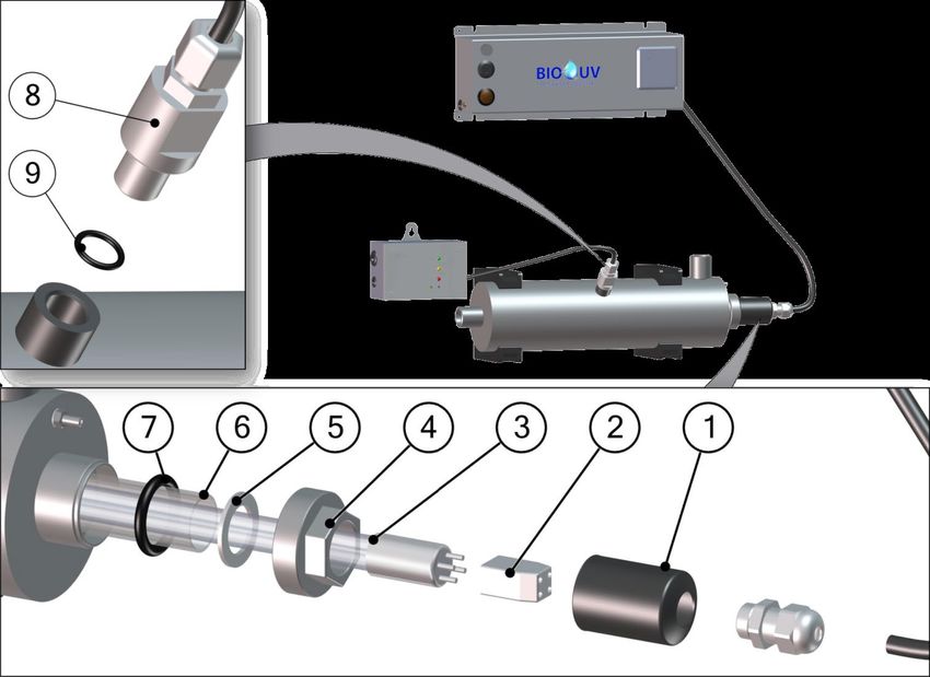
We thank you for choosing a BIO-UV reactor.
Our equipment has been designed to give you reliable and safe operation for many years to come.
According to the decree of the Health Ministry of the August 21st of 2008, concerning the case of rainwater collected on
roofs treatment, this water can not be used for human consumption.
The BIO-UV reactors have been designed for speed and ease of installation.
Their design also makes them easy to maintain.
Read these instructions carefully in order to optimize the operation of your reactor.

TABLE OF CONTENTS :
                                                                                                                                                                                                                         pages
A. Technical characteristics ................................................................................................................................................. 3
B. Safety Warnings ............................................................................................................................................................... 4
C. Installation guide ............................................................................................................................................................. 5
   1. Foreword ........................................................................................................................................................................................................................5
   2. Usage environment ....................................................................................................................................................................................................5
   3. Instructions for reactor installation ......................................................................................................................................................................5
   4. Instructions for electrical connections ................................................................................................................................................................6
   5. Filtration kit options ...................................................................................................................................................................................................7
       a.) Mounting of the 2 filters kit for HOME 2 and HOME 3 ...........................................................................................................................7
       b.) Mounting of the 3 filters kit for HOME 2 and HOME 3...........................................................................................................................8
       c.) Installation procedure ........................................................................................................................................................................................9
   6. Option UV sensor and PRO3 monitor ............................................................................................................................................................... 10
D. Starting up .................................................................................................................................................................... 11
E. Procedure to replace the lamp, the quartz sleeve and the seal ................................................................................. 12
F. Maintenance file............................................................................................................................................................ 14
G. Electrical description .................................................................................................................................................... 15
   1. Electrical unit .............................................................................................................................................................................................................. 15
   2. Wiring of an alarm contact on PRO3 monitor option ................................................................................................................................ 16
H. Blown up view with UV sensor option ........................................................................................................................ 17
I. Dimensions ..................................................................................................................................................................... 18
J. Warranties...................................................................................................................................................................... 19

UV_Home_(anglais) - DOC012472 - Ind. O03 - 27/04/2017                                                                                                                                                Copyright BIO-UV
Marque, Modèles et Brevets déposés - Produits exclusifs                                                                                                                                                        Page 2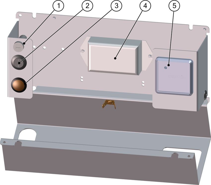
A. TECHNICAL CHARACTERISTICS
           HOME RANGE                UNIT HOME 2 -230V            HOME 3 - 230V HOME 4 – 230V HOME 6 – 230V HOME 9 – 230V
                                                                    REACTOR
Material                               -    304L stainless steel 304L stainless steel 316L stainless steel 316L stainless steel 316L stainless steel
Surface finish                         -      Mirror polished      Mirror polished Micro-blasted steel Micro-blasted steel Micro-blasted steel
Maximum operating pressure            bar            6                    6                   10                    10                   10
Weight                                kg             2                   3,1                  4,5                  6,7                  8,8
Diameter                              mm            90                    90                  90                   114                  114
Max length                            mm            446                  717                 1067                 1072                 1325
Connection type                        -      Male threaded        Male threaded        Male threaded        Male threaded        Male threaded
Connection                             -           3/4''                3/4''                 1’’                 1’’1/2               1’’1/2
Top drain                              -            No                   No                   Yes                  Yes                  Yes
Bottom drain                           -            No                   No                   No                   No                   No
Head loss (lamps are end of life,
                                      bar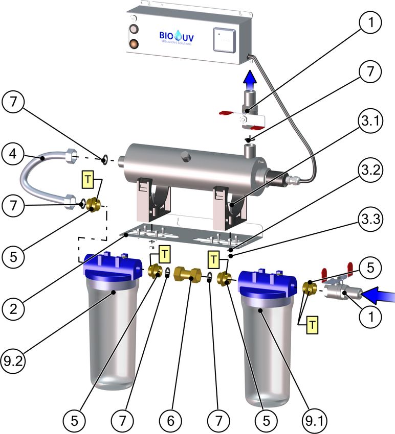
B. SAFETY WARNINGS

                                   • Switch off the device 10 minutes before any intervention to let the lamps cool down.

                                   • Stop the system in the event of a prolonged stop of the water flow

                                   • Never expose yourself to the radiation of the ultraviolet lamps when lit. This may
                                     cause severe injuries or burns and may even lead to loss of eyesight.

                                   • When the lamps are running, do not take the lamps of the reactor out or remove the
                                     protection covers

                                   • When dismounting UV lamp or quartz tube, it is necessary to wear protection gloves not
                                     to let fingerprints that could affect the UV emissions quality

                                   • Even when stopped, power is present in the electrical unit so make sure that the main
                                     power supply upstream of the electrical cabinet is switched off before carrying out any
                                     work on the equipment.

                                   • Do not use the reactor if the power supply wire is worn or damaged. In this case it
                                     should be replaced.

                                   • To avoid electric short-circuits, do not place the electric wires or the reactor in the pool
                                     water or in any other maintenance or cleaning fluid.

                                   • Do not perform electrical measurement on ballast output (risk of overvoltage)

                                   • Never unscrew the quartz tube sealing nut when the reactor is on load as the quartz
                                     tube could be blown out of the reactor with force and injure you.

                                   • In case of a microleakage, the reactor must be isolated and drained to perform
                                     maintenance as soon as possible.

                                   • Do not use the BIO-UV reactor for any other use than that for which it was designed.

UV_Home_(anglais) - DOC012472 - Ind. O03 - 27/04/2017                                                          Copyright BIO-UV
Marque, Modèles et Brevets déposés - Produits exclusifs                                                                  Page 4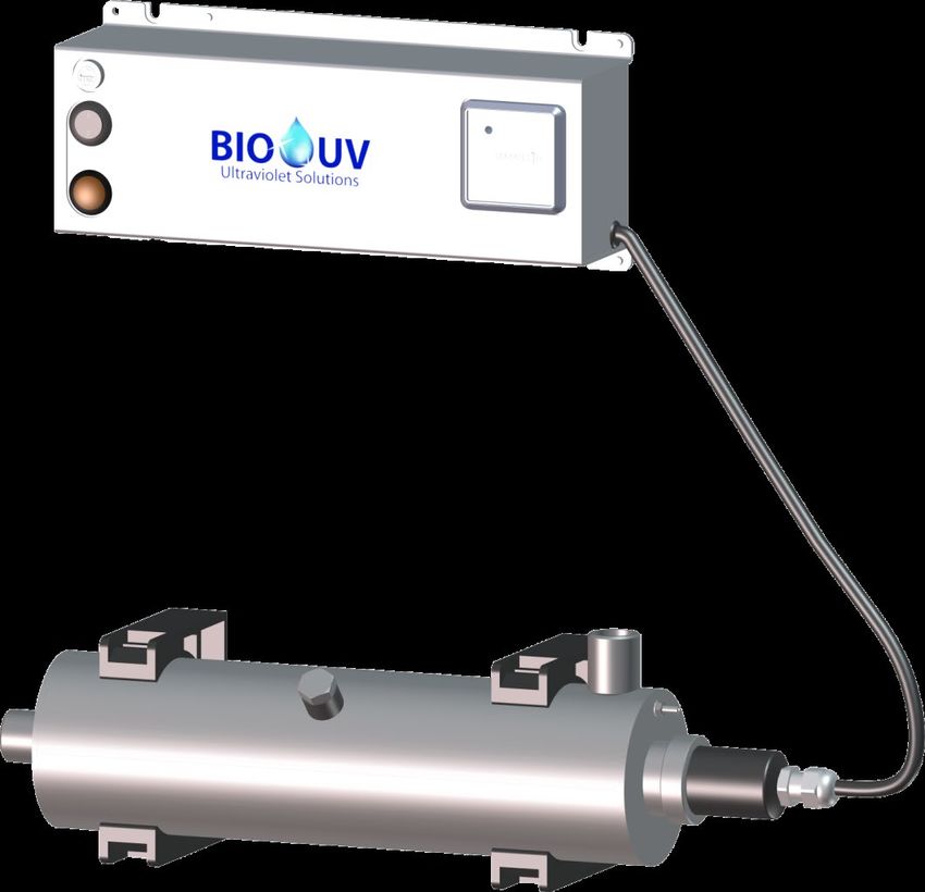
C. INSTALLATION GUIDE
       1. Foreword
                         BIO-UV reactors are ready to install, no works is required inside the reactor.

                                   It is necessary to read all the instructions in this manual before
                                                        switching on the reactor.

       2. Usage environment
Location                          Room protected from direct sunlight and bad weather
Ambient temperature               between 0°C et 40°C
Corrosive environment             Protect the electrical cabinet from any corrosive emanations (hydrochloric acid vapors, salt…)
Ambient humidity                  < 80% (dry area)

       3. Instructions for reactor installation
Ø The reactor can be installed from two different ways :
   • In vertical position (inlet downward)

UV_Home_(anglais) - DOC012472 - Ind. O03 - 27/04/2017                                                         Copyright BIO-UV
Marque, Modèles et Brevets déposés - Produits exclusifs                                                                 Page 5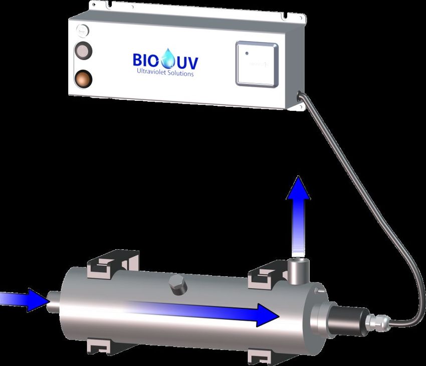
•     In horizontal position (outlet upward)

Ø It is necessary to provide a sufficient space corresponding to the reactor length to be able to bring it out of its
support easily.

Ø The reactor should be installed:
     •    as closest as possible from the water supply
     •    after a booster
     •    after a softener

                                   • The maximum pressure in the line must never be higher than the maximum operating
                                     pressure of the reactor ( see Technical characteristics, page 3)
                                   • Do not installed a by-pass between the inlet and the outlet of the reactor

        4. Instructions for electrical connections

Ø The electrical unit of the reactor is designed to be plugged directly on a wall socket (220V-16A)

UV_Home_(anglais) - DOC012472 - Ind. O03 - 27/04/2017                                                   Copyright BIO-UV
Marque, Modèles et Brevets déposés - Produits exclusifs                                                           Page 6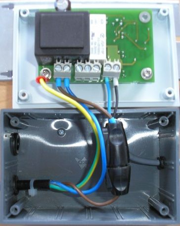
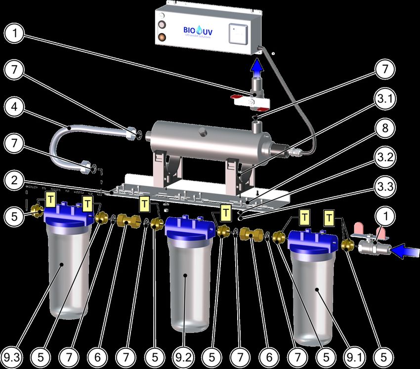
5. Filtration kit options
               a.) Mounting of the 2 filters kit for HOME 2 and HOME 3

Nr        Part code                   Designation                                                       Quantity
1         ACC006536                   Brass butterfly valve, ¾ male/female                                 2
2         PIE004433                   Filter support                                                       1
3.1       VIS004448                   UV reactor fixing screw (2 per reactor)                              2
3.2       VIS004503                   Zinc flat washer Ø6                                                  2
3.3       VIS004504                   Zinc nut Th M6                                                       2
4         ACC004439                   Hose, stainless steel                                                1
5         ACC004445                   Nipple, male/male                                                    4
6         RAC004444                   Rotary coupling                                                      1
7         JTS004442                   Fibre seal 20x27                                                     5
8         VIS004440                   Filter fixing screw (4 per filter)                                   8
9.1
          FIL004326                   Filter bowls                                                         2
9.2
T         DIV005922                   Standard Teflon roll                                                 1
                                             INSTALLATION OF CARTRIDGES IN THE FILTER BOWLS
          CAR004466                   60µ cartridge, washable , to mount on filter bowl mark 9.1           1
          CAR004467                   10µ cartridge, washable , to mount on filter bowl mark 9.2           1

UV_Home_(anglais) - DOC012472 - Ind. O03 - 27/04/2017                                              Copyright BIO-UV
Marque, Modèles et Brevets déposés - Produits exclusifs                                                      Page 7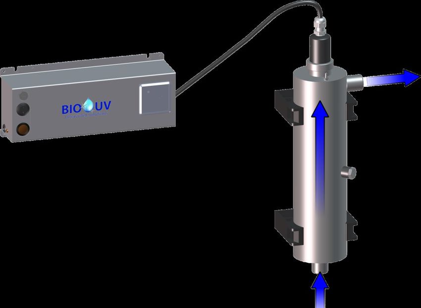
b.) Mounting of the 3 filters kit for HOME 2 and HOME 3

Nr        Part code                   Designation                                                       Quantity
1         ACC006536                   Brass butterfly valve, ¾ male/female                                 2
2         PIE004434                   Filter support                                                       1
3.1       VIS004448                   UV reactor fixing screw (2 per reactor)                              2
3.2       VIS004503                   Zinc flat washer Ø6                                                  2
3.3       VIS004504                   Zinc nut Th M6                                                       2
4         ACC004439                   Hose, stainless steel                                                1
5         ACC004445                   Nipple, male/male                                                    6
6         RAC004444                   Rotary coupling                                                      2
7         JTS004442                   Fibre seal 20x27                                                     7
8         VIS004440                   Filter fixing screw (4 per filter)                                  12
9.1
9.2       FIL004326                   Filter bowls                                                         3
9.3
T         DIV005922                   Standard Teflon roll                                                 1
                                              INSTALLATION OF CARTRIDGES IN THE FILTER BOWLS
          CAR004466                   60µ cartridge, washable , to mount on filter bowl mark 9.1           1
          CAR004467                   10µ cartridge, washable , to mount on filter bowl mark 9.2           1
          CAR004468                   Active carbon cartridge, to mount on filter bowl mark 9.3

UV_Home_(anglais) - DOC012472 - Ind. O03 - 27/04/2017                                              Copyright BIO-UV
Marque, Modèles et Brevets déposés - Produits exclusifs                                                      Page 8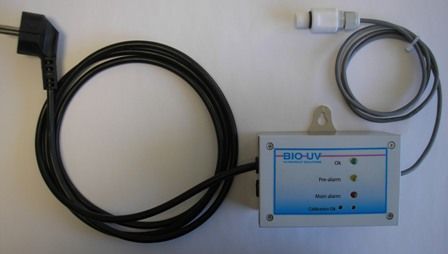
c.) Installation procedure

Nr   OPERATION
1    Assemble the filter bowls (9.1/9.2/9.3) together, with the nipples(5), the rotary coupling(s) (6), the seals (7) and Teflon
     strip (T). According the connection type, the tightening of the connections wil be done with seals or Teflon strip (see
     exploded view)

     Warning ! : Comply with the direction of water circulation in the filters, marked with arrows and the words ‘IN’ (inlet)
     and ‘OUT’ (outlet) on the filter (blue section)

2    Mount the filter support plate (2) on the filter bowls with the screws (8).

     Tip ! Before performing step 3, we advise you to mark the position of the filter support attachment on the wall.
3    Install the UV HOME reactor on the filter support:
     To do this, disengage the UV reactor from the black PVC collars
     Then screw the 2 PVC collars on to the filter support with the screws (3.1), the washers (3.2) and the nuts (3.3)
     Finally, clip the UV reactor on to the black PVC collars
4    Install the hose (4) between the outlet of the last filter and the UV HOME reactor
5    Install the 2 inlet and outlet valves (1):
          - The first on the first inlet filter
          - The second on the UV reactor outlet
6    Fix the assembly to the wall
     Connect it to the water pipe
     Check hydraulic sealing
7    Fix the electric unit of UV HOME reactor to the wall,
     Connect the power supply; perform the start-up procedure explained in paragraph D.Starting up, page 11.

UV_Home_(anglais) - DOC012472 - Ind. O03 - 27/04/2017                                                         Copyright BIO-UV
Marque, Modèles et Brevets déposés - Produits exclusifs                                                                 Page 9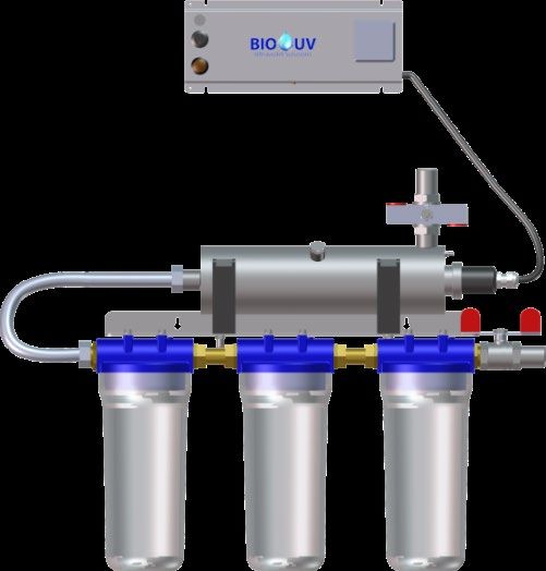
6. Option UV sensor and PRO3 monitor

The PRO3 monitor only exist in 230V to plug on a wall socket

This PRO3 monitor will indicate the drop in intensity of lamps during their lifespan and can also provide warning of fouling
of the quartz duct or the UV-C radiation measurement cell.

               Power supply cable                                                                UV sensor

                                                                                              Wall attachment
                 Monitor box Pro3                                                                 bracket

    1.    Fit the UV sensor on the reactor. If the reactor has already been installed :
               • Turn the UV lamp off
               • Cut the water supply.
               • Empty the UV reactor: Remove the drain plug
               • Carefully screw on the Teflon UV sensor in place of the drain plug. Beforehand check that the watertight
                   seal is correctly positioned
               • Take care not to twist the cable when screwing.
               • Open the water supply and check water tightness.
    2.    Attach the Pro3 UV monitor box to the wall
    3.    Connect the electrical power supply to the Pro3 Monitor box
    4.    Calibrate the UV sensor :
               • Turn the UV lamp on
               • The UV-C lamps will increase in temperature to reach maximum radiation in two to five minutes
                   (depending on the temperature of the liquid to be processed).
               • Make water flows into the reactor by slightly opening a tap (do not forget to turn it off when the sensor
                   calibration is over)
               • It is now necessary to calibrate the cell depending on the liquid to be processed :

                               CALLIBRATION of the UV-C radiation measurement cell
                        (To be carried out each time the lamp is changed and the cell is cleaned)
         1. Take a small screwdriver.
         2. SLOWLY turn clockwise the small screw located under the Main Alarm red LED, until the green
            Calibration OK LED turns on

                                                                             Adjustment
                                                                             screw

               A correct calibration is done when :
                       - The green LED (Ok) = ON
                       - The green LED (Calibration Ok) = ON

Buzzer option :
The monitor can also be provided with a buzzer that rings when an alarm is enabled (red LED is on)

UV_Home_(anglais) - DOC012472 - Ind. O03 - 27/04/2017                                                    Copyright BIO-UV
Marque, Modèles et Brevets déposés - Produits exclusifs                                                           Page 10
D. STARTING UP
1 First check the reactor and the electrical cabinet have been correctly installed (see C. Installation guide)
2 Open the water supply and check there is no leak
After the installation of the reactor BIO-UV on your installation, it can be necessary to carry out a “VACCINATION”
of the piping:
• Place a disinfectant product (for example chlorine pellets or active oxygen) preferably in the filter
3 container located upstream of the reactor.
• Leave on for 30 minutes.
• Open shortly, one by one, each draining point downstream of the system in order to fill the piping with
treated water.
Switch on the On/Off switch.
4
Check the lamp indicator is on.
5 Check hour counter is running..
6 At the first start up or when the lamp has been replaced by a new one, proceed to the sensor calibration (option).
7 Fill maintenance file (see F. Maintenance, page 14)
• The device must run without stop, 24h/24h, with hydraulic load except in the event of
a long halt of the water flow (risk of overheating and deposits on the quartz sleeve.
• It is preferable to limit the run/stop of the lamp to optimize their time of efficiency.
• If the reactor has been stop, wait 10 minutes the lamps are cooled before starting them up
to spare their lifetime.
• The lamp indicator shows that the lamp is in operation. If the lamp is operating for more
than 13000h, this should be replaced even if the lamp indicator is on.
UV_Home_(anglais) - DOC012472 - Ind. O03 - 27/04/2017 Copyright BIO-UV
Marque, Modèles et Brevets déposés - Produits exclusifs Page 11E. PROCEDURE TO REPLACE THE LAMP, THE QUARTZ SLEEVE AND THE
SEAL
Ø These operations must be carried out in case of:
• Replacement of the lamp, quartz sleeve or seal
• Checking/cleaning of the quartz sleeve
• Alarm on the PRO3 monitor (option)
The reactor MUST be SWITCHED OFF, ISOLATED, DRAINED, UNCLIPPED
1
and INSTALLED VERTICALLY
Unscrew the gland to release the lamp cable
2
remove the reactor cover
3 Dismount the lamp connector.
4 Remove the reactor from its support by making it slide through the clips.
5 Make sure that the UV lamp is cooled enough before handle it.
Remove the lamp (use the connector if necessary) and lay it on a clean and
smooth surface.
Carry out this operation carefully without touching the glass of the lamp
6
with the hands
Do not let the lamp fall into the quartz sleeve, it could break off into
the quartz sleeve and damage the quartz
Unscrew the stainless steel nut.
7
Remove the flat washer.
Remove carefully the quartz sleeve :
8 Insert a thumb or finger in the sleeve and withdraw it gently until the seal
comes free from its housing, while remaining well aligned with the axis.
Take hold of the quartz sleeve and extract it fully, making sure that you
9
keep it ABSOLUTELY well aligned with the axis.
UV_Home_(anglais) - DOC012472 - Ind. O03 - 27/04/2017 Copyright BIO-UV
Marque, Modèles et Brevets déposés - Produits exclusifs Page 12Clean the quartz sleeve with acid or white vinegar or replace it if
10
necessary.
While remaining well aligned with the axis, introduce the quartz sleeve into
the reactor to its guide at the end of the reactor.
With your finger inside the sleeve position the quartz into the spring seat at
the bottom of the reactor. A flashlight can help you to see the spring seat
11 through the quartz.
The quartz should be slightly out (from the thickness of the o-ring), it
should not be totally pushed to the bottom.
If the quartz is correctly positioned in the seat, flexibility can be felt by
pressing on it (spring effect).
Replace the o-ring :
(Mount a neaw seal at each lamp replacement)
12 • Apply water and soap on the seal,
• Position it around the quartz sleeve,
• Fully push it into its location with the nail (do not use tools).
Replace the flat washer.
13
Screw back normally the stainless steel nut with hand
Put the installation back in pressure before the reassembly of the lamp and
14
check that there is no leakage in the quartz sleeve.
Take hold of the new lamp taking care not to place your fingers outside the
cap. (if you do, clean the lamp with a soft cloth and some methylated
15
spirits).
Carefully and fully insert the lamp into the quartz tube.
16 Put back the reactor in position by sliding it through the clips.
Plug again the connectors on the lamps (Do not force : there is a way to
17
plug it).
Mount the cover.
18
Fully push the cable and tight the gland.
• Calibrate the UV-C ray measurement cell, if your device is provided with
this option at each installation of a new lamp.
19
• Take down the hour counter value at each lamp replacement because
this cannot be reset.
18 The device is ready for operation.
UV_Home_(anglais) - DOC012472 - Ind. O03 - 27/04/2017 Copyright BIO-UV
Marque, Modèles et Brevets déposés - Produits exclusifs Page 13F. MAINTENANCE FILE
CAUTION:
This sheet must be kept up to date.
It provides a record of the reactor’s operating cycle.
Date Action done by
UV_Home_(anglais) - DOC012472 - Ind. O03 - 27/04/2017 Copyright BIO-UV
Marque, Modèles et Brevets déposés - Produits exclusifs Page 14G. ELECTRICAL DESCRIPTION
1. Electrical unit
REFERENCES
HOME 2 - HOME 3 - HOME 4 - HOME 6 - HOME 9 -
MARK DESIGNATION
230V 230V 230V 230V 230V
Fuse support ELE000839 ELE000839 ELE000839 ELE000839 ELE000839
1 ELE001837 ELE001837 ELE001837 ELE001837 ELE001837
Fusible
(5x20,1A) (5x20,1A) (5x20,1A) (5x20,1A) (5x20,1A)
2 ON/OFF switch ELE000770 ELE000770 ELE000770 ELE000770 ELE000770
3 Lamp indicator ELE000817 ELE000817 ELE000817 ELE000817 ELE000817
4 Ballast BAL007134 BAL005604 BAL005604 BAL005604 BAL006995
5 Hour counter ELE000026 ELE000026 ELE000026 ELE000026 ELE000026
Fuse replacement
• If the lamp indicator is off and the counter is not running when the bow is on then the fuse must be replaced
• To replace the fuse, use a flat screwdriver and make a quarter turn to the left to open the fuse support (1)
UV_Home_(anglais) - DOC012472 - Ind. O03 - 27/04/2017 Copyright BIO-UV
Marque, Modèles et Brevets déposés - Produits exclusifs Page 152. Wiring of an alarm contact on PRO3 monitor option
The alarm contact is used to control a safety valve (no water flow), a buzzer, a
light... when the alarm is triggered on the PRO3 monitor. It supports a maximum
voltage of 230 V and a current of 1A.
The general alarm fault report is indicated by dry contacts (NO or NC) on the
monitor card in the box. The dry contacts must be supplied from the outside in
order to retrieve and send the signal.
• NO (normally open) contact connection between terminals 3 and 4.
This contact is open in alarm or in the event of a power failure and
closed when OK.
• NC (normally closed) contact connection between terminals 4 and 5. Inner view of the electronic board of
This contact is closed in alarm or in the event of a power failure and the PRO3 monitor
open when OK. The contacts are represented inactive:
monitor in alarm or power off
Example of wiring for a NC electrovalve (Normally closed)
The electrovalve must be installed in order to prevent the water flow in the event of an alarm or a power failure
12 345 67 Inner view of
the PRO3
monitor
Phase
Neutral
Electrovalve
UV_Home_(anglais) - DOC012472 - Ind. O03 - 27/04/2017 Copyright BIO-UV
Marque, Modèles et Brevets déposés - Produits exclusifs Page 16H. BLOWN UP VIEW WITH UV SENSOR OPTION
REFERENCE
MARK DESIGNATION
HOME 2 HOME 3 HOME 4 HOME 6 HOME 9
1 Nut protection VIS004279 VIS004279 USI005243 USI005243 USI005243
2 Lamp socket ElE002603 ElE002603 ELE002603 ELE002603 ELE002603
3 Lamp LPE000003 LPE000004 LPE000005 LPE000005 LPE000006
4 Sealing nut USI004134 USI004134 USI005244 USI005244 USI005244
5 Protection washer PIE000659 PIE000659 PIE000659 PIE000659 PIE000659
6 Quartz sleeve d25 QUA000016 QUA000017 QUA000018 QUA000018 QUA000019
7 O ring d25 JTS000100 JTS000100 JTS000100 JTS000100 JTS000100
8 Teflon UV sensor (Option) ELE004721 ELE004721 ELE004721 ELE004721 ELE004721
9 O ring JTS000230 JTS000230 JTS000230 JTS000230 JTS000230
Note : In standard version, UV sensor is replaced by a draining plug : ACC000410
UV_Home_(anglais) - DOC012472 - Ind. O03 - 27/04/2017 Copyright BIO-UV
Marque, Modèles et Brevets déposés - Produits exclusifs Page 17I. DIMENSIONS
F
G
H
C
D
E
A B
J J
I K K
A B C D E F G H I J K Reactor
DESIGNATION Flanges
Dimensions in mm weight (kg)
UV HOME 2 446 122 326 446 130 77 120 284 Male threaded 3/4’’ 3,5
UV HOME 3 717 122 596 717 130 77 120 284 Male threaded 3/4’’ 5
UV HOME 4 1067 159 871 1067 136 77 120 284 Male threaded 1’’ 4,8
UV HOME 6 1072 154 865 1072 160 77 120 284 Male threaded 1’’1/2 6,8
UV HOME 9 1325 155 1119 1325 158 77 120 284 Male threaded 1’’1/2 8,3
KIT UV HOME 2 /
77 120 284 152 527 532 Male threaded 3/4’’ 8
2 FILTERS
KIT UV HOME 2 /
77 120 284 152 527 708 Male threaded 3/4’’ 8,5
3 FILTERS
KIT UV HOME 3 /
77 120 284 152 527 789 Male threaded 3/4’’ 9,5
2 FILTERS
KIT UV HOME 3 /
77 120 284 152 527 844 Male threaded 3/4’’ 10
3 FILTERS
UV_Home_(anglais) - DOC012472 - Ind. O03 - 27/04/2017 Copyright BIO-UV
Marque, Modèles et Brevets déposés - Produits exclusifs Page 18J. WARRANTIES
Units in the BIO-UV range are guaranteed subject to the following conditions:
- 5 years for the stainless steel reactor (materials and welding) except in the event of use in a highly corrosive
environment (brackish or very salty, e.g.: seawater, storage near to acid and corrosive products , use of acid
hydrochloric).
Warranties exceptions:
Exceptional cases of corrosion in particular electrolytic
Damages caused by overpressure
Overtaking of the maximum operating pressure
No respect of the installation recommendations
A reactor that has run without water
Chloride concentration in water higher than 500 mg/liter.
- 2 years for all electrical components except the UV lamp (consumable).
Warranties exceptions:
Electrical components are not guaranteed against overvoltage and lightening damage
Modification and add of components within the electrical cabinet
Use of parts that don’t come from BIO-UV
No respect of the installation recommendations
A reactor that has run without water
No respect of the use and maintenance recommendations.
Caution: the quartz tube and the lamp are not guaranteed against breakage.
• Faulty parts must be returned to BIO-UV, with details of the unit type and serial number, for exchange
after technical evaluation.
• Shipping costs will be shared between the retailer and BIO-UV.
• The guarantee runs from the day of installation: this date must be notified to BIO-UV by returning the
guarantee validation form by post or fax.
Caution: If the guarantee validation form is not returned within one month following purchase of
the unit, BIO-UV will use the month and year of manufacture of the unit as the guarantee start
date.
- If the instructions for installation and use are not followed, BIO-UV cannot accept responsibility and the
guarantees will be considered null and void.
How to contact the BIO-UV Team.
Company BIO-UV SA
850, Avenue Louis Médard
34400 LUNEL France
Phone: +33 (0)4 99 133 911
www.bio-uv.com
Email : info@bio-uv.com
UV_Home_(anglais) - DOC012472 - Ind. O03 - 27/04/2017 Copyright BIO-UV
Marque, Modèles et Brevets déposés - Produits exclusifs Page 19You can also read