Reconfigurable Computing for Reactive Robotics Using Open-Source FPGAs
←
→
Page content transcription
If your browser does not render page correctly, please read the page content below
electronics
Article
Reconfigurable Computing for Reactive Robotics Using
Open-Source FPGAs
José M. Cañas 1, * , Jesús Fernández-Conde 1 , Julio Vega 1                        and Juan Ordóñez 2
                                          1   Department of Telematic Systems and Computation, Rey Juan Carlos University, Fuenlabrada,
                                              28942 Madrid, Spain; jesus.fernandez@urjc.es (J.F.-C.); julio.vega@urjc.es (J.V.)
                                          2   JdeRobot Organization, Alcorcón, 28922 Madrid, Spain; jordonezcerezo@hotmail.com
                                          *   Correspondence: josemaria.plaza@urjc.es

                                          Abstract: Reconfigurable computing provides a paradigm to create intelligent systems different from
                                          the classic software computing approach. Instead of using a processor with an instruction set, a full
                                          stack of middleware, and an application program running on top, the field-programmable gate arrays
                                          (FPGAs) integrate a cell set that can be configured in different ways. A few vendors have dominated
                                          this market with their proprietary tools, hardware devices, and boards, resulting in fragmented
                                          ecosystems with few standards and little interoperation. However, a new and complete toolchain for
                                          FPGAs with its associated open tools has recently emerged from the open-source community. Robotics
                                          is an expanding application field that may definitely benefit from this revolution, as fast speed and
                                          low power consumption are usual requirements. This paper hypothesizes that basic reactive robot
                                          behaviors may be easily designed following the reconfigurable computing approach and the state-
                                          of-the-art open FPGA toolchain. They provide new abstractions such as circuit blocks and wires for
                                          building intelligent robots. Visual programming and block libraries make such development painless
                                          and reliable. As experimental validation, two reactive behaviors have been created in a real robot

                                   involving common sensors, actuators, and in-between logic. They have been also implemented using
Citation: Cañas, J.M.; Fernández-         classic software programming for comparison purposes. Results are discussed and show that the
Conde, J.; Vega, J.; Ordóñez, J.          development of reactive robot behaviors using reconfigurable computing and open tools is feasible,
Reconfigurable Computing for              also achieving a high degree of simplicity and reusability, and benefiting from FPGAs’ low power
Reactive Robotics Using Open-Source       consumption and time-critical responsiveness.
FPGAs. Electronics 2022, 11, 8.
https://doi.org/10.3390/                  Keywords: robotics; reconfigurable computing; open-source FPGAs
electronics11010008

Academic Editor: Konstantinos
Masselos
                                          1. Introduction
Received: 24 November 2021
                                               Robotics is an exciting engineering field with recent massive applications beyond
Accepted: 20 December 2021
                                          the classic automotive and integrated circuit factories. Logistics (such as Amazon robots
Published: 22 December 2021
                                          at warehouses), food packaging, autonomous vehicles, drones for inspection, and home
Publisher’s Note: MDPI stays neutral      vacuum cleaners are just a few examples. Robots have emerged from research labs and
with regard to jurisdictional claims in   are increasingly entering into people’s actual daily life. Real-world robot applications
published maps and institutional affil-   typically require reliability and fast processing, as robot behaviors have to be robust and
iations.
                                          agile. Frequently, low power consumption is also a requirement.
                                               Generally, robots are composed of hardware and software. Sensors, actuators, and
                                          processors are the main hardware components. Sensors provide information about the sur-
                                          roundings, such as laser scanners, laser imaging detection and ranging (LIDAR), cameras,
Copyright: © 2021 by the authors.
Licensee MDPI, Basel, Switzerland.
                                          or the robot itself (battery sensors, inertial measurement units, encoders, etc.). Actuators
This article is an open access article
                                          allow the robot to perform actions, including the robot’s physical movement. Electrical
distributed under the terms and           motors are the most ubiquitous ones.
conditions of the Creative Commons             The first and most widely used method to create robot intelligence is the development
Attribution (CC BY) license (https://     of specific software. That software runs on the robot’s embedded computers and micro-
creativecommons.org/licenses/by/          controllers; it determines the machine’s behavior on its environment, goals, and reactions.
4.0/).

Electronics 2022, 11, 8. https://doi.org/10.3390/electronics11010008                                     https://www.mdpi.com/journal/electronics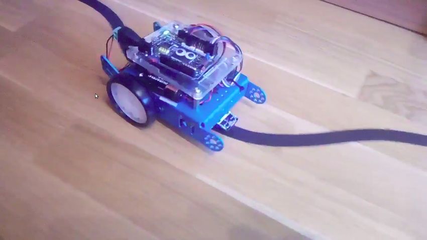
Electronics 2022, 11, 8                                                                                             2 of 17

                          It commands the onboard computer(s) to extract relevant information from sensor data,
                          make control decisions, and send commands to the robot’s actuators.
                                A second novel method is the use of reconfigurable computing, currently employing
                          FPGAs. In reconfigurable computing, the basic integration unit is not the library function
                          or subroutine but the electronic block with its inputs and outputs. Blocks and libraries of
                          existing reusable blocks make the development of data-driven applications straightforward.
                                FPGAs have been used in many application fields [1], such as digital control, com-
                          munication interfaces, networking, computer security, cryptography techniques, machine
                          learning, digital signal processing, image and video processing, big data, and computer
                          algorithms. In particular, their low price, time-critical processing, and power efficiency are
                          also beneficial in robotics.
                                Two leading vendors dominate the FPGA market: Xilinx and Intel-Altera, with more
                          or 85% of the share. They provide FPGA circuits and proprietary development tools (as
                          Vivado from Xilinx or Quartus Prime from Intel-Altera). This closed market has resulted in
                          a fragmented ecosystem and low interoperation. In the last years, a set of open tools for
                          development with FPGAs have appeared [2,3], some of them based on reverse engineering
                          of the devices from the most extended providers [4,5].
                                This paper focuses on the intersection of two fields: robotics and reconfigurable
                          computing. It shows the usefulness of recent open-source tools and FPGA computing when
                          developing robot applications, thus expanding the scope of open FPGAs beyond digital
                          electronics. They provide an easy and reliable way of creating reactive robot behaviors, with
                          some advantages over the classic programming approach. For experimental validation, a
                          commercial robot endowed with ultrasound (US) sensors, infrared (IR) sensors, and motors
                          has been employed. The intelligence of this robot for two reactive autonomous behaviors
                          (line following and obstacle avoidance) has been developed using the reconfigurable
                          computing approach, where a visual editor tool is used for circuit generation and synthesis
                          into an open FPGA board attached to the robot.
                                For the sake of comparison, the software approach, where Python programs run on
                          the robot’s microprocessor, has also been developed. In the software implementation, the
                          application is a program (a sequence of instructions); the behavior source code requires
                          an application programming interface (API) including functions to get sensor readings
                          and send actuator commands; variables are used; and the instructions are run sequentially,
                          iterating inside an infinite loop. In the hardware implementation, the application is a circuit;
                          the behaviors require a set of driver blocks that provide sensor and actuator access; the
                          blocks are interconnected through wires; and all the driver and specific logic blocks run
                          genuinely in parallel.
                                The rest of this article is organized as follows. In Section 2, we review related works in
                          the literature. In Section 3, we provide detailed background on the two different approaches
                          compared. In Section 4, we present the experimental validation, describing two basic
                          distinct reactive robot behaviors and their corresponding implementations employing the
                          reconfigurable computing and software methods. Discussion about results and analysis of
                          both paradigms’ strong and weak points are presented in Section 5. Finally, in Section 6,
                          we draw the main conclusions of this work.

                          2. Related Work
                               FPGAs have been widely used in robotics and computer vision. In robot control,
                          Alkhafaji et al. [6] review several relevant works, and the main arguments for the usage
                          of FPGAs instead of application-specific integrated circuits (ASICs) in robotics controllers
                          are exposed. For control in industrial robots, [7] is an illustrative example. The authors
                          developed an FPGA-based motion control system employing an open architecture and
                          vendor-independent control system. It was tested on a Fanuc S420F using Xilinx FPGAs.
                          Another example with industrial robots is described in [8] for Mitsubishi PA10, incorporat-
                          ing a Xilinx board. A camera served as the primary sensor for servo-ing control.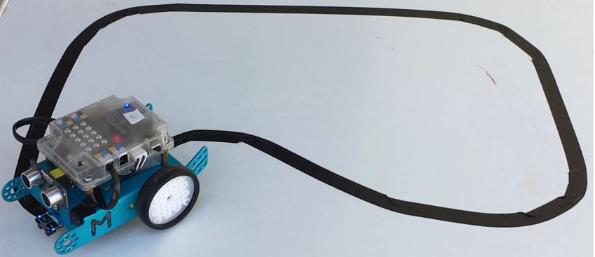
Electronics 2022, 11, 8                                                                                         3 of 17

                               Sharma et al. [9] compared several flight control approaches in small unmanned
                          aerial vehicles. FPGA/DSP(digital signal processing)-based solutions are the best in this
                          domain, as they run with low power, fast response, and less volume and weight. An
                          appealing example is PynqCopter [10], an open-source control system implemented on
                          an FPGA-based board (Xilinx PYNQ-Z1) for a hexacopter. They used high-level synthesis
                          tools. In another illustrative work, Eizad et al. [11] presented a custom hardware FPGA
                          control system capable of stabilizing the roll, pitch, and yaw of a small scale quadrotor
                          unmanned aircraft using a PD controller for each rotation axis. The practical control loop
                          rate for this FPGA (hardware approach) was 4.3 MHz, overcoming the 0.71 MHz for an
                          ARM7 microcontroller (software approach).
                               Inside the aerial robotics field, Bouhali et al. [12] provide a complete review of
                          the diverse uses of FPGAs in unmanned aerial vehicles (UAVs). They organize them
                          around three areas: high-level control, low-level control, and mission-critical tasks. High-
                          level control includes stereo vision, SLAM (simultaneous localization and mapping), and
                          path planning. Low-level control includes stability control, state estimation, interfacing
                          with sensors, and motor control. Mission-critical tasks include obstacle avoidance, object
                          recognition, and tracking and communications.
                               FPGAs have also been used for speeding up image processing inside robot applications.
                          For instance, Alabdo et al. [13] describe a complete visual pipeline on FPGA, including
                          thresholding, erosion, blob detection, and centers calculation. FPGAs have also been used
                          for more elaborate image processing, such as Harris corner detector [14], and extraction
                          and matching of scale-invariant feature transform (SIFT) keypoints [15].
                               Image processing in FPGAs has been related to the self-localization capability, which
                          is useful for robots. For instance, Rodríguez-Araujo et al. [16] present a distributed
                          FPGA-based embedded image processing system for accurate and fast simultaneous es-
                          timation of the position and orientation of remotely controlled vehicles in indoor spaces.
                          Boikos et al. [17] describe an FPGA accelerator architecture for depth estimation in SLAM
                          algorithms achieving a rate of more than 60 mapped frames/s, similar performance to that
                          of a high-end desktop CPU with power consumption improved by an order of magnitude.
                               In robot navigation and path planning algorithms, performance has also been im-
                          proved with FPGAs. For instance, Murray et al. [18] construct robot-specific circuitry
                          for motion planning, capable of generating motion plans approximately three orders of
                          magnitude faster than traditional methods. Building a probabilistic roadmap is a common
                          approach for motion planning problems, as in configuration space for industrial robots.
                          Their proposal makes collision detection circuits for the roadmap edges, which entirely
                          run in parallel to perform the path search. A second relevant example [19] implements a
                          customized genetic algorithm for a mobile robot’s path planning. A Xilinx FPGA device
                          and a Pioneer 3DX platform were used in this work.
                               In real systems, the required computing inside a robot is not exclusively executed
                          in FPGAs. They are typically combined with general-purpose CPUs or even graphics
                          processing units (GPUs) in a heterogeneous hardware–software co-design. A relevant work
                          showing this is [20], where FPGA accelerators are used for SLAM, motion planning, and
                          convolutional neural network inference. The OpenCL framework was used for program-
                          ming and executing programs across heterogeneous platforms. With FPGA acceleration,
                          the SLAM and motion planning tasks are performed 2–4 times faster than the fine-tuned
                          software implementation.
                               Reconfigurable computing has also been used in bioinspired robots, implementing
                          nonconventional computation. Quintal et al. [21] implemented a decentralized inverse
                          optimal neural controller on a shrimp robot using an FPGA in an Intel-Altera board.
                          Linares et al. [22] mimic inside a Xilinx FPGA the neural processing on some retinal cells
                          and compare it with a software approach. The visual input for these cells comes from an
                          asynchronous event-driven dynamic vision sensor. The hardware approach to this robot
                          perception task provides faster latency in the detection of visual stimuli.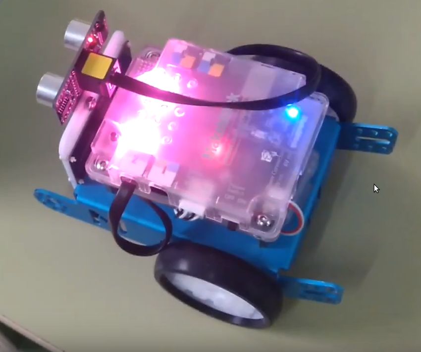
Electronics 2022, 11, 8                                                                                             4 of 17

                          Open FPGAs in Robotics
                               The Project IceStorm [23], led by Clifford Wolf, is a relevant example and aims to
                          document the bitstream format of Lattice iCE40 FPGAs and provide simple tools for ana-
                          lyzing and creating bitstream files. The Icestudio tool [24], which provides a combination
                          of Verilog and a visual language for FPGA programming, is based on IceStorm. The Symbi-
                          flow toolchain (https://symbiflow.github.io (accessed on 19 December 2021)) is another
                          powerful and illustrative example. Among other tools, it includes Yosys synthesis [25–27],
                          Project IceStorm, Project X-Ray for documenting the Xilinx 7-series bitstream format, and
                          Project Trellis for Lattice ECP5 bitstream.
                               The open toolchain for FPGAs is relatively recent; therefore, there is a lack of literature
                          showing its potential in the robotics field. Nevertheless, some recent works already use
                          open FPGAs in robotics. For instance, Caro et al. [28] present a new approach inspired in
                          the animal nervous system for controlling a hexapod robot. It implements the binomial
                          brain–peripheral nervous system (CNS-PNS), combining microprocessors for the high-level
                          control and FPGAs for the low-level control. Central pattern generator signals coordinate
                          the motion of all of the legs for robot walking; they are translated into Verilog, synthesized,
                          uploaded, and run into a Lattice iCE40 FPGA, all on-demand in real time. To create the
                          required FPGA digital control circuits, the open-source tools Icestudio [24] and Apio [29]
                          were used.
                               A self-balancing robot that solves the inverted pendulum control problem has been
                          successfully programmed using FPGAs’ open toolchain. Ordoñez et al. [30] developed a
                          perception module for an inertial sensor, a proportional–derivative controller, and a driver
                          module for two DC motors. The system includes an Arduino microcontroller for the sensor
                          driver and an IceZum Alhambra board (which integrates an iCE40 FPGA from Lattice) as
                          the primary computing unit. All of the FPGA modules were developed using Icestudio.
                               The present work constitutes a step forward from this self-balancing robot’s previous
                          work solving the inverted pendulum problem with open FPGAs, demonstrating that
                          reconfigurable computing with recent open FPGA tools is an easy, cost-effective, and
                          reliable approach to develop complete reactive robot behaviors involving sensors and
                          actuators.

                          3. Implementation of Intelligent Robot Behaviors
                                It is widely accepted that intelligent robots should show reactivity to the environment
                          and unexpected situations, orientation toward their goals, and some planning capability.
                          They are composed of sensors, actuators, and some logic in between. Many proposals and
                          paradigms have emerged in the last 60 years to make intelligent machines [31] and develop
                          that internal logic. There is no universal way of facing this complex task.
                                Classical symbolic AI reasoning was prevalent until the 1980s in robotics; its sense–plan–
                          act (SPA) paradigm included the perception, modeling, planning, task execution, and motor
                          control steps, with plenty of symbolic deliberation and plans. In contrast, pure reactive
                          architectures followed the faster sensing–action loop, but they did not scale to complex
                          problems. Behavior-based robotics proposed a combination of several processing units
                          with some arbitration mechanisms.
                                The subsumption architecture from Rodney Brooks [32], implemented as a distributed
                          and connected collection of hardware-specific processing units, was influential. Hybrid ap-
                          proaches are also successful in real robots—for instance, three-layer architectures, typically
                          including a deliberative layer, an intermediate executive layer, and a reactive layer, with a
                          collection of many basic behaviors that may be disabled at will. Each school of thought has
                          its advantages and weaknesses.
                                Most of these architectures are software-based and, despite their differences, they
                          share some points in common, such as running on von Neumann computers. The main
                          features of the development process of building robot intelligence from the software and
                          the hardware approaches will be examined in this section.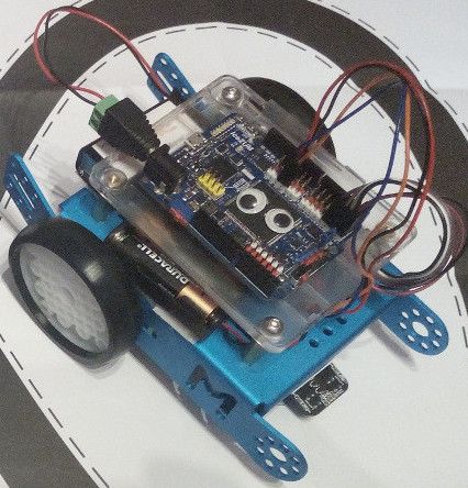
Electronics 2022, 11, 8                                                                                            5 of 17

                          3.1. Software Approach: Robot Programming
                                Developing robotics software is the traditional way of creating intelligent robots. It
                          is flexible, as detected bugs or errors may be solved by changing the source code and
                          rerunning it on the robot.
                                Embedded software developed to be run in robots has several requirements that make
                          it unique. Usually, it has to meet real-time operation and be robust because it is connected
                          to real devices. For instance, it may be driving an autonomous car at 120 km/h.
                                Robots may be programmed using many languages, including low-level languages
                          such as assembly code and high-level languages such as C/C++ or Python. C or C++ source
                          code requires a compilation to translate it into machine code and linkage with libraries
                          to build the executable program. Software development toolchains help in that. Python
                          source code needs an interpreter or runtime environment to be executed.
                                Many concepts from software engineering have been introduced in the last decade
                          into robotics software development. Currently, object-oriented programming and standard
                          interfaces are commonplace.
                                Robotic systems are usually complex, and software is customarily organized into
                          different layers. At the bottom level, there are drivers for the sensors and actuators. Above
                          those, there are controllers, reactive behaviors, and finite state machines (FSMs). More
                          sophisticated robot applications may also include a planning and task decomposition layer.
                          As previously mentioned, many cognitive architectures have been proposed over the years
                          to organize robot intelligence, perception capabilities, and decision-making. In the end,
                          they are finally implemented using some software architecture.
                                Several middlewares and frameworks have appeared to simplify and speed up the
                          development of robot applications. They favor the portability of these applications between
                          different robots, facilitating code reusability and integration. They provide: (i) a particular
                          software architecture for robot applications, such as an object collection or a set of modules
                          talking through the network or an iterative process calling to functions, or an event loop
                          with callbacks; (ii) a hardware abstraction layer that hides the complexity of accessing
                          heterogeneous hardware (sensors and actuators) under standard interfaces; (iii) many tools,
                          libraries, nodes, or common functionality stacks that can be reused in new developments
                          instead of building each new application from scratch.
                                Robot Operating System (ROS) [33,34] is one of the most popular frameworks currently.
                          It has a growing user and developer community, and its site hosts an extensive collection
                          of hardware drivers, algorithms, and other tools. ROS-based applications have several
                          communicating components (nodes) that exchange messages mainly in publish–subscribe
                          fashion (topics).
                                Several abstractions are available for robot software programmers, such as libraries
                          with reusable functions, threads, processes, object orientation, events, and messages. In
                          the lowest level, robot programs run on general purpose processors (GPUs) based on the
                          von Neumann architecture: a CPU, memory, buses, etc. The central processor supports a
                          machine instruction set and includes fetching and decoding instructions and fetching data
                          stored in RAM. Ultimately, the robot program can be seen as an instruction stream. The
                          robot’s microprocessor executes it mainly sequentially, except for some branches, loops,
                          and jumps.
                                In order to increase performance, other computer architectures such as multicore
                          computers with several CPUs or even massive parallel computers with GPUs have been
                          used. For instance, GPUs speed up computer vision operations. Most widely used neural
                          networks frameworks, such as TensorFlow or PyTorch, include the possibility of running
                          their neural models on GPUs, resulting in a performance boost.

                          3.2. Hardware Approach: Reconfigurable Computing
                               Another approach to building intelligent machines is to design an electronic circuit
                          that performs the required sensors readings, data processing, computing, decision making,
                          and actuators commanding. ASICs are circuits customized for a particular use. They are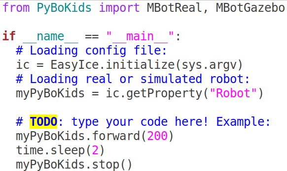
Electronics 2022, 11, 8                                                                                            6 of 17

                          widely used in environments where machine tasks are repetitive and for high-volume
                          productions. Their execution is high-speed, and they have low energy consumption, being
                          also power-efficient. However, they provide no flexibility; once the circuit has been built, it
                          may not be changed. Their redesign has high nonrecurring engineering costs.
                                In contrast to ASICs, general-purpose programmable logic devices as FPGAs are inte-
                          grated circuits designed to be configured by a customer or a designer after manufacturing.
                          They are an example of reconfigurable computing and combine some of the flexibility of
                          software computing with the high performance of the hardware approach.
                                FPGAs contain an array of programmable logic blocks, a hierarchy of reconfigurable
                          interconnects, and several discrete components such as block RAMs, DSP slices, processor
                          cores, and various communication cores [35]. The interconnections allow configuring gate
                          sets to perform complex combinational functions or simple logic gates (like AND and XOR).
                          The particular configuration determines the circuit behavior.
                                The development process in reconfigurable computing includes several steps [36–39]
                          and tools. The hardware may be designed at varying abstraction levels, usually gate level,
                          register–transfer level (RTL), and algorithmic level.
                                First, an FPGA structure and behavior is formally described in a hardware description
                          language such as Verilog, VHDL, or recent ones such as SpinalHDL. They are text languages
                          that also allow the automated analysis, verification, and simulation of the electronic circuit.
                          This text file can be seen as the source code of a particular application in reconfigurable
                          computing.
                                Second, with a logic synthesis tool, the HDL file is synthesized into a netlist. The
                          netlist is a specification of electronic components and their interconnections, considering
                          the particular target FPGA’s physical and timing constraints.
                                Third, in the place and route step, all the electronic components, circuitry, and logic
                          elements involved in the proposed “program” are placed in the limited amount of space of
                          the target FPGA. Routing decides the exact design of all the wires needed to connect the
                          placed components.
                                Fourth and last, a bitstream is generated, describing the configuration data to be
                          loaded into the physical FPGA device. When loaded, the FPGA is ready to execute. Its
                          detailed format for a particular FPGA is typically proprietary to the vendor.

                          4. Experimental Validation
                               In this section, several experiments are presented using a low-cost robotic platform
                          endowed with US sensors, IR sensors, and motors. We have implemented two reactive
                          autonomous robot behaviors under the reconfigurable computing approach, using a visual
                          editor tool for graphic circuit generation and synthesis to configure an open FPGA board
                          attached on top of the robot. Both reactive behaviors have also been developed under
                          the software approach, using Python programs running on the robot’s microprocessor to
                          establish a qualitative analogy and quantitative comparison between the two methods.

                          4.1. Robot Body: Hardware Platform
                              An Arduino-based robot, the MakeBlock mBot (https://makeblock.es (accessed on 19
                          December 2021), Figure 1 left), has been selected as the reference hardware platform. The
                          mBot, with its Arduino Uno microcontroller board, can be connected to common US/IR
                          sensors and motors used in educational robotics. It is affordable, mechanically compact,
                          and extensible.
                              The robot hardware in its original form from the factory includes the following elements:
                          •    an ATmega328P, 8-bit, low power AVR microcontroller. Its clock frequency is 20 MHz.
                               It integrates internal SRAM (2 KB).
                          •    a Me IR Receiver, which has four pins: (1) DAT, (2) RX, (3) VCC, and (4) GND. Its
                               receiving frequency is 38 kHz, and the baud rate is 9600.
                          •    a Me Ultrasonic Sensor has three pins: (1) GND, (2) 5 V, and (3) SIG. Its ultrasonic
                               frequency is 42 kHz, and it supports a 30-degree measurement angle.
Electronics 2022, 11, 8 7 of 17
• two TT Geared Motors, which work on DC 6V/200RPM. These motors support both
positive and negative transfer and no-load speed.
Figure 1. mBot robot: with original Arduino board (left) vs. with IceZum Alhambra FPGA board (right).
In the software approach, the mBot has not been modified at all. Its microcontroller
is in charge of executing the programs developed for each desired behavior. On the other
hand, we have disconnected the Arduino board and replaced it with the IceZum Alhambra
FPGA board for the reconfigurable computing approach (Figure 1 right).
The IceZum Alhambra FPGA board (https://alhambrabits.com/alhambra/ (accessed
on 19 December 2021), Figure 2) incorporates a low-cost, low-power open FPGA (Lattice
iCE40HX1K), with a base clock frequency of 12 MHz. This FPGA includes the following
hardware resources:
• 1280 logic cells (Look-Up Tables (LUTs) + Flip-Flops (FFs))
• 96 programmable I/O pins (PIOs)
• 16 RAM4K memory blocks (BRAMs)
• 160 programmable logic blocks (PLBs)
The IceZum Alhambra has been designed using open-source tools, and it is compatible
with the open-source Icestorm FPGA toolchain.
Figure 2. IceZum Alhambra FPGA board.
4.2. Reconfigurable Computing Brain: IceZum Alhambra FPGA and Icestudio
Icestudio is an open-source and multiplatform graphic editor for open FPGA boards.
It is built on top of the Icestorm project that implements the toolchain for reconfigurable
computing on open FPGAs. It supports several boards, including the IceZum Alhambra.
With Icestudio, circuits are designed graphically, connecting individual blocks of
hardware through wires. A block is an entity with input and output ports, parameters, and
some content (functionality). An example is shown in Figure 3.Electronics 2022, 11, 8 8 of 17
Figure 3. Circuit design example using Icestudio visual editor.
Icestudio provides many basic blocks, including combinational gates (AND, OR, NOT,
etc.), combinational circuits (multiplexers), and sequential elements (flip-flops, prescalers,
debouncer). Verilog language fragments can be incorporated into the design as new
blocks to implement more elaborate components (such as comparators, decoders, counters,
memories, buffers, shift registers). Icestudio supplies several blocks useful for debugging
purposes, such as elementary input devices (switches, constant-value ports) and output
devices (LEDs).
Additional Icestudio blocks have been developed to read measurements from the
sensors and generate proper pulse width modulation (PWM) signals to operate the motors
of the mBot.
4.3. Software Brain: Arduino Processor and Python Programming
Arduino is commonly programmed using the Arduino IDE or the block-based Scratch
programming language, or some variants such as mBlock (https://www.mblock.cc/en-us/
(accessed on 19 December 2021)). Python was chosen here as the programming language
because of its simplicity and expressive power. It is a text-based, object-oriented, and
interpreted language. Python has a shallow learning curve, as opposed to the Arduino
language (similar to C/C++), and at the same time, it integrates many powerful features
and libraries.
As the Python language is not supported by the manufacturer of the mBot, an entire
infrastructure was created around the PyBoKids library ([40]). The Arduino Uno micropro-
cessor is excessively limited to run an onboard Python interpreter. Therefore, a module for
the real robot, called realMBot was implemented and programmed as a Python library that
runs on the computer and communicates continuously (via USB or Bluetooth 2.4 G) with
the physical mBot robot using the Firmata protocol (https://github.com/firmata/protocol
(accessed on 19 December 2021)). An intermediary program is executed on the native
Arduino firmware (Figure 4) to support that communication.Electronics 2022, 11, 8 9 of 17
The PyBoKids library was developed to provide the application programming in-
terface (API), PyBoKids.py (https://gitlab.etsit.urjc.es/jmvega/PyBoKids/blob/master/
PyBoKids.py (accessed on 19 December 2021)) for robot applications. Its clear and natural
interface includes methods to read the measurements from the sensors and to command
the actuators of the mBot (Table 1).
Figure 4. Software robot brain in Python.
Table 1. PyBoKids.py application programming interface.
Actuators Sensors
move (V, W) readLightLevel
forward (V) readUltrasound
backward (V) readSoundLevel
left (W) readPotentiometer
right (W) readRemoteIR
stop
moveServo (θ)
ledOn
ledOff
writeText (T)
playTone (Fs)
Figure 5 shows an example program developed in Python language using the Py-
BoKids library’s API.
Figure 5. Python example program using PyBoKids library API.
4.4. Reactive Robot Behaviors
In the associated literature, several recurring basic reactive behaviors can be found
in different robotics environments. The most popular is the line follower robot ([41–44]).
A line follower robot has to follow a dark-colored line on a white-colored ground (or vice
versa). Normally, the robot incorporates two IR sensors pointing to the ground, which will
detect a white surface (high voltage) or a dark surface (low voltage).
Another standard behavior is obstacle avoidance ([42,43]). The robot has an ultrasonic
sensor that allows it to measure the distance to objects that may interfere with the robot’s
forward movement. Upon obstacle detection, the robot shall command its motors to stop,
go backward, and then turn left/right, in order to avoid the obstacle.Electronics 2022, 11, 8 10 of 17
4.4.1. Line Following Robot Behavior
In the reconfigurable computing approach, the circuit shown in Figure 6 has been
designed, connecting the output of each IR sensor to its corresponding motor in order to
activate it according to the IR sensor reading. Icestudio blocks to generate PWM signals
that set the speed of motors have been included.
Figure 6. IceStudio circuit for Line Following behavior.
The FPGA hardware resources utilized in this design are the following: FFs: 24/1280
(1.9%), LUTs: 124/1280 (9.7%), PIOs: 15/96 (15.6%), PLBs: 33/160 (20.6%), BRAMs: 0/16
(0%).
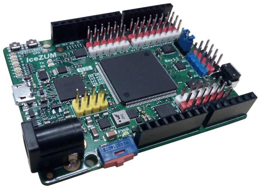
The hardware-based line follower mBot in action is shown in this publicly available
video https://www.youtube.com/watch?v=GJkRy0zWMI4 (accessed on 19 December
2021) .
In the software approach, the code developed to implement this behavior is short,
thanks to the utilization of the PyBoKids library, as shown in Listing 1.
Listing 1. Source code of line following behavior software implementation.
from lib.mBot import *
if __name__ == ’__main__’:
robot = mBot()
vel = 0.2 # meters per sec
vel_turn = 0.5 # radians per sec
while True:
IRval = robot.readRemoteIR()
if IRval == 0: # left black/ right black
robot.forward(vel)
elif IRval == 1: # left black/ right white
robot.left(vel_turn)
elif IRval == 2: # left white/ right black
robot.right(vel_turn)
elif IRval == 3: # left white/ right white
robot.stop()
time.sleep(0.2)Electronics 2022, 11, 8 11 of 17
The software-based line follower mBot in action is shown in this publicly available
video: https://www.youtube.com/watch?v=_81_cAOjJkI (accessed on 19 December 2021).
Pictures of the line following mBot robot behavior using the reconfigurable computing
approach and the software approach can be seen in Figure 7.
Figure 7. mBot robot following a line with a reconfigurable computing brain (left) vs. with a software
brain (right).
4.4.2. Obstacle Avoidance Robot Behavior
The reconfigurable computing approach corresponds to the circuit shown in Figure 8.
A US sensor driver block has been designed, providing a 16-bit number as an output
representing the elapsed time between the ultrasonic signal sent and the echo received.
This number is compared to a threshold (1000 microseconds, equivalent to an object distance
of 17 cms) using a comparator block, setting its output to a high value when the elapsed
time is less than 1000 microseconds.
Figure 8. IceStudio circuit for obstacle avoidance behavior.
This signal is connected to the input of a Moore FSM, implemented employing a
Verilog-based block. This FSM can be represented as shown in Figure 9:
Figure 9. FSM block diagram.
The three FSM outputs will control the motors (activation of left/right motor and mo-
tors’ direction). Values for output signals from FSM are given in Table 2. Timeouts forElectronics 2022, 11, 8 12 of 17
STOP_COUNT_REACHED, MOVE_BACK_COUNT_REACHED, and TURN_LEFT_COUNT
_REACHED signals have been all set to 1 s.
Table 2. Values for FSM output signals in each state.
MOTORS DIR LEFT MOTOR RIGHT MOTOR
WAIT OBSTACLE 1 1 1
STOP 1 0 0
MOVE BACK 0 1 1
TURN LEFT 1 0 1
The FPGA hardware resources utilized in this design are the following: FFs: 57/1280
(4.5%), LUTs: 218/1280 (17%), PIOs: 17/96 (17.7%), PLBs: 48/160 (30%), BRAMs: 0/16 (0%).
The hardware-based obstacle avoidance mBot in action is shown in this publicly
available video: https://www.youtube.com/watch?v=y2m9RiUH6tU (accessed on 19
December 2021).
The source code developed to achieve this behavior in the software approach is shown
in Listing 2. When an obstacle is detected at a distance less than 20 cm, the mBot is
commanded to stop, go backward for one second, turn to the right for a random amount of
time (between 0.5 and 3 s), and then continue moving forward.
Listing 2. Source code of obstacle avoidance behavior software implementation.
import random
from lib.mBot import *
if __name__ == ’__main__’:
robot = mBot()
vel = 0.5 # meters per sec
vel_turn = 0.2 # radians per sec
while True:
USval = robot.readUltrasound()
if (USval < 20):
robot.stop()
time.sleep(0.5)
robot.backward(vel)
time.sleep(1)
robot.right(vel_turn)
time.sleep(random.uniform(0.5,3))
else:
robot.forward(vel)
time.sleep(0.2)
The software-based obstacle avoidance mBot in action is shown in this publicly avail-
able video: https://www.youtube.com/watch?v=k-U7OTFT6Rs (accessed on 19 December
2021).
4.5. Quantitative Analysis
In order to evaluate quantitatively the performance of both reconfigurable computing
and software approaches, we have used the following two metrics:
• total power consumption of the system
• response time, interpreted as the minimum time needed to react to external changes
For the quantification of the total power consumed, current was measured using a
digital power supply. The voltage was always set to 3.7 volts. Results are summarized in
Table 3.Electronics 2022, 11, 8 13 of 17
Table 3. Power consumption for reconfigurable computing and software approaches.
Robot Behavior Board Idle Motors Running
Line following Arduino 250 mW 850 mW
Line following Alhambra 35 mW 635 mW
Obstacle avoidance Arduino 250 mW 850 mW
Obstacle avoidance Alhambra 38 mW 638 mW
With respect to the response time analysis, results are detailed in Table 4. In the case
of the Alhambra board, results have been obtained by circuit analysis, taking into account
hardware design constraints and maximum operating frequency of sensors (38 KHz for the
IR sensor and 42 KHz for the US sensor). For the Arduino board, we decreased sleep time
in the software programs (nominal value is 200 milliseconds, see Listings 1 and 2) until the
robot behavior was erratic.
Table 4. Time response for reconfigurable computing and software approaches.
Robot Behavior Board Response Time
Line following Arduino 10 ms
Line following Alhambra 0.033 ms
Obstacle avoidance Arduino 20 ms
Obstacle avoidance Alhambra 0.1 ms
5. Discussion
The experimental validation just presented addresses the implementation of two basic
reactive behaviors in an autonomous robot using two different perspectives: first, the
reconfigurable computing approach, where an FPGA is configured with a circuit designed
using an open toolchain visual editor for FPGAs, and second, the classic and widely used
software computing approach, where the sensors are read and actuators are commanded
by a Python software program running on a general-purpose microprocessor. They both
have proved to be satisfactory solutions for simple reactive behaviors.
A qualitative comparison of both approaches’ features and concepts is shown in
Table 5. Their various strong and weak points make them less or more suitable for develop-
ing more sophisticated robot behaviors.
Table 5. Qualitative comparison between software computing and reconfigurable hardware
computing.
Software Computing Reconfigurable HW Computing
Instruction stream Parallelism
Abstractions Physical mapping
Functions, with input parameters and result Hardware blocks, with inputs and outputs
Variables Signals
Reusable libraries Reusable blocks
Iterations (ms.) Continuous (ns.)
Temporal reasoning Spatial reasoning
Parallelism achievable with threads or pro-
Natively parallel
cesses, time multiplexing
Natively sequential Sequences achievable with states
Software computing means developing an application using a programming language
and executing it in a generic microprocessor. There are many IDEs, languages, and softwareElectronics 2022, 11, 8 14 of 17
libraries already available for developers. Even frameworks and ecosystems such as
ROS [33,34].
Reconfigurable computing means designing a hardware circuit (which can be accom-
plished using a visual editor, an HDL, or high-level synthesis (HLS), among others) and
configuring an FPGA with it. Until now, the proprietary FPGA toolchains have dominated
the market in the last decades, but recently, a completely open-source toolchain was devel-
oped. The open-hardware community is significantly improving it, expanding the set of
supported FPGA boards and circuits. It started with low-end FPGA boards, and support
for middle-end ones is almost ready. There are not many ready-for-use basic block libraries
yet, but they are growing exponentially due to the increasing number of users and the open
philosophy dynamics.
In the software approach, the reusable functionalities are provided through functions
as a sequence of instructions, and they may have input arguments and provide a result.
These functions are usually time-blocking, as the execution is natively sequential. There are
other software approaches such as event-based programming and exceptions, but they are
not the general approach. For instance, the robot.readRemoteIR() in Listing 1 is invoked
to get IR sensor measurements. If that function took 2 s to run, the following instructions
would not be executed until then. The robot.forward(vel), robot.left(vel_turn), and
robot.right(vel_turn) are called to command speed of the robot motors. For combined
functionality, functions may call to other functions to implement their own functionality.
In the hardware approach, the reusable functionalities are provided through blocks,
which are implemented in a hardware description language, with input and output signals.
These blocks run continuously, updating their outputs from the data in their inputs at
hardware speed, and their execution is natively parallel (they are non-time-blocking). For
instance, in Figure 6, the IR_right and IR_left blocks provide sensor measurements and
the LEFTmotor and RIGHTmotor blocks continuously send commands to the robot motors. A
block may be implemented with a new circuit containing other blocks and internal wires for
combined functionality. Reusing blocks speeds up the development process and increases
reliability, as those library blocks usually have been previously debugged and tested.
Variables are the natural place to hold information in the software approach. For
instance, vel_turn or vel in Listing 2. They can be read or written with new content. In
the hardware approach, signals are used, such as those on Figure 8. Constant values may
also be used in circuits, such as vel RIGHT and vel LEFT in Figure 8.
The line-following and obstacle avoidance robot behaviors with software brain work
with a single thread that runs iterations inside an infinite loop (the while True loop in
Listings 1 and 2). If more activity sources are required, the software approach may use
several threads, processes, or nodes inside the robot application, in the same computer
(or in others if available). In the same computer, (pseudo)parallelism is easily obtained
from the operating system with time multiplexing or multicore capabilities. Complex robot
applications usually involve several interacting nodes that continuously exchange messages
through a communication layer. That is the paradigm for typical ROS applications, for
instance.
There is no thread at all in the hardware brains for the same behaviors, neither any
idea of iteration: all the blocks work continuously inside the FPGA, always running in
parallel. This fact speeds up the reaction time to changes or events, improving the behavior
performance as the feedback loop becomes faster. In case some sequence is required, it may
be implemented as an FSM in the hardware approach, such as the FSM block in Figures 8
and 9. Changing that FSM to integrate a new step in the sequence can be more complicated
than in the software approach, where this can be achieved by adding some more lines to
the instructions sequence.
Regarding the data obtained in the quantitative analysis, the FPGA-based solution
clearly outperforms the CPU-based solution, both in terms of power consumption and also
in terms of response time.Electronics 2022, 11, 8 15 of 17
The reasons for the low consumption can be found mainly in that the FPGA uses
the hardware resources strictly necessary to achieve the desired behavior. Concerning the
response time, the parallelism inherent in the hardware solution makes the system react
much faster to changes in the environment in these particular robot applications.
6. Conclusions
This paper’s main conclusion is that reconfigurable computing with recent open FPGA
tools is an easy, cost-effective, and reliable approach to develop complete reactive robot
behaviors involving sensors and actuators. As experimental validation, the line-following
and the obstacle avoidance reactive behaviors have been successfully implemented in a
commercial mBot robot using the open FPGA IceZum Alhambra board and Icestudio visual
editor.
So far, the available FPGA development tools were proprietary and required advanced
knowledge to use this technology. The situation is changing; the availability of open recon-
figurable hardware boards at an affordable cost and the appearance of open tools that allow
their use in a simple fashion provide new possibilities. The open development framework
used includes: (a) reconfigurable open hardware board, (b) open tools supporting the
design and synthesis of circuits for these boards using a simple visual language, and (c)
driver blocks that simplify the reading of robot sensors (US and IR) and the control of robot
actuators (motors). Within this framework, the robot application is a circuit synthesized
in the FPGA, including the driver and custom blocks implementing the behavior’s logic
(interconnected together through signals). In this way, the design of robot applications as
circuits is granted, following the hardware-thinking principles instead of programs that
follow the software-thinking ones.
Both software and hardware approaches have proved to be valid for basic reactive
robot behaviors. Their general underlying principles and potentials have been summarized
and compared. They have distinct features, weak and strong points for developing reactive
robot applications, which have been analyzed. We envision the development of hybrid tools
that allow hardware and software co-design to materialize robotics intelligence. They shall
combine software programs (running on a computer) and hardware circuits (synthesized in
an FPGA), interacting and cooperating among them to implement smart robots’ capabilities.
In addition, we measured the power consumption and response time of both the CPU
and the FPGA-based brains. The power efficiency advantage of reconfigurable computing
can undoubtedly be helpful in resource-limited robots such as drones. Its inherent paral-
lelism will help to increase reactiveness in complex robot applications involving several
tasks in parallel.
As a future extension of this work, we intend to face more complex robot behaviors
with the reconfigurable computing toolchain. These include computer vision tasks and
behavior-based systems involving several reactive behaviors that can be dynamically
disabled at run time on purpose in some situations. The mBot robot could be replaced with
a Raspberry Pi board-based robot (such as the GoPiGo), which may easily incorporate a
USB camera.
Author Contributions: Conceptualization, J.M.C., J.V., J.O., and J.F.-C.; funding acquisition, J.M.C.;
investigation, J.M.C., J.V., J.O., and J.F.-C.; methodology, J.V.; project administration, J.M.C.; resources,
J.M.C.; software, J.M.C., J.V., J.O., and J.F.-C.; supervision, J.M.C.; validation, J.O., and J.F.-C.; visual-
ization, J.O., and J.F.-C.; writing—original draft, J.V.; writing—review and editing, J.O., and J.F.-C. All
authors have read and agreed to the published version of the manuscript.
Funding: This research was partially funded by the Community of Madrid in the framework of two
research projects: (1) Multiannual agreement with Rey Juan Carlos University in line of action 1,
“Encouragement of Young Ph.D. Students Investigation” project ref. F664, acronym UNIBOTICS2.0,
and (2) RoboCity2030-DIH-CM (2019-2022): RoboCity2030-Madrid Robotics Digital Innovation
Hub, Programa de Actividades de I+D entre Grupos de investigación de la Comunidad de Madrid
en Tecnologías 2018 project ref. S2018/NMT-4331; and by the Spanish Ministry of Economy and
Competitiveness through the RETOGAR project ref. TIN2016-76515-R.Electronics 2022, 11, 8 16 of 17
Acknowledgments: The authors thank Google for funding the JdeRobot nonprofit organization in
its calls for Google Summer of Code 2015, 2017, 2018, 2019, and 2020.
Conflicts of Interest: The authors declare no conflict of interest.
References
1. Ruiz-Rosero, J.; Ramirez-Gonzalez, G.; Khanna, R. Field Programmable Gate Array Applications—A Scientometric Review.
Computation 2019, 7, 63. [CrossRef]
2. Romanov, A.; Romanov, M.; Kharchenko, A. FPGA-based control system reconfiguration using open source software. In
Proceedings of the 2017 IEEE Conference of Russian Young Researchers in Electrical and Electronic Engineering (EIConRus), St.
Petersburg and Moscow, Russia, 1–3 February 2017; IEEE: Piscataway, NJ, USA, 2017; pp. 976–981.
3. Yu, H.; Lee, H.; Lee, S.; Kim, Y.; Lee, H.M. Recent advances in FPGA reverse engineering. Electronics 2018, 7, 246. [CrossRef]
4. Celebucki, D.; Graham, S.; Gunawardena, S. Reversing a Lattice ECP3 FPGA for Bitstream Protection. In Proceedings of the Inter-
national Conference on Critical Infrastructure Protection, Arlington, VA, USA, 12–14 March 2018; Springer: Berlin/Heidelberg,
Germany, 2018; pp. 91–111.
5. Zhang, T.; Wang, J.; Guo, S.; Chen, Z. A Comprehensive FPGA Reverse Engineering Tool-Chain: From Bitstream to RTL Code.
IEEE Access 2019, 7, 38379–38389. [CrossRef]
6. Alkhafaji, F.S.; Hasan, W.Z.; Isa, M.; Sulaiman, N. Robotic Controller: ASIC versus FPGA—A Review. J. Comput. Theor. Nanosci.
2018, 15, 1–25. [CrossRef]
7. Martínez-Prado, M.A.; Rodríguez-Reséndiz, J.; Gómez-Loenzo, R.A.; Herrera-Ruiz, G.; Franco-Gasca, L.A. An FPGA-based open
architecture industrial robot controller. IEEE Access 2018, 6, 13407–13417. [CrossRef]
8. Pérez, J.; Alabdo, A.; Pomares, J.; García, G.J.; Torres, F. FPGA-based visual control system using dynamic perceptibility. Robot.
Comput.-Integr. Manuf. 2016, 41, 13–22. [CrossRef]
9. Sharma, B.L.; Khatri, N.; Sharma, A. An analytical review on FPGA based autonomous flight control system for small UAVs. In
Proceedings of the 2016 International Conference on Electrical, Electronics, and Optimization Techniques (ICEEOT), Chennai,
India, 3–5 March 2016; IEEE: Piscataway, NJ, USA, 2016; pp. 1369–1372.
10. Cain, B.; Merchant, Z.; Avendano, I.; Richmond, D.; Kastner, R. PynqCopter-An Open-source FPGA Overlay for UAVs. In
Proceedings of the 2018 IEEE International Conference on Big Data (Big Data), Seattle, WA, USA, 10–13 December 2018; IEEE:
Piscataway, NJ, USA, 2018; pp. 2491–2498.
11. Eizad, B.; Doshi, A.; Postula, A. FPGA based stability system for a small-scale quadrotor unmanned aerial vehicle. In Proceedings
of the 8th FPGAWorld Conference, Copenhagen, Denmark, Stockholm, Sweden, Munich, Germany, 12–15 September 2011; ACM:
New York, NY, USA, 2011; p. 3.
12. Bouhali, M.; Shamani, F.; Dahmane, Z.E.; Belaidi, A.; Nurmi, J. FPGA applications in unmanned aerial vehicles-a review. In
Proceedings of the International Symposium on Applied Reconfigurable Computing, Delft, The Netherlands, 3–7 April 2017;
Springer: Berlin/Heidelberg, Germany, 2017; pp. 217–228.
13. Alabdo, A.; Pérez, J.; Garcia, G.J.; Pomares, J.; Torres, F. FPGA-based architecture for direct visual control robotic systems.
Mechatronics 2016, 39, 204–216. [CrossRef]
14. Schulz, V.H.; Bombardelli, F.G.; Todt, E. A Harris corner detector implementation in SoC-FPGA for visual SLAM. In Robotics;
Springer: Berlin/Heidelberg, Germany, 2016; pp. 57–71.
15. Vourvoulakis, J.; Kalomiros, J.; Lygouras, J. Fpga-based architecture of a real-time sift matcher and ransac algorithm for robotic
vision applications. Multimed. Tools Appl. 2018, 77, 9393–9415. [CrossRef]
16. Rodriguez-Araujo, J.; Rodriguez-Andina, J.J.; Farina, J.; Chow, M.Y. Field-programmable system-on-chip for localization of UGVs
in an indoor iSpace. IEEE Trans. Ind. Inform. 2013, 10, 1033–1043. [CrossRef]
17. Boikos, K.; Bouganis, C.S. A Scalable FPGA-Based Architecture for Depth Estimation in SLAM. In Proceedings of the International
Symposium on Applied Reconfigurable Computing, Darmstadt, Germany, 9–11 April 2019; Springer: Berlin/Heidelberg,
Germany, 2019; pp. 181–196.
18. Murray, S.; Floyd-Jones, W.; Qi, Y.; Sorin, D.J.; Konidaris, G. Robot Motion Planning on a Chip. In Proceedings of the Robotics:
Science and Systems, Ann Arbor, MI, USA, 18–22 June 2016.
19. Tuncer, A.; Yildirim, M. Design and implementation of a genetic algorithm IP core on an FPGA for path planning of mobile
robots. Turk. J. Electr. Eng. Comput. Sci. 2016, 24, 5055–5067. [CrossRef]
20. Shi, X.; Cao, L.; Wang, D.; Liu, L.; You, G.; Liu, S.; Wang, C. HERO: Accelerating Autonomous Robotic Tasks with FPGA. In
Proceedings of the 2018 IEEE/RSJ International Conference on Intelligent Robots and Systems (IROS), Madrid, Spain, 1–5 October
2018; IEEE: Piscataway, NJ, USA, 2018; pp. 7766–7772.
21. Quintal, G.; Sanchez, E.N.; Alanis, A.Y.; Arana-Daniel, N.G. Real-time FPGA decentralized inverse optimal neural control for a
shrimp robot. In Proceedings of the 2015 10th System of Systems Engineering Conference (SoSE), San Antonio, TX, USA, 17–20
May 2015; IEEE: Piscataway, NJ, USA, 2015; pp. 250–255.
22. Linares-Barranco, A.; Liu, H.; Rios-Navarro, A.; Gomez-Rodriguez, F.; Moeys, D.; Delbruck, T. Approaching Retinal Ganglion
Cell Modeling and FPGA Implementation for Robotics. Entropy 2018, 20, 475. [CrossRef] [PubMed]Electronics 2022, 11, 8 17 of 17
23. Wolf, C.; Lasser, M. Project Icestorm. 2015. Available online: http://bygone.clairexen.net/icestorm (accessed on 19 December
2021).
24. Arroyo, J.; Venegas, C.; González, J. IceStudio Visual Editor for Open FPGA Boards. 2017. Available online: https://github.com/
FPGAwars/icestudio (accessed on 19 December 2021).
25. Shah, D.; Hung, E.; Wolf, C.; Bazanski, S.; Gisselquist, D.; Milanovic, M. Yosys+ nextpnr: An Open Source Framework from
Verilog to Bitstream for Commercial FPGAs. In Proceedings of the 2019 IEEE 27th Annual International Symposium on Field-
Programmable Custom Computing Machines (FCCM), San Diego, CA, USA, 28 April–1 May 2019; IEEE: Piscataway, NJ, USA,
2019; pp. 1–4.
26. Wolf, C. Yosys Open Synthesis Suite. 2016. Available online: https://yosyshq.net/yosys/ (accessed on 19 December 2021).
27. Wolf, C.; Glaser, J.; Kepler, J. Yosys-a free Verilog synthesis suite. In Proceedings of the 21st Austrian Workshop on Microelectronics
(Austrochip), Linz, Austria, 10 October 2013.
28. Caro, J.; Barrientos, A.; Mayas, E. Hybrid Bio-inspired architectura for walking robots through Central Patter Generators using
Open Source FPGAs. In Proceedings of the Intelligent Robots and Systems (IROS), 2017 IEEE/RSJ International Conference on
IEEE, Madrid, Spain, 1–5 October 2018.
29. Arroyo, J.; González, J. APIO Open Source Ecosystem for Open FPGA Boards. 2016. Available online: https://github.com/
FPGAwars/apio (accessed on 19 December 2021).
30. Ordóñez Cerezo, J.; Castillo Morales, E.; Canas Plaza, J.M. Control system in open-source FPGA for a self-balancing robot.
Electronics 2019, 8, 198. [CrossRef]
31. Kortenkamp, D.; Simmons, R. Robotic Systems Architectures and Programming. In Springer Handbook of Robotics; Siciliano, B.,
Khatib, O., Eds.; Springer: Berlin/Heidelberg, Germany, 2008; pp. 187–206. [CrossRef]
32. Brooks, R. A robust layered control system for a mobile robot. IEEE J. Robot. Autom. 1986, 2, 14–23. [CrossRef]
33. Quigley, M.; Conley, K.; Gerkey, B.; Faust, J.; Foote, T.; Leibs, J.; Wheeler, R.; Ng, A.Y. ROS: An open-source Robot Operating
System. In Proceedings of the ICRA Workshop on Open Source Software, Kobe, Japan, 12 May 2009; Volume 3, p. 5.
34. Quigley, M.; Gerkey, B.; Smart, W.D. Programming Robots with ROS: A Practical Introduction to the Robot Operating System; O’Reilly
Media, Inc.: Newton, MA, USA, 2015.
35. Bacon, D.F.; Rabbah, R.M.; Shukla, S. FPGA Programming for the Masses. Commun. ACM 2013, 56, 56–63. [CrossRef]
36. Koch, D.; Ziener, D.; Hannig, F. FPGA Versus Software Programming: Why, When, and How? In FPGAs for Software Programmers;
Springer: Berlin/Heidelberg, Germany, 2016; pp. 1–21.
37. Klingman, E. FPGA programming step by step. Embed. Syst. Program. 2004, 17, 29–37.
38. Tredennick, N.; Shimamoto, B. The Inevitability of Reconfigurable Systems. Queue 2003, 1, 34–43. [CrossRef]
39. Tredennick, N. The Case for Reconfigurable Computing. Microprocess. Rep. 1996, 10, 25–27.
40. Vega, J.; Cañas, J. PyBoKids: An Innovative Python-Based Educational Framework Using Real and Simulated Arduino Robots.
Electronics 2019, 8, 899. [CrossRef]
41. Filippov, S.; Ten, N.; Shirokolobov, I.; Fradkov, A. Teaching robotics in secondary school. IFAC-PapersOnLine 2017, 50, 12155–12160.
[CrossRef]
42. Stone, A.; Farkhatdinov, I. Robotics Education for Children at Secondary School Level and Above. In Proceedings of the
Conference Towards Autonomous Robotic Systems, Guildford, UK, 19–21 July 2017; Springer: Cham, Switzerland, 2017;
pp. 576–585.
43. Navarrete, P.; Nettle, C.; Oliva, C.; Solis, M. Fostering Science and Technology Interest in Chilean Children with Educational
Robot Kits. In Proceedings of the XIII Latin American robotics Symposium and IV Brazilian robotics Symposium (LARS/SBR),
Recife, Brazil, 8–12 October 2016; pp. 121–126.
44. Jiménez, E.; Bravo, E.; Bacca, E. Tool for experimenting with concepts of mobile robotics as applied to children education. IEEE
Trans. Educ. 2010, 53, 88–95. [CrossRef]You can also read