Redbox RB-AEC Acoustic Echo Canceller
←
→
Page content transcription
If your browser does not render page correctly, please read the page content below
HANDBOOK
           Redbox RB-AEC
           Acoustic Echo Canceller

                                        Manufacturers of audio & video
                                     products for radio & TV broadcasters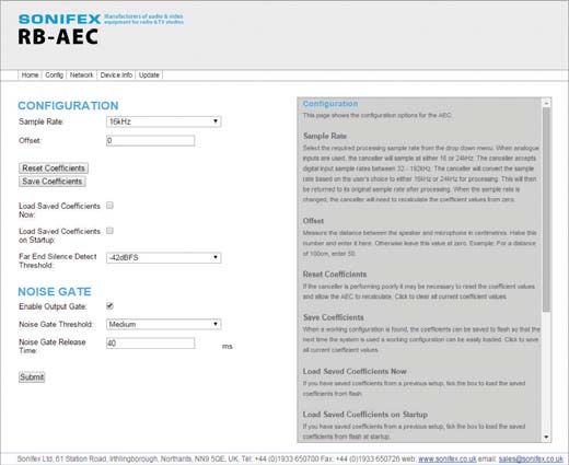
RB-AEC Handbook

This handbook is for use with the following product:
Redbox RB-AEC Acoustic Echo Canceller
Stock Code: 30-285

Revision 1.04, June 2015
©Sonifex Ltd, 2014
All Rights Reserved

Sonifex Ltd, 61, Station Road, Irthlingborough,
Northants, NN9 5QE, England.
Tel: +44 (0)1933 650 700
Fax: +44 (0)1933 650 726
Email: sales@sonifex.co.uk
Website: http://www.sonifex.co.uk

Information in this document is subject to change without notice and does not represent a
commitment on the part of the vendor. Sonifex Ltd shall not be liable for any loss or damage
whatsoever arising from the use of information or any error contained in this manual.

No part of this manual may be reproduced or transmitted in any form or by any means, electronic
or mechanical, including photocopying, recording, information storage and retrieval systems, for any
purpose other than the purchaser’s personal use, without the express written permission of Sonifex
Ltd. Unless otherwise noted, all names of companies, products and persons contained herein are part
of a completely fictitious adaptation and are designed solely to document the use of Sonifex product.
Made in the UK by
Contents & Figures

Contents                                                           The Solution:
                                                                Calibration
                                                                                                                               8
                                                                                                                               9
Product Warranty - 2 Year                                i
   Sonifex Warranty & Liability Terms & Conditions       i    Webserver & Unit Discovery                                      10
                                                                   Running The Webserver                                      10
     1. Definitions                                       i
     2. Warranty                                          i
                                                                Home Page                                                     11
                                                                   Far End and Near End Input Type                            11
   Unpacking Your Product                               iii
                                                                   Adaption Status                                            11
   Repairs & Returns                                    iii
                                                                   Sample Rate                                                12
CE Declaration of Conformity and Approval Information   iv
                                                                   Offset                                                     12
Safety & Installation of Mains Operated Equipment        v
                                                                   Reset Coefficients                                         12
   Voltage Setting Checks                                v
                                                                   Save Coefficients                                          12
   Fuse Rating                                           v
                                                                   Load Saved Coefficients Now                                12
   Power Cable & Connection                              v
                                                                   Load Saved Coefficients on Startup                         12
   WEEE Directive                                       vi
                                                                   Far End Silence Detect Threshold:                          12
   RoHS Directive                                       vi
                                                                   Enable Noise Gate:                                         12
   Atmosphere                                           vi
                                                                   Noise Gate Threshold:                                      13
   Fitting Redboxes                                     vi
                                                                   Noise Gate Release Time:                                   13
Introduction                                             1
     Category                                            1
                                                                Network Page                                                  13
     Product Function                                    1
                                                                Network Settings                                              13
                                                                   Host Name                                                  13
     Typical Applications                                1
                                                                   Static IP Address                                          14
     Features                                            1
                                                                   Static Subnet Mask                                         14
  System Block Diagram                                  2
                                                                   Gateway IP Address                                         14
  Operation of the RB-AEC                               2
                                                                   Dynamic Addressing                                         14
  Front Panel Controls and Indicators                   4
     Power LED                                           4
                                                                Device Info Page                                              14
     Reset Button                                        4
                                                                Update Page                                                   15
                                                                   Update                                                     15
  Rear Panel Connections and Controls                   4
     Inputs                                              4
                                                              Technical Specification For RB-AEC                              16
     Outputs
     Settings DIPSwitch
                                                         4
                                                         5
                                                              Figures
                                                                   Fig 1-1: The RB-AEC Acoustic Echo Canceller                 1
     GPIO Connector                                      6         Fig 1-2: The RB-AEC Operational Block Diagram               2
     Ethernet Port                                       6         Fig 1-3: The RB-AEC Functional Block Diagram                3
     Mains Power                                         6         Fig 2-1: The RB-AEC Front Panel                             4
Applications                                            7          Fig 2-2: The RB-AEC Rear Panel                              5
  How to Remove Delayed Presenter’s Audio From Their               Fig 4-1: The RB-AEC Sonifex Service Discovery Tool         10
  Earpiece                                              7          Fig 4-2: The RB-AEC Webserver Interface - Home             11
     The Problem:                                        7         Fig 4-3: The RB-AEC Webserver Interface - Configuration    12
     The Solution:                                       7         Fig 4-4: The RB-AEC Webserver Interface - Network          13
  How to Remove Delayed Caller Audio From Telephone Line 8         Fig 4-5: The RB-AEC Webserver Interface - Device Info      14
     The Problem:                                        8         Fig 4-6: The RB-AEC Webserver Interface - Update           15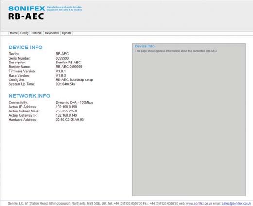
Warranty Registration

Register Online for an
Extended 2 Year Warranty
As standard, Sonifex products are supplied with a 1 year back to base
warranty.
If you register the product online, you can increase your product warranty to
2 years and we can also keep you informed of any product design
improvements or modifications.

To register your product, please go online to www.sonifex.co.uk/register

                         Sonifex Limited y 61 Station Road y Irthlingborough y Northamptonshire y NN9 5QE y United Kingdom
                         Tel: +44 (0)1933 650 700 y Fax: +44 (0)1933 650 726 y Email: technical.support@sonifex.co.uk y Internet: www.sonifex.co.uk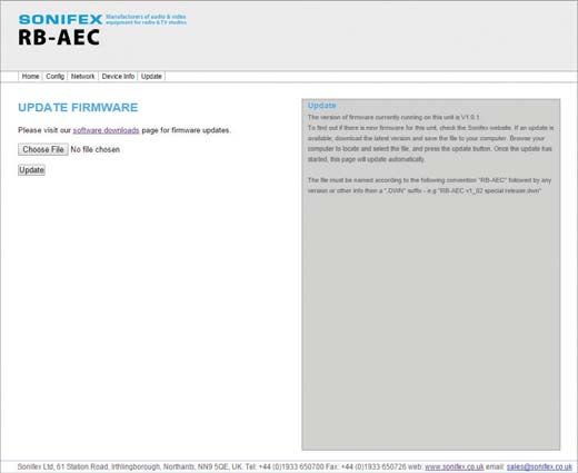
Warranty

Product Warranty - 2 Year                                                      ‘the Contract’ means the quotation, these Conditions of Sale and any
                                                                               other document incorporated in a contract between the Company and the
As standard, Sonifex products are supplied with a 1 year back to base
                                                                               Purchaser.
warranty. In order to register the date of purchase and so that we can keep
you informed of any product design improvements or modifications, it is        This is the entire Contract between the parties relating to the subject
important to complete the warranty registration online. Additionally, if you   matter hereof and may not be changed or terminated except in writing in
register the product on the Sonifex website within 30 days of purchase, you    accordance with the provisions of this Contract. A reference to the consent,
can increase your product warranty to 2 years. Go to the Sonifex website at:   acknowledgement, authority or agreement of the Company means in
http://www.sonifex.co.uk/technical/register/index.asp to apply for your 2      writing and only by a director of the Company.
year warranty.
                                                                               2. Warranty
Note: For your own records the product serial number is recorded on the
                                                                               (a) The Company agrees to repair or (at its discretion) replace Goods
CE certification page of this handbook.
                                                                                    which are found to be defective (fair wear and tear excepted) and
                                                                                    which are returned to the Company within the Warranty Term
Sonifex Warranty & Liability Terms & Conditions                                     provided that each of the following are satisfied:
1. Definitions                                                                       (i)     notification of any defect is given to the Company immediately
‘the Company’ means Sonifex Ltd and where relevant includes companies                        upon its becoming apparent to the Purchaser;
within the same group of companies as Sonifex Limited.
                                                                                     (ii)    the Goods have only been operated under normal operating
‘the Goods’ means the goods or any part thereof supplied by the Company                      conditions and have only been subject to normal use (and
and where relevant includes: work carried out by the Company on items                        in particular the Goods must have been correctly connected
supplied by the Purchaser; services supplied by the Company; and software                    and must not have been subject to high voltage or to ionising
supplied by the Company.                                                                     radiation and must not have been used contrary to the
‘the Purchaser’ means the person or organisation who buys or has agreed                      Company’s technical recommendations);
to buy the Goods.                                                                    (iii)   the Goods are returned to the Company’s premises at the
‘the Price’ means the Price of the Goods and any other charges incurred by                   Purchaser’s expense;
the Company in the supply of the Goods.                                              (iv)    any Goods or parts of Goods replaced shall become the
‘the Warranty Term’ is the length of the product warranty which is usually                   property of the Company;
12 months from the date of despatch; except when the product has been                (v)     no work whatsoever (other than normal and proper
registered at the Sonifex website when the Warranty Term is 24 months                        maintenance) has been carried out to the Goods or any part of
from the date of despatch.                                                                   the Goods without the Company’s prior written consent;

                                                                                                                                                              i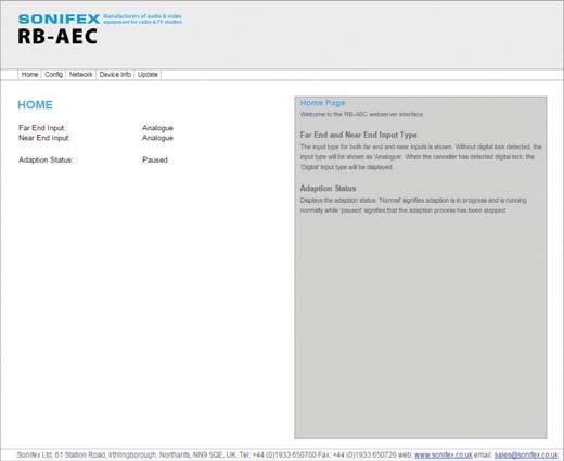
Warranty

       (vi)   the defect has not arisen from a design made, furnished or            (e)   At the request and expense of the Purchaser the Company will test
              specified by the Purchaser;                                                 the Goods to ascertain performance levels and provide a report of
                                                                                          the results of that test. The report will be accurate at the time of the
       (vii) the Goods have been assembled or incorporated into other
                                                                                          test, to the best of the belief and knowledge of the Company, and the
             goods only in accordance with any instructions issued by the
                                                                                          Company accepts no liability in respect of its accuracy beyond that
             Company;
                                                                                          set out in Condition (a).
       (viii) the defect has not arisen from a design modified by the
                                                                                    (f)   Subject to Condition (e) no representation, condition, warranty or
              Purchaser;
                                                                                          other term, express or implied (by statute or otherwise) is given by
       (ix)   the defect has not arisen from an item manufactured by                      the Company that the Goods are of any particular quality or standard
              a person other than the Company. In respect of any item                     or will enable the Purchaser to attain any particular performance
              manufactured by a person other than the Company, the                        or result, or will be suitable for any particular purpose or use
              Purchaser shall only be entitled to the benefit of any warranty or          under specific conditions or will provide any particular capacity,
              guarantee provided by such manufacturer to the Company.                     notwithstanding that the requirement for such performance, result or
                                                                                          capacity or that such particular purpose or conditions may have been
(b)    In respect of computer software supplied by the Company the
                                                                                          known (or ought to have been known) to the Company, its employees
       Company does not warrant that the use of the software will be
                                                                                          or agents.
       uninterrupted or error free.
                                                                                    (g)   (i)    To the extent that the Company is held legally liable to the
(c)    The Company accepts liability:
                                                                                                 Purchaser for any
       (i)    for death or personal injury to the extent that it results from the                single breach of contract, tort, representation or other act or
              negligence of the Company, its employees (whilst in the course                     default, the Company’s liability for the same shall not exceed
              of their employment) or its agents (in the course of the agency);                  the price of the Goods.

       (ii)   for any breach by the Company of any statutory undertaking as               (ii)   The restriction of liability in Condition (g)(i) shall not apply to
              to title, quiet possession and freedom from encumbrance.                           any liability accepted by the Seller in Condition (c).

(d)    Subject to conditions (a) and (c) from the time of despatch of               (h)   Where the Goods are sold under a consumer transaction (as defined
       the Goods from the Company’s premises the Purchaser shall be                       by the Consumer Transactions (Restrictions on Statements) Order
       responsible for any defect in the Goods or loss, damage, nuisance                  1976) the statutory rights of the Purchaser are not affected by these
       or interference whatsoever consequential economic or otherwise or                  Conditions of Sale.
       wastage of material resulting from or caused by or to the Goods. In
       particular the Company shall not be liable for any loss of profits or
       other economic losses. The Company accordingly excludes all liability
       for the same.

ii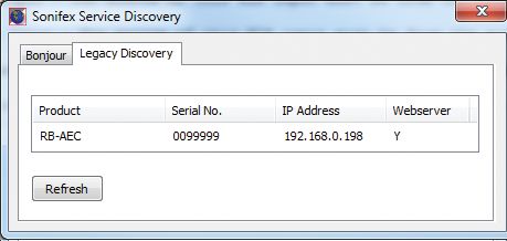
Repairs & Returns

Unpacking Your Product
Each product is shipped in protective packaging and should be inspected
for damage before use. If there is any transit damage take pictures of the
product packaging and notify the carrier immediately with all the relevant
details of the shipment. Packing materials should be kept for inspection and
also for if the product needs to be returned.

The product is shipped with the following equipment so please check to
ensure that you have all of the items below. If anything is missing, please
contact the supplier of your equipment immediately.

 Item                                                    Quantity
 Product Unit                                                1
 IEC Mains lead fitted with moulded mains plug               1
 Handbook and warranty card                                  1

If you require a different power lead, please let us know when ordering the
product.

Repairs & Returns
Please contact Sonifex or your supplier if you have any problems with your
Sonifex product. Email technical.support@sonifex.co.uk for the repair/
upgrade/returns procedure, or for support & questions regarding the
product operation.

പ

                                                                                                   iii
CE Certification
CE Declaration of Conformity and
Approval Information 61 Station Road • Irthlingborough • Northants
NN9 5QE • United Kingdom • www.sonifex.co.uk
T: +44 (0)1933 650 700 • F: +44 (0)1933 650 726
This document certifies that the Sonifex product that you have purchased is
compliant with CE specifications. If you would like further information on
compliance of all Sonifex products, please check the website at the address Product:
above where full information is available.
Sonifex Limited hereby certify that the following product with serial
number shown has been designed and manufactured in accordance with Serial No:
the following specifications :
EMC: EN 55103-1: 1997 Electromagnetic Compatibility. The Reference Technical Justification File for this product is available at
Limits of disturbance for audio apparatus for professional use Sonifex Ltd.
For use in environments 1 to 4.
EN 55103-2: 1997 Electromagnetic Compatibility. Authorised By:
Limits of disturbance for audio apparatus for professional use
Name: Chris Stills
For use in environments 1 to 4.
Position: Technical Director
Safety: EN 60950: 1992 Safety of Information Technology Equipment
Including Electrical Business Equipment. Date of Issue: 01 November 2014
Hybrid BS6301, BS7002, BS415, CTR21,
Approvals: R&TTE directive (1999/5/EC) Signature:
R e g i s t e r e d O f f i c e • 6 1 S t a t i o n R o a d • I r t h l i n g b o r o u g h • R e g i s t e r e d i n E n g l a n d 1 7 1 7 8 6 4 • VAT R e g N o . G B 1 1 9 8 5 3 2 5 2
ivSafety & Installation
Safety & Installation of Mains Power Cable & Connection
Operated Equipment An IEC power connector is supplied with the product which has a moulded
plug attached – this is a legal requirement The mains lead is automatically
There are no user serviceable parts inside the equipment. If you should
configured for the country that the product is being sent to, from one of :
ever need to look inside the unit, always disconnect the mains supply
before removing the equipment covers. The cover is connected to earth Territory Voltage IEC Lead Type Image
by means of the fixing screws. It is essential to maintain this earth/
ground connection to ensure a safe operating environment and provide UK & Middle East 230V UK 3 pin to IEC lead
electromagnetic shielding.
European Schuko round 2 pin to
Europe 230V
IEC lead
Voltage Setting Checks
Ensure that the machine operating voltage is correct for your mains power USA, Canada and
115V 3 flat pin to IEC lead
supply by checking the box in which your product was supplied. The voltage South America
is shown on the box label. The available voltage settings are 115V, or 230V. Australia & New
Please note that all products are either switchable between 115V and 230V, 230V Australasian 3 flat pin to IEC lead
Zealand
or have a universal power supply.
Connect the equipment in accordance with the connection details and
before applying power to the unit, check that the machine has the correct
Fuse Rating operating voltage for your mains power supply.
The product is supplied with a single fuse in the live conducting path of the
mains power input. For reasons of safety it is important that the correct Important Note: If there is an earth/ground terminal on the rear panel of
rating and type of fuse is used. Incorrectly rated fuses could present a the product then it must be earthed/grounded.
possible fire hazard, under equipment fault conditions. The active fuse is
fitted on the outside rear panel of the unit.
vSafety & Installation
WEEE Directive processes include the assembly of purchased components from various
The Waste Electrical and Electronic Equipment (WEEE) sources. Product is offered as RoHS compliant, or LF, only after sufficient
Directive was agreed on 13 February 2003, along with the evidence is received from the component manufacturers that their
related Directive 2002/95/EC on Restrictions of the use of components are RoHS compliant. Sonifex Ltd relies solely on the distributor,
certain Hazardous Substances in electrical and electronic or manufacturer, of the components for identification of RoHS compliance.
equipment (RoHS). The Waste Electrical and Electronic Equipment Directive Thus whilst every effort is made to ensure compliance, Sonifex Ltd makes
(WEEE) aims to minimise the impacts of electrical and electronic equipment no warranty, or certification, or declaration of compliance concerning said
on the environment during their life times and when they become waste. components.
All products manufactured by Sonifex Ltd have the WEEE directive label
placed on the case. Sonifex Ltd will be happy to give you information about Atmosphere
local organisations that can reprocess the product when it reaches its “end The units should be installed in an area that is not subject to excessive
of use”, or alternatively all products that have reached “end of use” can be temperature variation (50°C), moisture, dust or vibration.
returned to Sonifex and will be reprocessed correctly free of charge.
Fitting Redboxes
RoHS Directive Redboxes can be fixed to the underside of a mixing desk, or other surfaces
The RoHS directive limits the use of certain hazardous using 4.2mm holes in the sides and fixed with 2 x M4 screws or 2 x No. 6
substances currently used in EEE manufacture, including countersink wood screws.
lead, mercury, cadmium, hexavalent chromium, and
halide-containing compounds PBB (polybrominated biphenyl) and PBDE They can also be rack-mounted, with either the front, or rear of the Redbox
(polybrominated diphenyl ether). Elimination of these substances will result positioned at the front of the rack:
in more environmentally friendly recycling of electronic equipment. Rear Mounting a 1U Rackmount Redbox:
Sonifex Ltd practices lead-free (LF) manufacturing processes and does not The RB-RK3 1U rear panel rack kit can be used for large 1U rackmount
use any of the hazardous substances identified in the European Union’s Redboxes.
Restriction of Hazardous Substances (RoHS) directive. The manufacturing
Note: When fitting the RB-RK3 rear-mounting rack-kits, a notch has been left on the inside of the right-hand rack-piece for the mains cable to pass through.
Make sure that the mains cable has been put through the notch before attaching the right hand rack-piece.
viIntroduction 1
Introduction
Fig 1-1: The RB-AEC Acoustic Echo Canceller
Category in which the control room microphones are placed. Although acoustic echo
Synchronisers, Delays & Silence Detectors. cancellation is more commonly implemented in telephony systems, the
Sonifex RB-AEC is designed to produce broadcast quality cancellation.
Product Function
Remove acoustic echo in a presenter’s earpiece caused by microphones Much like during a conference call configuration between two rooms, each
picking up audio from loudspeakers in delay. room has a microphone and speaker to conduct a conversation. When an
occupant of one room speaks, it takes a certain length of time before it
Typical Applications is received in the second room. Without a suitable solution this ‘delayed’
In a TV production environment where presenters are fed a signal which has signal can then be captured by the microphone in the second room and
some form of acoustic delay or echo. Any situation where adaptive echo returned back to the first room as an echo.
cancellaton is required.
In the particular example of TV production, as well as the processing/
Features transmission delay, sound reflections from the control room monitor
The RB-AEC 1U rack-mount is an acoustic echo canceller primarily designed speaker into the control room microphone(s) cause the studio earpiece to
for the benefit of studio personnel for television and radio. When a studio suffer further delay. The sound reflections in the control room vary with
presenter’s microphone signal is played out through a monitor speaker in the contents of the room including any personnel present. Also, different
the control room, it can be picked up by the control room microphone(s) frequencies produce varying reflections across various types of surfaces
and returned to the presenter’s earpiece as an undesirable echo. and magnitudes within the room. For a 15m distance between speaker and
microphone the delay is as much as 40ms.The DSP solution offered by the
In circumstances where green screen video processing is taking place, the RB-AEC can dynamically compensate for varying configurations.
delay can be greater than 200ms. Additionally, the dimensions, occupancy
and distance between mouth and microphone can further influence the
echo. The RB-AEC is used to remove the entire control room monitor
speaker output from the presenter’s feed by adapting to the environment
11 Introduction
Operation of the RB-AEC The RB-AEC is a high performance, reliable single channel acoustic echo
The post-processed transmission output program from the studio (A) is canceller designed to be a transparent addition to an exisiting studio
sent to the RB-AEC as an analogue or digital audio signal (the stereo input environment.
is auto-sensing) which acts as a mix-minus to the input signal (B) from
The canceller will auto-detect analogue and digital inputs with sample rates
the Control Room. The RB-AEC removes the unwanted acoustic echoes so
up to 192kHz. Digital output is available when using a digital input and its
that the audio sent to the presenter’s earpiece (C) is free of echoes and
sample rate is set to the rate detected at the input.
reflection artifacts.
The settings for the RB-AEC are adjusted using the onboard webserver
interface.
System Block Diagram
Before After
Studio Studio
Monitor/ Monitor/
Earpiece Mic Earpiece Mic
Presenter Receiving
Artifact Free Audio (C)
Presenter Approx 200ms Approx 200ms
Receiving Delay RB-AEC Delay
Delayed T(z)
Audio Vol (A) Vol
(B)
Monitor Monitor
TB TB
Mic Mic
Control Room/ Speaker Control Room/ Speaker
Gallery Gallery Fig 1-2: The RB-AEC
Output Output
Operational Block Diagram
2Introduction 1
ANA/AES Input ANA Output
ADC DSP DAC ANA Output
ANA/AES Input AES Output
SRC SRC
SRC
Fig 1-3: The RB-AEC Functional Block Diagram
32 Connections and Operation
Front Panel Controls and Indicators
Power Reset
LED Button
Fig 2-1: The RB-AEC Front Panel
Power LED The source of this XLR input must be from the audio feed that is the source of
The POWER LED illuminates whilst internal power is present within the echo. This is used by the cancelling algorithm to calculate what to remove
the unit. If this indicator is not on, the most likely reason is simply the from the near end.
absence of mains power, but under fault conditions it may also indicate
Near End Input
a ruptured mains fuse or a problem with the internal power supply
An XLR 3 pin socket is used for the NEAR END input channel and it can take
module.
an analogue or AES/EBU digital feed. The input will automatically detect
Reset Button whether the source is analogue or digital. It is electronically balanced, with
In the unlikely event that the unit fails to respond, press and hold the the following connections:
reset button for 3 seconds to reboot the unit Pin 1: Screen.
Pin 2: Phase.
Rear Panel Connections and Controls Pin 3: Non-phase.
Inputs The source of this XLR input must be from the audio feed that is
Far End Input contaminated with the echo. It is from this feed, that the cancelling algorithm
An XLR 3 pin socket is used for the FAR END input channel and it can will be subtracting it’s echo estimation to produce an echo free result.
take an analogue or AES/EBU digital feed. The input will automatically
detect whether the source is analogue or digital. It is electronically Outputs
balanced, with the following connections: Analogue Outputs 1 & 2
The analogue outputs consist of two XLR male connectors professionally
Pin 1: Screen.
balanced with following connections:
Pin 2: Phase.
Pin 3: Non-phase. Pin 1: Screen.
Pin 2: Phase.
Pin 3: Non-phase.
4Connections and Operation 2
Analogue & Analogue Digital GPIO
Digital Inputs Outputs Output Settings Connector Ethernet Port Fuse Mains Input
Fig 2-2: The RB-AEC Rear Panel
Both channels contain the same signal. When using analogue as the input Settings DIPSwitch
type, only analogue outputs are enabled. Unit Settings are configured using a 4 way DIPSwitch:
Digital Output Settings DIPSwitch
The digital output is connected using a male XLR connector on the rear 1 Far end digital input termination. ON = Terminated, OFF =
ƉĂŶĞů͘dŚŝƐy>ZϯƉŝŶƉůƵŐŚĂƐĂŶŝŵƉĞĚĂŶĐĞŽĨϭϭϬɏǁŝƚŚƚŚĞĨŽůůŽǁŝŶŐ Unterminated
connections: 2 Near end digital input termination. ON = Terminated, OFF =
Unterminated
Pin 1: Screen.
3 ON = Bootstrap mode, OFF = Normal mode
Pin 2: Phase.
4 ON = Disable cancellation (Bypass), OFF = Enable cancellation
Pin 3: Non-phase.
When using analogue as the input type, this output is disabled. Input Termination
ϭϭϬɏŝŶƉƵƚƚĞƌŵŝŶĂƚŝŽŶĨŽƌƚŚĞ
^ͬ
hĚŝŐŝƚĂůŝŶƉƵƚƐĂƌĞĐŽŶƚƌŽůůĞĚďLJƚŚĞ
General Note About Inputs & Outputs settings of DIPSwitches 1 and 2, as follows:
The analogue and digital outputs will both be present when digital inputs
are used. The digital output is disabled when an analogue input is used SW1:tŚĞŶƐĞƚƚŽKE͕&ĂƌĞŶĚĚŝŐŝƚĂůŝŶƉƵƚŝƐƚĞƌŵŝŶĂƚĞĚǁŝƚŚϭϭϬɏ͘
because it detects the clock from the digital input to detect the input/ SW2: tŚĞŶƐĞƚƚŽKE͕EĞĂƌĞŶĚĚŝŐŝƚĂůŝŶƉƵƚŝƐƚĞƌŵŝŶĂƚĞĚǁŝƚŚϭϭϬɏ͘
output sample rate. However, it it is possible to use different analogue and
Bootstrap Mode
digital input configurations for the Near End and Far End inputs.
To enable bootstrap mode, power the unit off, switch DIPSwitch 3 to ON
and power up the unit. The RB-AEC can now be programmed with new
firmware.
Warning: This removes the main firmware from the unit and should not
be necessary unless the unit has been loaded with incorrect or corrupt
52 Connections and Operation
firmware. Once in Bootstrap Mode you will need to load main firmware Ethernet Port
into the device using a standalone application. Contact Sonifex for more The Ethernet port is connected using a standard RJ-45 connector on the
information. rear of the panel. It is a 10/100Mbps link. The unit can be controlled
remotely over the Ethernet connection using the built-in webserver. By
Bypass Cancellation default the unit is configured for dynamic addressing using DHCP and Auto-
To test whether the product is effective in your application, you can IP. If a static IP address is required then this must be configured through the
configure it and then toggle DIPSwitch 4 to listen to the effect with (OFF) webserver.
and bypassed without (ON) cancellation.
The connections for the RJ45 connector are as follows:
GPIO Connector
This a 9 way D-type socket with the following connection details: Ethernet Connector (RJ-45)
Pin No. Function
GPIO Pin Pin 1 Transmit data (+)
Pin No Signal I/O Description Pin 2 Transmit data (-)
Pin 1 GPO1 O General purpose output 1 - Power good Pin 3 Receive data (+)
Pin 4 No connection
Pin 2 GPO2 O General purpose output 2
Pin 5 No connection
Pin 3 GPO3 O General purpose output 3
Pin 6 Receive data (-)
Pin 4 GPI1 I General purpose input 1 - Mute input detect Pin 7 No connection
Pin 5 GPI2 I General purpose input 2 Pin 8 No connection
Pin 6 GPI3 I General purpose input 3
Mains Power
Pin 7 12VDC - 50mA fused +12V power supply Power is applied via a standard three-pin IEC male socket. Mains voltages
Pin 8 DGND - Ground return for external circuits between 85V and 264V AC and frequencies between 47 and 63Hz are
accepted without adjustment.
Pin 9 DGND - Ground return for external circuits
A 2A, 5 x 20mm SB fuse is used. The Earth pin MUST be connected to
Power Good ensure safety.
Pin 1 shows a power fail condition. This open collector output is normally
HIGH. Should a power failure occur, this level will go low (DGND).
Mute Input Detect
Setting the mute input detect pin 4 to DGND 0V will disable adaption.
This may prevent the canceller from becoming unstable when the input is
muted.
6Applications 3
Applications The Solution:
1. Connect the director’s microphone signal (at line level) to the RB-AEC
How to Remove Delayed Presenter’s Audio From near-end input.
Their Earpiece 2. Connect the gallery monitor signal (at line level, containing the
presenter’s microphone audio) to the RB-AEC far-end input.
The Problem:
3. Connect the RB-AEC output(s) to the presenter’s earpiece(s). Turn on the
Microphone audio from the presenter(s) is played aloud in the control
RB-AEC.
room/gallery, where a live microphone allows the director to talk to the
4. Allow the presenter(s) to talk for 1 minute without the director using
presenter(s) via their earpiece(s). This live microphone also inadvertently
their microphone (though it must still be active). The RB-AEC will
picks up the presenter’s microphone audio and feeds it back to them in
learn the environment and the echo will gradually disappear from the
delay, causing a disconcerting self-echo in their earpiece.
presenter’s earpiece(s). The coefficients are stored and loaded on power-
up. This process will not need repeating unless the environment changes.
Amp To Presenter’s
Earpiece
Studio
Control Room/
Gallery
M
Line Level
Amp
Line Level
73 Applications
How to Remove Delayed Caller Audio From The The Solution:
Telephone Line 1. Connect the mixed studio microphones signal (at line level) to the RB-
AEC near-end input.
The Problem:
2. Connect the TBU output to the RB-AEC far-end input.
Caller audio from the telephone hybrid is played aloud in the TV studio,
3. Connect the RB-AEC output(s) to the hybrid’s input (in line mode). Turn
where live microphones are fitted to presenters and guests (boundary
on the RB-AEC.
microphones may also be present). These live microphones also
4. Make a test call and allow the caller to talk for 1 minute, their voice
inadvertently pick up the caller’s audio and feed it back to them in delay,
played aloud through the studio monitor and being picked up by all
causing an undesirable self-echo.
studio microphones (which should be in-position and active but not
being used). The RB-AEC will learn the environment and the echo will
gradually disappear from the phone line. The coefficients are stored and
loaded on power-up. This process will not need repeating unless the
environment changes.
TV Studio
Studio Mics
(Presenter/Guest/Boundary) Amp
Amp
Telephone Line
Sound Studio
Line Level Line Level
8Applications 3
Calibration
When using the RB-AEC for the first time, the unit must first be calibrated
to suit the environment in which it will be used. Using the webserver, select
the ‘Config’ tab.
1. Select the desired sample rate.
2. Measure the distance between the speaker and microphone in
centimetres. Halve this number and enter it here. Example: For a
distance of 100cm, enter 50. Otherwise leave this value at zero.
3. Tick the box labelled ‘Load Saved Coefficients on Startup’. This will ensure
that any saved coefficients are used next time the unit is switched on.
4. Set the presenter’s(Far End) silence detect threshold. Levels below this
value will disable the canceller.
5. You also have the option of enabling the noise gate, setting the threshold
and changing the release time.
6. Submit your settings
7. For calibration, ensure the control room is silent and speak into the
presenter’s microphone while monitoring using the presenter’s earpiece
for around one minute or until the echo has subsided to a satisfactory
level.
8. Save your coefficient values so they can be used as a starting point for
next time the RB-AEC is used.
94 Network Discovery and Webserver
Webserver & Unit Discovery
The RB-AEC uses the Zeroconf networking methodology to allow the unit to The Sonifex device can be detected using the Sonifex Discovery Tool and the
be a “plug and play” device. Just simply connect it to the network and use device’s webserver may be launched.
it. The unit is assigned an IP address using a DHCP server, or a self-assigned
Bonjour is available as standard on MAC OS and as plug-in for Internet
address using AUTOIP when one isn’t available. The RB-AEC can also use
Explorer for the ‘Bonjour for Windows’ download. You can also use the
Bonjour discovery on a network.
discovery application provided by Sonifex and available for download on the
Once the RB-AEC has been connected to the network, it will try to obtain Sonifex website www.sonifex.co.uk
an IP address from a DHCP server on the network. If none is found then the
unit will use Auto-IP to assign itself an IP address. Running The Webserver
Use Google Chrome or Mozilla Firefox browsers and simply type in the
There is no direct method for you to determine exactly which IP address has RB-AEC IP address.
been assigned to the unit. However, using a Bonjour discovery application
or browser plug-in, the unit can be discovered and connected to with
relative ease.
Fig 4-1: The RB-AEC Sonifex Service Discovery Tool
10Network Discovery and Webserver 4
Home Page Welcome to the RB-AEC1 webserver interface.
The input type for both far end and near inputs is shown. Without an AES/
The input type for both far end and near inputs is shown. Without digital
EBU digital lock detected, the input type will be shown as ‘Analogue’. When
lock detected, the input type will be shown as ‘Analogue’. When the
the unit has detected digital lock, the ‘Digital’ input type will be displayed.
canceller has detected digital lock, the ‘Digital’ input type will be displayed.
Far End and Near End Input Type
The input type for both far end and near inputs is shown. Without digital
lock detected, the input type will be shown as ‘Analogue’. When the
canceller has detected digital lock, the ‘Digital’ input type will be displayed.
Adaption Status
Displays the adaption status. ‘Normal’ signifies adaption is in progress and
is running normally while ‘paused’ signifies that the adaption process has
been stopped.
Fig 4-2: The RB-AEC Webserver Interface - Home
114 Network Discovery and Webserver
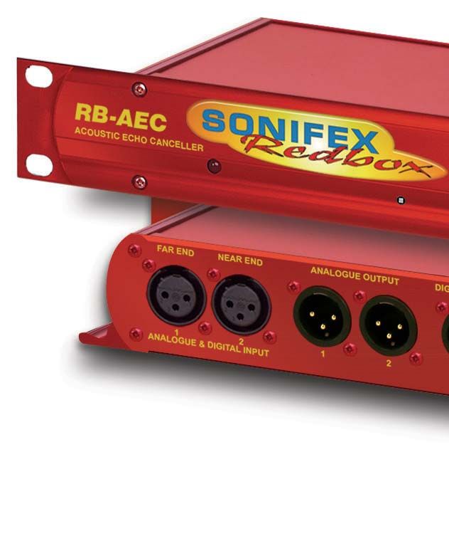
Configuration Page Offset
Measure the distance between the speaker and microphone in centimetres.
This page shows the configuration options for the RB-AEC.
Halve this number and enter it here. Otherwise leave this value at zero.
Example: For a distance of 100cm, enter 50.
Reset Coefficients
If the canceller is performing poorly it may be necessary to reset the
coefficient values and allow the AEC to recalculate. Click to clear all current
coefficient values.
Save Coefficients
When a working configuration is found, the coefficients can be saved to
flash so that the next time the system is used a working configuration can
be easily loaded. Click to save all current coefficient values.
Load Saved Coefficients Now
If you have saved coefficients from a previous setup, tick the box to load the
saved coefficients from flash.
Load Saved Coefficients on Startup
If you have saved coefficients from a previous setup, tick the box to load the
saved coefficients from flash at startup.
Far End Silence Detect Threshold:
Fig 4-3: The RB-AEC Webserver Interface - Configuration This value sets the threshold at which the adaption process is paused
during periods where no-one is speaking at the far end. Select a threshold
Sample Rate
from the drop down list. -6dBFS will set the threshold to half of the
Select the required processing sample rate from the drop down menu.
maximum value, while ‘No Threshold’ will allow the adaption to continue
When analogue inputs are used, the canceller will sample at either 16
all the time.
or 24kHz. The canceller accepts digital input sample rates between 32 -
192kHz. The canceller will convert the sample rate based on the user’s Enable Noise Gate:
choice to either 16kHz or 24kHz for processing. This will then be returned to When enabled, the noise gate will lower the output level based on the
its original sample rate after processing. When the sample rate is changed, threshold set below.
the canceller will need to recalculate the coefficient values from zero.
12Network Discovery and Webserver 4
Noise Gate Threshold: Network Page
This threshold sets the point at which the noise gate is enabled or disabled. Displays the Hostname, Static IP Address, Static subnet mask, Gateway IP
address, and whether DHCP and Auto IP are enabled.
Noise Gate Release Time:
After the noise gate has been triggered, a length of time can be set before
the gate can be released. This helps prevent the gate from being activated
during speech. Set a time in milliseconds between 0 and 500.
Fig 4-4: The RB-AEC Webserver Interface - Network
Network Settings
Host Name
Enter the host name used by Bonjour. The Host name can be up to 63
alphanumeric characters in length, and can include hyphens (-). If a conflict
occurs on the network this value may be overwritten.
134 Network Discovery and Webserver
Static IP Address Device Info Page
Enter the static IP address that you wish to assign to this unit. This IP This page shows general information about the connected RB-AEC.
address will be used if Dynamic addressing is disabled.
The default static IP address is 192.168.0.100
Static Subnet Mask
Enter the subnet mask of the network you wish to connect to.
The default subnet mask is 255.255.255.0
Gateway IP Address
Enter the gateway IP address of your router.
The default gateway is 192.168.0.1
Dynamic Addressing
Enable dynamic addressing to allow the unit to acquire it’s IP address
automatically from a DHCP server or using AUTOIP. Disable dynamic
addressing to use the static IP address entered on this page.
To transfer the new network settings to the connected RB-AEC, press the
Submit button. This may require a restart by Internet Explorer
Fig 4-5: The RB-AEC Webserver Interface - Device Info
14Network Discovery and Webserver 4
Update Page automatically.
To update the RB-AEC firmware, download the latest file from the Sonifex
The file must be named according to the following convention “RB-AEC”
website, select Choose File to find it and click Update to load it into the
followed by any version or other info then a “.DWN” suffix - e.g “RB-AEC
RB-AEC.
v1_02 special release.dwn”
Fig 4-6: The RB-AEC Webserver Interface - Update
Update
The version of firmware currently running on this unit is V1.0.6.
To find out if there is new firmware for this unit, check the Sonifex website.
If an update is available, download the latest version and save the file to
your computer. Browse your computer to locate and select the file, and
press the update button. Once the update has started, this page will update
155 Technical Specification
Technical Specification For RB-AEC
Audio Specification Remote I/O Port: 9 way D-type socket
Audio Input 1 x mono analogue or AES/EBU digital on XLR Ethernet Port: 1 x RJ45 with status LEDs
(Near End/Program): 3-pin female (autoselecting) Mains Input: Filtered IEC, continuously rated 85
Audio Input 1 x mono analogue or AES/EBU digital on 264VAC @ 47-63Hz, 10W max
(Far End/ From XLR 3-pin female (autoselecting) Fuse Rating: Anti-surge fuse 1A 20 x 5mm
Control Room):
Max Level +18dBu (analogue)
(0dB Input Gain): 0dBFS (digital) Controls
CMRR: >60dB typical Configuration: 1 x Ethernet port, webserver
1 x rear panel 4-way DIPSwitch
/ŶƉƵƚ/ŵƉĞĚĂŶĐĞ͗ ϮϬŬɏ;ĂŶĂůŽŐƵĞͿϭϭϬɏ;ĚŝŐŝƚĂůǁŝƚŚƚĞƌŵŝŶĂƚŝŽŶ
switchable) Reset: 1 x front panel recessed button
AES/EBU Input: 32kHz to 192kHz
Equipment Type
Audio Outputs 2 x mono analogue on XLR 3-pin male
RB-AEC: Acoustic echo canceller
(Analogue):
Audio Outputs 1 x stereo digital AES/EBU on XLR 3-pin male
(AES/EBU): Physical Specification
Maximum Output +18dBu (analogue)/ Dimensions (Raw): 48cm (W) x 10.8cm (D) x 4.2cm (H)(1U)
Level: 0dBFS (digital) 19” (W) x 4.3” (D) x 1.7” (H) (1U)
KƵƚƉƵƚ/ŵƉĞĚĂŶĐĞ͗ фϱϬɏ;ĂŶĂůŽŐƵĞͿͬϭϭϬɏ;ĚŝŐŝƚĂůͿ Dimensions (Boxed): 58.5cm (W) x 22.5cm (D) x 7cm (H)
23” (W) x 8.9” (D) x 2.8” (H)
AES/EBU Output Selectable 32kHz - 192kHz
Sample Rates: Weight: Nett: 1.5kg Gross: 2.0kg
Nett: 3.3lbs Gross: 4.4lbs
Distortion: fs = 16kHz, THD+NNotes
www.sonifex.co.uk
t:+44 (0)1933 650 700
f:+44 (0)1933 650 726
sales@sonifex.co.uk
You can also read