Requirements for speed distribution in the measured section of a flume for training and diagnosis in competitive swimming
←
→
Page content transcription
If your browser does not render page correctly, please read the page content below
TZ Technisches Zentrum Entwicklungs- & Handelsgesellschaft mbH

Dr.-Ing. habil. Klaus Döge

 Requirements for speed distribution in the measured section of a flume
         for training and diagnosis in competitive swimming

Introduction
Publications frequently claim that a flume is well suited for top-class sport and other uses
without the authors dealing with the question of speed distribution in the measured section of
water. The parameters necessary for checking suitability are very often not listed The
intention below is to demonstrate how important the demands placed on speed distribution in
the measured section are.
Speed distribution should be understood to be the magnitude and direction of speed and
strictly speaking its fluctuation over the entire measured section. In this regard, the cross-
section in the measured section is certainly greater than the athletes' area of action in the
various swimming strokes.
The demands placed on speed distribution are also determined by the fact that the
movement sequences optimised during training in the flume should also be the optimum for
swimming in a pool and that the results of the diagnosis should not depend on the channel
used. Only optimum movement sequences in competition ensure success in sport.
The point of departure for the design of a swimming channel is therefore the requirement of a
deviation in speed from the average and the size of the control cross-section still to be
defined. These are the decisive parameters for the structural form and operating costs of the
flume. When planning a flume, a decision has to be made based on an economic analysis
and other factors as to whether the required quality of speed distribution in the control
section should be achieved more through construction effort such as the selection of a
greater flow cross-section for water circulation or through fittings that result in speed loss and
higher energy costs. In any event, costs increase dramatically with the demands placed on
speed distribution and the size of the control section.
Besides the requirements relating to speed distribution, additional requirements must be met
relating to rippling on the surface of the water, air-bubble content and thus water
transparency and water hygiene. These are outside the scope of this document.

Fault analysis
The criterion for all flumes is the swimming conditions in the pool. Athletes move in calm
water, i.e. the speed is zero everywhere. Their body surfaces are subjected to location- and
time-dependent normal and tangential force, weight and inertial force. All these forces are
determined by the time-dependent geometry of the athletes and their sequence of
movements and linked with each other via momentary equilibrium conditions.
In order for exactly the same forces to apply in the flume under the same conditions, i.e. the
same geometry and sequence of movements, the water across the whole control section
must flow at exactly the average speed of swimming. In this case the flow of water around
the athletes in the pool and in the flume will be exactly the same. If the speed distribution is
not constant in the measured section, different normal and tangential forces will lead to

                                                                                                 1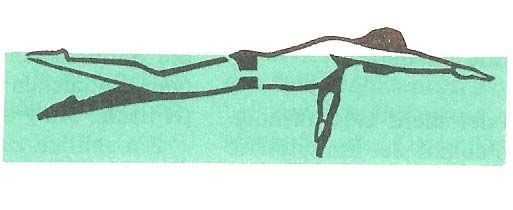
TZ Technisches Zentrum Entwicklungs- & Handelsgesellschaft mbH
different momentary force equilibrium states and ultimately to different inertial forces, floating
positions and movement sequences. The effects of deviation from a constant speed
distribution are so complex that an estimate of these effects is made for special cases below.
A crawl swimmer was selected because in this case forward propulsion is determined to a
particular degree through arm movement.
ux
FA x
w x cx
Fig. 1 speeds and propelling force at the palm of a crawl swimmer
The propelling force is mainly effected at the palm through the oncoming flow and its relative
speed in the movement of direction (x direction) w x .
2
FA x c W A wx
2
( c W drag coefficient of palm, A facing surface of palm, density of the water)
The relative speed w x results from the speed of the palm in absolute system u x and the
water speed c x according to the kinematic basic equation for direction x.
w x ux c x
Two borderline cases may be considered for the incorrect effects of a speed of water moving
downwards to the floor at the palm:
1. The swimmer does not react to the change in the driving force with a change in the
speed of the palm. This results in two faults in the relative speed and consequently in
the momentary propelling force.
w x c x
wx wx
2
TZ Technisches Zentrum Entwicklungs- & Handelsgesellschaft mbH
FA x w x c x
2 2
FA x wx wx
2. The swimmer maintains his propelling force. This results in a change in the relative
speed but not in the speed of the palm.
ux w x c x
100
Fehler der momentanen Antriebskraft in %
80
60
40
20
fehlerfrei: ux=4,00m/s, cx=1,85m/s
Bedingung: ux/ux=0
0
0 20 40 60 80 100
Fehler der Wassergeschwindigkeit am Handteller in %
Fig. 2 Fault in driving force with incorrect water speed and
unchanged absolute movement of the palm (borderline case 1)
3TZ Technisches Zentrum Entwicklungs- & Handelsgesellschaft mbH
50
Fehler der Geschwindigkeit des Handtellers in %
40
30
20
10
fehlerfrei: ux=4,00m/s, cx=1,85m/s
Bedingung: FA x/FA x=0
0
0 20 40 60 80 100
Fehler der Wassergeschwindigkeit am Handteller in %
Fig. 3 Fault in absolute speed of the palm with incorrect
water speed and unchanged driving force (borderline case 2)
The fault in the absolute speed of the palm with incorrect water speed and unchanged driving
force results in:
u x u x c x
ux ux
Apart from the effects on propulsion, there are further significant effects that result from
incorrect water speed. For example, the swimmer's angle of inclination and resistance
increase when water speed is directed downwards to the floor.
Summing up it can be stated that major faults in water speed can have significant effects on
driving force and sequence of movement. The same conclusions result for other swimming
strokes.
Size of control and inflow cross-section
In fluid metrology, and thus in the present case, the size of the control section is of
fundamental significance for reasons of measuring accuracy and operating costs. For this
reason, comprehensive investigations into the influence of the control section were
performed for wind tunnels. Results showed that the normal surface of the measured object
facing the flow has to be much smaller than the jet cross-section corresponding to the inlet
area into the measured section. Since there are no known analogous investigations into the
influence on swimmers in flumes, it is recommended to select a minimum water depth of 1.0
m and a minimum lane width of 2.5 m in accordance with the technical rules of FINA. 25 cm
is a sensible addition to the water depth to accommodate a racing dive. With regard to the
lane width, it is worth considering an addition of 2 x 20 cm to take account of the fact that
there are two pool edges.
4TZ Technisches Zentrum Entwicklungs- & Handelsgesellschaft mbH
These dimensions meet the requirements of FINA for a competitive pool as boundary
conditions and for the size of the flume.
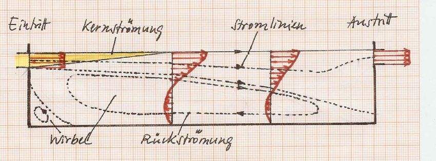
Water circulation channels are occasionally designed in such a way that an inlet flow takes
place in only one part of the control section, e.g. just below the water surface. This results in
the formation of a "free jet" current. This is characterised by a very large eddy in the
unaffected control section with a back flow, rapidly decreasing speeds in the direction of the
floor and to the pool outlet, flow lines falling in the direction of the floor around the swimmer
and significant turbulence, see figure 4. The area around the core stream flow is also marked
in the diagram. The inlet speed assumed to be constant only exists in this core stream flow.
Fig. 4 Longitudinal section view of a flume with inlet current
only in the upper section of the control section (free current)
Eintritt – inlet
Wirbel – eddy
Kernströmung – core current
Stromlinien – flow lines
Rückströmung – back flow
Austritt – outlet
The free jet current in the upper part of the pool results in major faults in the water speed and
current direction with the effects described above for drive and resistance conditions for the
athletes.
If the inlet current cross-section does not cover the entire width of the pool a free jet current
will occur across the pool width with the effects described above.
Conclusions
If the inlet flow extends over the entire control section, and after allowing for friction at the
walls and for swirl-free inlet current, fluctuations in water speed will only be caused by inlet
flow speed. By carefully designing the fluid characteristics, these can be kept within the
range of a few percent. Speed does not change in the direction of the current; the flow lines
are exactly parallel.
If the control section is designed in accordance with the rules described above and if the inlet
current is constant, it is possible to model the conditions in a swimming pool completely. In
the event of slight changes in the inlet flow speed, it is possible to estimate the effects on the
propelling force and arm speed using the diagrams supplied. They are also slight.
If the inlet current only extends over the upper part of the measured section and if the
swimmer's arm movement goes beyond the core area of the resulting free jet current, major
faults will occur in propelling force, arm speed and resistance as a result of non-parallel
currents. In these circumstances the flume is not suitable for diagnosis and serious
technique training.
5You can also read